EP0904712A2 - Cosmetic pot with internal hinged tray - Google Patents
Cosmetic pot with internal hinged tray Download PDFInfo
- Publication number
- EP0904712A2 EP0904712A2 EP98202978A EP98202978A EP0904712A2 EP 0904712 A2 EP0904712 A2 EP 0904712A2 EP 98202978 A EP98202978 A EP 98202978A EP 98202978 A EP98202978 A EP 98202978A EP 0904712 A2 EP0904712 A2 EP 0904712A2
- Authority
- EP
- European Patent Office
- Prior art keywords
- display
- jar
- type applicator
- set forth
- neck portion
- Prior art date
- Legal status (The legal status is an assumption and is not a legal conclusion. Google has not performed a legal analysis and makes no representation as to the accuracy of the status listed.)
- Withdrawn
Links
- 239000002537 cosmetic Substances 0.000 title claims abstract description 18
- 238000007789 sealing Methods 0.000 claims abstract description 32
- 229920003023 plastic Polymers 0.000 claims abstract description 12
- 239000000463 material Substances 0.000 claims abstract description 10
- 239000004033 plastic Substances 0.000 claims abstract description 10
- 230000002093 peripheral effect Effects 0.000 claims description 13
- 229920001903 high density polyethylene Polymers 0.000 claims description 4
- 229920000098 polyolefin Polymers 0.000 claims description 4
- 230000004888 barrier function Effects 0.000 claims 1
- 238000013461 design Methods 0.000 description 5
- 239000011324 bead Substances 0.000 description 4
- 239000002131 composite material Substances 0.000 description 3
- 239000000126 substance Substances 0.000 description 3
- 238000010276 construction Methods 0.000 description 2
- 230000008021 deposition Effects 0.000 description 2
- 229920001971 elastomer Polymers 0.000 description 2
- 239000000203 mixture Substances 0.000 description 2
- 238000012856 packing Methods 0.000 description 2
- 241001237961 Amanita rubescens Species 0.000 description 1
- 241001272720 Medialuna californiensis Species 0.000 description 1
- 241001477893 Mimosa strigillosa Species 0.000 description 1
- 229920001944 Plastisol Polymers 0.000 description 1
- 230000015572 biosynthetic process Effects 0.000 description 1
- 230000006835 compression Effects 0.000 description 1
- 238000007906 compression Methods 0.000 description 1
- 238000011109 contamination Methods 0.000 description 1
- 239000007799 cork Substances 0.000 description 1
- 239000000806 elastomer Substances 0.000 description 1
- 230000008030 elimination Effects 0.000 description 1
- 238000003379 elimination reaction Methods 0.000 description 1
- 230000002708 enhancing effect Effects 0.000 description 1
- 230000008020 evaporation Effects 0.000 description 1
- 238000001704 evaporation Methods 0.000 description 1
- 239000006260 foam Substances 0.000 description 1
- 239000011888 foil Substances 0.000 description 1
- 238000005755 formation reaction Methods 0.000 description 1
- 238000010348 incorporation Methods 0.000 description 1
- 238000007689 inspection Methods 0.000 description 1
- 238000004519 manufacturing process Methods 0.000 description 1
- 230000013011 mating Effects 0.000 description 1
- 238000000034 method Methods 0.000 description 1
- 238000012986 modification Methods 0.000 description 1
- 230000004048 modification Effects 0.000 description 1
- 239000000123 paper Substances 0.000 description 1
- 239000011087 paperboard Substances 0.000 description 1
- 239000004999 plastisol Substances 0.000 description 1
- 238000002360 preparation method Methods 0.000 description 1
- 238000009877 rendering Methods 0.000 description 1
- 239000000565 sealant Substances 0.000 description 1
- 239000002884 skin cream Substances 0.000 description 1
- 239000007787 solid Substances 0.000 description 1
- 239000002904 solvent Substances 0.000 description 1
- 238000003860 storage Methods 0.000 description 1
- 238000012546 transfer Methods 0.000 description 1
- 239000012780 transparent material Substances 0.000 description 1
Images

Classifications
-
- A—HUMAN NECESSITIES
- A45—HAND OR TRAVELLING ARTICLES
- A45D—HAIRDRESSING OR SHAVING EQUIPMENT; EQUIPMENT FOR COSMETICS OR COSMETIC TREATMENTS, e.g. FOR MANICURING OR PEDICURING
- A45D33/00—Containers or accessories specially adapted for handling powdery toiletry or cosmetic substances
- A45D33/006—Vanity boxes or cases, compacts, i.e. containing a powder receptacle and a puff or applicator
-
- A—HUMAN NECESSITIES
- A45—HAND OR TRAVELLING ARTICLES
- A45C—PURSES; LUGGAGE; HAND CARRIED BAGS
- A45C13/00—Details; Accessories
- A45C13/008—Details; Accessories for making water- or air-tight
-
- Y—GENERAL TAGGING OF NEW TECHNOLOGICAL DEVELOPMENTS; GENERAL TAGGING OF CROSS-SECTIONAL TECHNOLOGIES SPANNING OVER SEVERAL SECTIONS OF THE IPC; TECHNICAL SUBJECTS COVERED BY FORMER USPC CROSS-REFERENCE ART COLLECTIONS [XRACs] AND DIGESTS
- Y10—TECHNICAL SUBJECTS COVERED BY FORMER USPC
- Y10S—TECHNICAL SUBJECTS COVERED BY FORMER USPC CROSS-REFERENCE ART COLLECTIONS [XRACs] AND DIGESTS
- Y10S220/00—Receptacles
- Y10S220/26—Vanity
Definitions
- This invention relates generally to plastic jars, and more particularly to jars of the type commonly used to contain and dispense colored cosmetic materials, or substances of a type where a hermetic seal is required in order to preserve or protect the efficacy of the contained material or substance and the dispensing media which could be a puff, sponge or foam.
- U. S. Patent No. 209,813 discloses a container having a lip provided with an annular external groove, and a gasket or packing received in the groove.
- the container's cover has a depending annular ring which fits into the groove and engages the packing to form a seal of the contents.
- Patent No. 326,492 involves a jar having a lip with an annular recess, and a closure cap having a circular, downwardly extending edge. A rubber band is fitted into the recess. The edge of the cap, when assembled to the jar, compresses the band against the walls of the recess so as to form a seal.
- Patent No. 597,083 shows a container having a lip with an upwardly-facing annular recess, and a two-part cover comprising a metallic shell and a liner. The latter has a downwardly-facing recess adapted to overlie the lip recess. A gasket is disposed in the container lip recess, and experiences compression when the cover is assembled to the container.
- Patent No. 748,642 relates to a jar and closure therefor, the jar having an upwardly-facing annular groove, and the underside of the closure having a peripheral, depending bead. A sealing gasket is engaged by the bead and forced into the groove, so as to establish a seal between the closure and jar.
- Patent No. 893,008 relates to a bottle and stopper member, wherein the bottle has an annular groove at its mouth, cooperable with a rib on the underside of the stopper member. Interposed between the latter and lip is a gasket constituted of paper or cork.
- Patent No. 997,505 illustrates a somewhat different arrangement, wherein an annular groove is provided in a closure cap for a bottle, and the wall of the neck of the bottle has a tapered or pointed cross-sectional configuration, arranged to engage and deform a sealing gasket located between the groove walls and the tapered wall of the bottle neck when the cap is assembled thereto.
- Patent No. 1,516,129 illustrates a construction similar to those of several of the previous patents, namely a jar having a lip with an upwardly-facing annular groove, and a sealing gasket placed in the groove.
- the cover has a depending outer wall receivable in the groove, so as to compress the gasket and seal the jar.
- Patent No. 1,700,958 also discloses a sealed container utilizing a gasket, and a depending circular flange on a cover for the container, the flange engaging the gasket when the cover is assembled.
- Patent No. 3,111,237 discloses a molded sealing gasket constituted of plastisol, deposited in a molten state, in a groove of a foil that is ultimately used as a liner on the underside of a cap.
- Figs. 10 and 13 illustrate the general idea.
- Patent No. 3,428,208 involves a somewhat different concept, namely that of providing a variety of interengaging surfaces between a container and cover therefor, without the use of a gasket.
- Patent No. 4,834,824 illustrates a method of forming a gasket of predetermined outline by deposition of molten elastomer on a flat surface of a release board assembly. The latter is subsequently utilized to transfer the formed gasket to a workpiece.
- the arrangement has application in securing automotive windows in position and with the sealant disposed between the respective window and window frame member.
- sealing liners which were merely pressed into the closure of a container were unsuited for applications where the contents of the container were intended to be viewed, while the container was still in an unopened or sealed condition.
- Another object of the invention is to provide an improved display-type applicator-containing compact as above indicated, which effectively isolates the container contents from the area around the cooperable screw threads on the container jar and closure therefor, thereby minimizing any tendency for product to accumulate or collect, and thereafter harden.
- Such a condition is not only unsightly, but also can interfere with smooth opening and closing of the container in the event of a residue build-up on or near the threads.
- a further feature of this invention constitutes a completely contained hinged platform which separates the air-tight chamber into two horizontal sectors, one containing product and the other housing the applicator.
- This hinged platform is constructed to lift up to permit access to the bottom chamber and serve as a means for providing a mirrored reflecting surface on the underneath plane of the hinged platform.
- a related object of the invention is to provide an improved display-type applicator-containing container as above characterized, which is largely resistant to chemical attack as from the contents, by virtue of the elimination of cap liners, laminates, and the like which do not tolerate well, organic-solvent-base compositions of a type that are currently being utilized in the cosmetic field.
- Still another object of the invention is to provide an improved display-type applicator-containing container of the kind indicated, which permits the contents to readily viewed from outside the container closure, as through a transparent plastic window or lens, while at the same time completely concealing cooperable thread formations on the container neck and closure, which would otherwise be visible and detract from the overall appearance of the container.
- Such a consideration is important from the aesthetic, commercial and marketability standpoint, especially in today's consumer-oriented environment.
- Yet another object of the invention is to provide an improved display-type applicator-containing container as above set forth, wherein the individual components can be readily molded in simple mold cavities, and at reduced manufacturing/assembly cost.
- a still further object of the invention is to provide an improved display-type applicator-containing container in accordance with the foregoing, which can be easily held in the hand and manipulated, thereby rendering the device user-friendly.
- Yet a further object of the invention is to provide an improved display-type applicator-containing container of the type noted, which is aesthetically pleasing and eye-catching in its overall appearance, this further enhancing the marketability of the item.
- the invention provides a display-type applicator-containing container for cosmetics and the like, comprising in combination, a shallow two-piece jar having a wide annular neck portion provided with an external screw thread, the neck portion having a rim constituting a continuous sealing lip, and a shallow, cup-shaped screw cap member that is carried on and cooperable with the said neck portion.
- the screw cap member has an internal screw thread that engages the external screw thread of the two-piece jar neck component.
- a plastic liner member disposed in the cup-shaped screw cap, such liner member having on its underside designated sealing areas which are engaged with the sealing lip of the neck portion.
- Peripheral portions of the cup-shaped screw-cap member are disposed in underlying relation with peripheral portions of the transparent liner member. Sealing means are provided, involving sealing areas of the liner member to maintain the same into tight sealing engagement with the continuous sealing lip of the jar.
- the liner member is constituted of transparent plastic material, it can assume the function of a window or lens, enabling the cosmetic contents of the jar to be readily viewed prior to opening.
- the screw cap member is constituted of opaque plastic material, which permits a complete concealment of its own screw thread as well as that of the jar.
- the arrangement is such that the liner member, when constituted of transparent material and functioning as a lens or window, at the same time serves as a functional component of the sealing mechanism, which latter is remote with respect to the location of the closure thread and jar thread.
- a composite or two-part container for cosmetics or other material designated generally by the numeral 10 and comprising essentially a shallow outer jacket having a bottom wall 12 and an annular side wall 14, which latter forms a wide neck portion that, in accordance with the invention, is provided with a plurality of annular internal grooves 16.
- the skirt 19 is connected to the liner 18 by a web 21, which gives added flexibility and resilience to the skirt and enables the desired press-fit into the jacket wall 14 to be readily effected, and this is an important feature of the invention.
- the liner 18 has an upstanding annular wall 22 that is provided with external screw threads 24 for cooperation with mating internal threads 26 of a shallow, cup-shaped screw cap 28, Figs. 1 and 5-7.
- the lower container assemblage 10 can thus be tightly closed by the screw cap 28, as shown in Fig. 1.
- the screw cap 28 has a half-moon shaped opening or window 30, Figs. 6 and 7, in which there is mounted a lens 32 of a liner member 34, Figs. 9 and 10.
- the liner member 34 has underside sealing areas 36 which are engageable with the lip of the neck portion 22 of the jar liner 18, to provide a hermetic seal therewith.
- the periphery or peripheral wall 22 of the liner 18 is provided with an upstanding bead 38 which is engageable with the under-surface of the liner member 34, and the latter had an annular sharp bead 40 which is engageable with the inside of the rim or lip of the wall 22 of the liner 18.
- the result is an essentially completely air-tight or hermetic sealing engagement with the jar lip and wall 22.
- the sealing pressure from the closure cap 28 is transmitted to the lens-liner member 34 as the cap is screwed down tightly on the wall 22, as will now be understood.
- the liner 18 can be constituted of yieldable polyolefin plastic.
- the actual sealing occurs solely between the lens or liner piece 34 and the jar lip or wall 22, with the periphery of the screw cap 28 lying radially outside of the sealing area and as such, not participating in the sealing function except to retain the pressure on the liner piece 34.
- the transparent lens 32 not only facilitates inspection of the container contents, but in addition the member 34 having the lens is solely responsible for the seal with the jar lip 22. As noted, the seal is accomplished between solely two molded components, each of which is integral in and of itself and thus air-tight, namely the liner 18 and the lens-liner 34.
- the opaque characteristic of the screw cap 28 has a distinct advantage from the aesthetics standpoint, since it fully conceals the thread 24 of the jar wall 22 as well as concealing its own internal thread 26.
- the peripheral portion of the screw cap 28 extends radially inwardly of the wall 22, such that the said peripheral portion, being opaque, hides the cooperable threads 24, 26 even if the pot is viewed from above and where the viewer looks through the transparent lens 32 at an angle. All that is visible is the product itself (not shown), and the inner surfaces of the side wall 22 of the liner 18.
- the liner 18 has an upstanding yieldable trunnion mounting 44 comprising walls 46, 48 and 50.
- the walls 46 and 50 constitute saddles and have notches 52 to accept the pintle 54 of the platform 42 (Figs. 13-15) .
- the platform 42 has an upstanding peripheral flange 56 to enable it to function as a shallow tray for cosmetic product (not shown), and has on its under side a circular flange 58 to provide support when it is folded and disposed within the pot.
- the liner 18 has a pair of resilient shoulders or support portions 60 (Fig. 8).
- a space 62 exists beneath the platform 42, to store an applicator such as a powder puff (not shown) or the like.
- the underside 64 of the platform 42 can be constituted as a mirror surface, for use when the cosmetic is to be applied by the user.
- the outer jacket 12 is shown as having a plurality of vertical friction ribs 66 which are forcibly engageable with the exterior of the liner 18 to prevent incidental rotation of the latter.
- An exemplar variation constitutes a completely opaque closure with the applicator occupying the top level of the inner chamber atop the swivel platform or tray, and the product storage occupying the space beneath the swivel platform or tray.
- the bottom of the platform or tray serves as the mirror-reflecting surface when the platform or tray swings up to its utility position.
- the screw cap member can be a solid, opaque, one-piece design, having the desired air-tight characteristics.
- the cosmetic product can occupy either the tray or the bottom wall area of liner 18.
- an applicator or puff can occupy one of either the tray or the bottom wall area of liner 18.
- the platform 42 can be a hinge design or other type of design, such as a simple stacking design.
- the disclosed structure is thus seen to represent a distinct advance and improvement in the dispenser field.
Landscapes
- Closures For Containers (AREA)
Abstract
Description
- This invention relates generally to plastic jars, and more particularly to jars of the type commonly used to contain and dispense colored cosmetic materials, or substances of a type where a hermetic seal is required in order to preserve or protect the efficacy of the contained material or substance and the dispensing media which could be a puff, sponge or foam.
- The following references are hereby made of record, as being of interest in the technical field of the invention:
U. S. Patents Nos.: 209,813 326,492 597,083 748,642 893,008 997,505 1,516,129 1,700,958 3,428,208 3,111,237 3,428,208 4,834,824 - Considering the references chronologically, U. S. Patent No. 209,813 discloses a container having a lip provided with an annular external groove, and a gasket or packing received in the groove. The container's cover has a depending annular ring which fits into the groove and engages the packing to form a seal of the contents.
- Patent No. 326,492 involves a jar having a lip with an annular recess, and a closure cap having a circular, downwardly extending edge. A rubber band is fitted into the recess. The edge of the cap, when assembled to the jar, compresses the band against the walls of the recess so as to form a seal.
- Patent No. 597,083 shows a container having a lip with an upwardly-facing annular recess, and a two-part cover comprising a metallic shell and a liner. The latter has a downwardly-facing recess adapted to overlie the lip recess. A gasket is disposed in the container lip recess, and experiences compression when the cover is assembled to the container.
- Patent No. 748,642 relates to a jar and closure therefor, the jar having an upwardly-facing annular groove, and the underside of the closure having a peripheral, depending bead. A sealing gasket is engaged by the bead and forced into the groove, so as to establish a seal between the closure and jar.
- Patent No. 893,008 relates to a bottle and stopper member, wherein the bottle has an annular groove at its mouth, cooperable with a rib on the underside of the stopper member. Interposed between the latter and lip is a gasket constituted of paper or cork.
- Patent No. 997,505 illustrates a somewhat different arrangement, wherein an annular groove is provided in a closure cap for a bottle, and the wall of the neck of the bottle has a tapered or pointed cross-sectional configuration, arranged to engage and deform a sealing gasket located between the groove walls and the tapered wall of the bottle neck when the cap is assembled thereto.
- Patent No. 1,516,129 illustrates a construction similar to those of several of the previous patents, namely a jar having a lip with an upwardly-facing annular groove, and a sealing gasket placed in the groove. The cover has a depending outer wall receivable in the groove, so as to compress the gasket and seal the jar.
- Patent No. 1,700,958 also discloses a sealed container utilizing a gasket, and a depending circular flange on a cover for the container, the flange engaging the gasket when the cover is assembled.
- Patent No. 3,111,237 discloses a molded sealing gasket constituted of plastisol, deposited in a molten state, in a groove of a foil that is ultimately used as a liner on the underside of a cap. Figs. 10 and 13 illustrate the general idea.
- Patent No. 3,428,208 involves a somewhat different concept, namely that of providing a variety of interengaging surfaces between a container and cover therefor, without the use of a gasket.
- Patent No. 4,834,824 illustrates a method of forming a gasket of predetermined outline by deposition of molten elastomer on a flat surface of a release board assembly. The latter is subsequently utilized to transfer the formed gasket to a workpiece. The arrangement has application in securing automotive windows in position and with the sealant disposed between the respective window and window frame member.
- It is considered that few, if any, of the above-identified container arrangements have had significant impact in the market-place, and accordingly there has existed a long-felt need for an improved container construction which could be successfully employed to store and dispense a wide variety of sensitive cosmetic preparations, such as skin creams, blushers, mascaras, eyeliners, eyeshadows, and/or lipsticks and lip liners. The use of conventional compressed paperboard, or foamed plastic or multi-composition laminated sealing sheets between the lip of a container and the underside of a closure therefor, has been found to be unacceptable in many cases, especially where the required seal area is large, as for example, the entire circular under-surface of the closure.
- Also, sealing liners which were merely pressed into the closure of a container were unsuited for applications where the contents of the container were intended to be viewed, while the container was still in an unopened or sealed condition.
- The above disadvantages and drawbacks of prior cosmetic-type containers are largely obviated by the present invention which has for one object to provide a novel and improved display-type applicator-containing compact which is simple in its structure and which features a novel, essentially completely air-tight or hermetic seal of the sensitive container contents, so as to avoid inadvertent evaporation or contamination thereof.
- It is also an object of this invention to prevent dry-out or solvent loss from the applicator as well as the product, by storing it within the air-tight plenum. Dry-out of product that clings to the applicator would render it gritty, preventing deposition of a smooth surface of the face or body.
- Another object of the invention is to provide an improved display-type applicator-containing compact as above indicated, which effectively isolates the container contents from the area around the cooperable screw threads on the container jar and closure therefor, thereby minimizing any tendency for product to accumulate or collect, and thereafter harden. Such a condition is not only unsightly, but also can interfere with smooth opening and closing of the container in the event of a residue build-up on or near the threads.
- A further feature of this invention constitutes a completely contained hinged platform which separates the air-tight chamber into two horizontal sectors, one containing product and the other housing the applicator. This hinged platform is constructed to lift up to permit access to the bottom chamber and serve as a means for providing a mirrored reflecting surface on the underneath plane of the hinged platform.
- A related object of the invention is to provide an improved display-type applicator-containing container as above characterized, which is largely resistant to chemical attack as from the contents, by virtue of the elimination of cap liners, laminates, and the like which do not tolerate well, organic-solvent-base compositions of a type that are currently being utilized in the cosmetic field.
- Still another object of the invention is to provide an improved display-type applicator-containing container of the kind indicated, which permits the contents to readily viewed from outside the container closure, as through a transparent plastic window or lens, while at the same time completely concealing cooperable thread formations on the container neck and closure, which would otherwise be visible and detract from the overall appearance of the container. Such a consideration is important from the aesthetic, commercial and marketability standpoint, especially in today's consumer-oriented environment.
- Yet another object of the invention is to provide an improved display-type applicator-containing container as above set forth, wherein the individual components can be readily molded in simple mold cavities, and at reduced manufacturing/assembly cost.
- A still further object of the invention is to provide an improved display-type applicator-containing container in accordance with the foregoing, which can be easily held in the hand and manipulated, thereby rendering the device user-friendly.
- Yet a further object of the invention is to provide an improved display-type applicator-containing container of the type noted, which is aesthetically pleasing and eye-catching in its overall appearance, this further enhancing the marketability of the item.
- In accomplishing the above objects the invention provides a display-type applicator-containing container for cosmetics and the like, comprising in combination, a shallow two-piece jar having a wide annular neck portion provided with an external screw thread, the neck portion having a rim constituting a continuous sealing lip, and a shallow, cup-shaped screw cap member that is carried on and cooperable with the said neck portion.
- The screw cap member has an internal screw thread that engages the external screw thread of the two-piece jar neck component. In addition, there is provided a plastic liner member disposed in the cup-shaped screw cap, such liner member having on its underside designated sealing areas which are engaged with the sealing lip of the neck portion. Peripheral portions of the cup-shaped screw-cap member are disposed in underlying relation with peripheral portions of the transparent liner member. Sealing means are provided, involving sealing areas of the liner member to maintain the same into tight sealing engagement with the continuous sealing lip of the jar.
- Where the liner member is constituted of transparent plastic material, it can assume the function of a window or lens, enabling the cosmetic contents of the jar to be readily viewed prior to opening. Also, in a preferred form of the invention the screw cap member is constituted of opaque plastic material, which permits a complete concealment of its own screw thread as well as that of the jar.
- By establishing the sealing function between the cup-shaped cover member and the liner member of the closure on the one hand, and between the closure member and the two-piece jar on the other hand, no external product leakage nor product leakage into the area of the threads occurs. There is thus eliminated the need for the usual cap liners or expensive sheet-type gaskets and the like, as typically were required in many prior container designs.
- The arrangement is such that the liner member, when constituted of transparent material and functioning as a lens or window, at the same time serves as a functional component of the sealing mechanism, which latter is remote with respect to the location of the closure thread and jar thread.
- Other features and advantages will hereinafter appear.
- In the drawings, illustrating several embodiments of the invention:
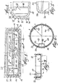
- Figure 1 is an axial section of the improved display-type applicator-containing pot of the present invention, comprising basically a composite jar and closure therefor.
- Fig. 2 is a fragmentary section, greatly enlarged, of the peripheral portion of the inner component of the container of Fig. 1.
- Fig. 3 is an axial section of the inner component or liner of the container of Fig. 1.
- Fig. 4 is a top plan view of the inner component of the container.
- Fig. 5 is a fragmentary section, greatly enlarged, of the peripheral portion of the closure cap part of the pot.
- Fig. 6 is an axial sectional view of the closure cap part of the pot.
- Fig. 7 is a top plan view of the closure cap part of the pot.
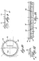
- Fig. 8 is an axial sectional view of the pot, with the closure cap part removed and with the swivel tray in its open position.
- Fig. 9 is a diametric section of the lens or lid window of the closure cap part of the pot.
- Fig. 10 is a top plan view of the lens of Fig. 9.
- Fig. 11 is a fragmentary section, greatly enlarged, of the peripheral portion of the lens of Fig. 9 shown by the broken circle in this figure.
- Fig. 12 is an axial section of the outer container component of the pot.
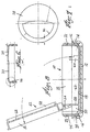
- Fig. 13 is a perspective view of a platform member for incorporation in the pot, as provided by the invention.
- Fig. 14 is a top plan view of the platform member of Fig. 13, and
- Fig. 15 is a bottom plan view of the platform member of Figs. 13 and 14.
-
- Referring first to Figs. 1 and 2 there is illustrated a composite or two-part container for cosmetics or other material, designated generally by the numeral 10 and comprising essentially a shallow outer jacket having a
bottom wall 12 and anannular side wall 14, which latter forms a wide neck portion that, in accordance with the invention, is provided with a plurality of annularinternal grooves 16. Also, in accordance with the present invention there is provided a novel yieldable plastic inner jar component orliner 18, preferably made of a polyolefin, that has connected to it midway up on its lower peripheral portion a depending resilient skirt 19 provided with a plurality of outerannular ribs 20 which can fit snugly in thegrooves 16 of thewall 14 by a snap fit, to lock theliner 18 into the outer orjacket component 12. The skirt 19 is connected to theliner 18 by a web 21, which gives added flexibility and resilience to the skirt and enables the desired press-fit into thejacket wall 14 to be readily effected, and this is an important feature of the invention. - The
liner 18 has an upstandingannular wall 22 that is provided withexternal screw threads 24 for cooperation with matinginternal threads 26 of a shallow, cup-shapedscrew cap 28, Figs. 1 and 5-7. Thelower container assemblage 10 can thus be tightly closed by thescrew cap 28, as shown in Fig. 1. - The
screw cap 28 has a half-moon shaped opening orwindow 30, Figs. 6 and 7, in which there is mounted alens 32 of aliner member 34, Figs. 9 and 10. Theliner member 34 hasunderside sealing areas 36 which are engageable with the lip of theneck portion 22 of thejar liner 18, to provide a hermetic seal therewith. - Referring to Fig. 2, in carrying out the sealing function, the periphery or
peripheral wall 22 of theliner 18 is provided with anupstanding bead 38 which is engageable with the under-surface of theliner member 34, and the latter had an annularsharp bead 40 which is engageable with the inside of the rim or lip of thewall 22 of theliner 18. The result is an essentially completely air-tight or hermetic sealing engagement with the jar lip andwall 22. The sealing pressure from theclosure cap 28 is transmitted to the lens-liner member 34 as the cap is screwed down tightly on thewall 22, as will now be understood. Advantageously, theliner 18 can be constituted of yieldable polyolefin plastic. - With the closure screw cap being constituted of the two ultrasonically joined
pieces liner piece 34 and the jar lip orwall 22, with the periphery of thescrew cap 28 lying radially outside of the sealing area and as such, not participating in the sealing function except to retain the pressure on theliner piece 34. - The
transparent lens 32 not only facilitates inspection of the container contents, but in addition themember 34 having the lens is solely responsible for the seal with thejar lip 22. As noted, the seal is accomplished between solely two molded components, each of which is integral in and of itself and thus air-tight, namely theliner 18 and the lens-liner 34. The opaque characteristic of thescrew cap 28 has a distinct advantage from the aesthetics standpoint, since it fully conceals thethread 24 of thejar wall 22 as well as concealing its owninternal thread 26. In accomplishing the concealment, the peripheral portion of thescrew cap 28 extends radially inwardly of thewall 22, such that the said peripheral portion, being opaque, hides thecooperable threads transparent lens 32 at an angle. All that is visible is the product itself (not shown), and the inner surfaces of theside wall 22 of theliner 18. - According to the present invention, in conjunction with the above structures there is provided a unique swivel-
type circular platform 42 within the upper portion of theliner 18. Referring to Figs. 3 and 4, theliner 18 has an upstanding yieldable trunnion mounting 44 comprisingwalls walls notches 52 to accept thepintle 54 of the platform 42 (Figs. 13-15) . Theplatform 42 has an upstandingperipheral flange 56 to enable it to function as a shallow tray for cosmetic product (not shown), and has on its under side acircular flange 58 to provide support when it is folded and disposed within the pot. For this latter purpose, theliner 18 has a pair of resilient shoulders or support portions 60 (Fig. 8). - As shown in Fig. 1, a
space 62 exists beneath theplatform 42, to store an applicator such as a powder puff (not shown) or the like. Theunderside 64 of theplatform 42 can be constituted as a mirror surface, for use when the cosmetic is to be applied by the user. In Fig. 12 theouter jacket 12 is shown as having a plurality ofvertical friction ribs 66 which are forcibly engageable with the exterior of theliner 18 to prevent incidental rotation of the latter. - From the above it can be seen that we have provided a novel and improved display-type applicator-containing pot or compact which is both simple in its structure, and which features improved seal characteristics that are confined essentially to the container lip, and solely inner parts of the composite pot assemblage, namely the inner liner portions thereof. Conventional cap liners of the type which have been employed in the past, are not required. Where the upper liner is made transparent, the contents of the container can be readily viewed; also, where the screw cap member is constituted of opaque plastic, all the threads of the container are completely concealed from view, this latter feature being considered very important from the commercial standpoint.
- An exemplar variation constitutes a completely opaque closure with the applicator occupying the top level of the inner chamber atop the swivel platform or tray, and the product storage occupying the space beneath the swivel platform or tray. The bottom of the platform or tray serves as the mirror-reflecting surface when the platform or tray swings up to its utility position.
- As an alternative, the screw cap member can be a solid, opaque, one-piece design, having the desired air-tight characteristics. Also, the cosmetic product can occupy either the tray or the bottom wall area of
liner 18. Similarly, an applicator or puff can occupy one of either the tray or the bottom wall area ofliner 18. - As a further alternative, the
platform 42 can be a hinge design or other type of design, such as a simple stacking design. - The disclosed structure is thus seen to represent a distinct advance and improvement in the dispenser field.
- Variations and modifications are possible without departing from the spirit of the invention.
- Each and every one of the appended claims defines an aspect of the invention which is separate and distinct from all others, and accordingly it is intended that each claim be treated in this manner when examined in the light of the prior art devices in any determination of novelty or validity.
Claims (21)
- A display-type applicator-containing compact for cosmetics and the like, comprising, in combination:a) a shallow jar having a wide neck portion provided with external screw threads, said neck portion having at its rim a continuous sealing lip,b) a screw cap member that is cooperable with said neck portion, said cap member having internal screw threads that engage the external screw threads of the neck portion, and having a window in its top,c) a plastic liner member disposed under the screw cap member, said liner member having sealing portions which are engageable with the sealing lip of said neck portion and with the underside of the cap member,d) said liner member having a lens portion which occupies the window of the screw cap to permit a user to see the interior of the jar, ande) a swivel tray pivotally mounted in the jar and swingable up and out of the jar when the screw cap is removed,f) said tray being adapted to hold cosmetic material which can be viewed through the lens portion of the liner member.
- A display-type applicator-containing compact as set forth in claim 1, wherein:a) said jar comprises an inner container member and an outer jacket which surrounds the lower portions of said container member,b) said jacket and container member being constituted of dissimilar plastic materials which have different physical yieldability characteristics.
- A display-type applicator-containing compact as set forth in claim 2, wherein:a) said screw cap member and outer jacket have substantially aligned peripheral walls.
- A display-type applicator-containing compact as set forth in claim 2, wherein:a) said container member has means providing a swivel saddle which is cooperable with the said swivel tray to provide a pivotal mounting therefor.
- A display-type applicator-containing compact as set forth in claim 2, wherein:a) said container member has means providing a resilient support for the said swivel tray when the latter is disposed in the container member.
- A display-type applicator-containing compact as set forth in claim 4, wherein:a) the swivel tray has a trunnion which is laterally receivable in the said swivel saddle.
- A display-type applicator-containing compact as set forth in claim 2, wherein:a) said inner container member and said liner member are constituted of a polyolefin.
- A display-type applicator-containing compact as set forth in claim 1, wherein:a) said swivel tray has a peripheral top flange to provide a barrier for confining the cosmetics, and has a bottom circular flange to provide a support surface when the tray is in the container member.
- A display-type applicator-containing compact as set forth in claim 8, wherein:a) the swivel tray has a mirror means disposed within the said bottom circular flange.
- A display-type applicator-containing compact as set forth in claim 1, wherein:a) said screw cap member has a window-like opening in its top surface, andb) said plastic liner member has a transparent window spanning the said window opening.
- A display-type applicator-containing compact as set forth in claim 5, wherein:a) the said resilient support means for the swivel tray comprises upstanding shoulders in the container member, in the form of thin-section walls.
- A display-type applicator-containing compact for cosmetics and the like, comprising, in combination:a) a shallow jar having a wide neck portion provided with external screw threads, said neck portion having at its rim a continuous sealing lip,b) a screw cap member that is cooperable with said neck portion, said cap member having internal screw threads that engage the external screw threads of the neck portion,c) an outer jacket surrounding the lower portions of said jar,d) said jar and outer jacket being constituted of dissimilar plastic materials which have different yieldability characteristics,f) said jacket being press-fitted over said jar.
- A display-type applicator-containing compact as set forth in claim 12, wherein:a) said shallow jar comprises an inner container member and an outer jacket,b) said inner container member having a threaded neck portion which protrudes beyond the top rim of the said jacket.
- A display-type applicator-containing compact as set forth in claim 12, wherein:a) said inner container member and outer jacket having interlocking means comprising ribs and grooves receiving the ribs, to maintain the jacket in place on the container member.
- A display-type applicator-containing compact as set forth in claim 14, wherein:a) said inner container member has a depending skirt which engages the inner surface of the jacket,b) said depending skirt being connected to the inner container member by a thin, resilient web.
- A display-type applicator-containing compact as set forth in claim 13, wherein:a) the inner container member has resilient support means for positioning a swivel tray,b) said resilient support means comprising upstanding shoulders in the container member, said shoulders comprising thin-section walls.
- A display-type applicator-containing compact as set forth in claim 13, wherein:a) said inner container member has the screw threads of the jar.
- A display-type applicator-containing compact as set forth in claim 13, wherein:a) the inner container member has stops for engagement with a swivel trayb) said stops comprising thin-section walls.
- A display-type applicator-containing compact as set forth in claim 12, wherein:a) the inner container member comprises a polyolefin plastic.
- A display-type applicator-containing compact for cosmetics and the like, comprising, in combination:a) a shallow jar having a wide neck portion provided with external screw threads, said neck portion having at its rim a continuous sealing lip,b) a screw cap member that is cooperable with said neck portion, said cap member having internal screw threads that engage the external screw threads of the neck portion,c) a plastic liner member disposed under the screw cap member, said liner member having sealing portions which are engageable with the sealing lip of said neck portion and with the underside of the cap member, andd) a swivel tray pivotally mounted in the jar and swingable up and out of the jar when the screw cap is removed,e) said tray being adapted to hold cosmetic material or a puff.
- A display-type applicator-containing compact as set forth in claim 4, wherein:a) the swivel tray can be opened to a fixed angle for the convenience of use.
Applications Claiming Priority (2)
| Application Number | Priority Date | Filing Date | Title |
|---|---|---|---|
| US924984 | 1978-07-17 | ||
| US08/924,984 US5884636A (en) | 1997-09-08 | 1997-09-08 | Cosmetic pot with internal hinged tray |
Publications (2)
| Publication Number | Publication Date |
|---|---|
| EP0904712A2 true EP0904712A2 (en) | 1999-03-31 |
| EP0904712A3 EP0904712A3 (en) | 2000-09-27 |
Family
ID=25451033
Family Applications (1)
| Application Number | Title | Priority Date | Filing Date |
|---|---|---|---|
| EP98202978A Withdrawn EP0904712A3 (en) | 1997-09-08 | 1998-09-07 | Cosmetic pot with internal hinged tray |
Country Status (2)
| Country | Link |
|---|---|
| US (1) | US5884636A (en) |
| EP (1) | EP0904712A3 (en) |
Cited By (2)
| Publication number | Priority date | Publication date | Assignee | Title |
|---|---|---|---|---|
| FR2806272A1 (en) * | 2000-03-15 | 2001-09-21 | Yoshida Industry Co | WATERPROOF BOX |
| FR2956953A1 (en) * | 2010-03-08 | 2011-09-09 | Qualipac Sa | HOUSING BASE, HOUSING AND ASSOCIATING METHOD |
Families Citing this family (12)
| Publication number | Priority date | Publication date | Assignee | Title |
|---|---|---|---|---|
| FR2803993B1 (en) * | 2000-01-20 | 2002-06-07 | Lir France Sa | CASES FOR COSMETIC PRODUCTS WITH IMPROVED SEALING |
| US6378533B1 (en) | 2000-10-11 | 2002-04-30 | Augros, Inc. | Cosmetic jar with pivotable pull-out storage device |
| US6769438B2 (en) * | 2002-02-08 | 2004-08-03 | Henlopen Manufacturing Co., Inc. | Dual mirror compact |
| US6712076B2 (en) | 2002-03-12 | 2004-03-30 | Rexam Beauty And Closures Inc. | Shade-evident airtight container |
| JP3834256B2 (en) * | 2002-04-16 | 2006-10-18 | エム・エフ・ヴィ株式会社 | container |
| JP4062596B2 (en) * | 2002-06-28 | 2008-03-19 | ザ プロクター アンド ギャンブル カンパニー | Storage container |
| US20050023183A1 (en) * | 2003-07-29 | 2005-02-03 | Joachim Banik | Hermetically sealed container |
| US20060054517A1 (en) * | 2004-09-15 | 2006-03-16 | Rexam Beauty And Closures, Inc. | Wipe storage system |
| USD600857S1 (en) | 2007-11-19 | 2009-09-22 | Mary Kay Inc. | Container |
| USD599551S1 (en) | 2007-11-20 | 2009-09-08 | Mary Kay Inc. | Container |
| EP2548466B1 (en) * | 2010-03-18 | 2016-04-13 | Yong Jun Lee | Sealing ring structure of a cosmetic container |
| KR200483051Y1 (en) * | 2015-06-23 | 2017-03-30 | 코코스팩 주식회사 | Cosmetics case |
Citations (11)
| Publication number | Priority date | Publication date | Assignee | Title |
|---|---|---|---|---|
| US209813A (en) | 1878-11-12 | Improvement in jelly-glasses | ||
| US326492A (en) | 1885-09-15 | Cap for fruit-jars | ||
| US597083A (en) | 1898-01-11 | Fruit-jar and cover for same | ||
| US748642A (en) | 1904-01-05 | Charles habold nicholson | ||
| US893008A (en) | 1908-03-31 | 1908-07-14 | Anthony F Mcdonnell | Bottle and cap-closure. |
| US997505A (en) | 1910-11-22 | 1911-07-11 | Hermann Op De Hipt | Jar-closure. |
| US1516129A (en) | 1922-11-23 | 1924-11-18 | Ralph Seddon | Gasket guard |
| US1700958A (en) | 1926-08-27 | 1929-02-05 | Vacuum Seal Co Inc | Vacuum-sealed jar |
| US3111237A (en) | 1960-07-25 | 1963-11-19 | Foster M Hagmann | Seal for jar caps |
| US3428208A (en) | 1967-04-10 | 1969-02-18 | John Kosar | Direct seals between receptacles and closures therefor |
| US4834824A (en) | 1988-01-20 | 1989-05-30 | Preform Sealants, Inc. | Method of making a foamed-in-place gasket |
Family Cites Families (14)
| Publication number | Priority date | Publication date | Assignee | Title |
|---|---|---|---|---|
| US1456636A (en) * | 1922-08-30 | 1923-05-29 | Henri Ricaud | Vanity case |
| US1651193A (en) * | 1927-06-01 | 1927-11-29 | Arron R Chisholm | Vanity case |
| US2401127A (en) * | 1945-07-21 | 1946-05-28 | James L Younghusband | Make-up and sponge container |
| US3911936A (en) * | 1974-01-14 | 1975-10-14 | Plough | See-through cosmetic package |
| US3996947A (en) * | 1975-11-10 | 1976-12-14 | Fashion Optics, Inc. | Make-up kit |
| FR2414311A1 (en) * | 1978-01-12 | 1979-08-10 | Saint Laurent Parfums Yves | Cosmetic case with lid and body - joined by hinged frames which fit into them to be held by rivets |
| IT8221137U1 (en) * | 1982-03-15 | 1983-09-15 | Inca Srl | COSMETICS CONTAINER WITH MAGNIFYING GLASS. |
| IT8320651U1 (en) * | 1983-01-31 | 1984-07-31 | Inca Srl | Container especially for cosmetics, equipped with a perfected device for sealing. |
| IT1177629B (en) * | 1983-03-30 | 1987-08-26 | Estee Lauder Inc | AIR HERMETIC CONTAINER |
| US4972860A (en) * | 1987-09-11 | 1990-11-27 | Yoshida Industry Co., Ltd. | Vanity case |
| FR2693882B1 (en) * | 1992-07-24 | 1994-10-07 | Lir France Sa | Makeup powder dispenser jar. |
| US5431177A (en) * | 1993-11-03 | 1995-07-11 | Sussex Plastics Inc. | Compact having a window |
| US5542561A (en) * | 1994-10-17 | 1996-08-06 | Jerhel Plastics, Inc. | Compact or container with attached cap and optional airtight closure |
| IT1287401B1 (en) * | 1996-02-29 | 1998-08-06 | Bormioli Metalplast Spa | CAPSULE FOR CLOSING CONTAINERS |
-
1997
- 1997-09-08 US US08/924,984 patent/US5884636A/en not_active Expired - Lifetime
-
1998
- 1998-09-07 EP EP98202978A patent/EP0904712A3/en not_active Withdrawn
Patent Citations (11)
| Publication number | Priority date | Publication date | Assignee | Title |
|---|---|---|---|---|
| US209813A (en) | 1878-11-12 | Improvement in jelly-glasses | ||
| US326492A (en) | 1885-09-15 | Cap for fruit-jars | ||
| US597083A (en) | 1898-01-11 | Fruit-jar and cover for same | ||
| US748642A (en) | 1904-01-05 | Charles habold nicholson | ||
| US893008A (en) | 1908-03-31 | 1908-07-14 | Anthony F Mcdonnell | Bottle and cap-closure. |
| US997505A (en) | 1910-11-22 | 1911-07-11 | Hermann Op De Hipt | Jar-closure. |
| US1516129A (en) | 1922-11-23 | 1924-11-18 | Ralph Seddon | Gasket guard |
| US1700958A (en) | 1926-08-27 | 1929-02-05 | Vacuum Seal Co Inc | Vacuum-sealed jar |
| US3111237A (en) | 1960-07-25 | 1963-11-19 | Foster M Hagmann | Seal for jar caps |
| US3428208A (en) | 1967-04-10 | 1969-02-18 | John Kosar | Direct seals between receptacles and closures therefor |
| US4834824A (en) | 1988-01-20 | 1989-05-30 | Preform Sealants, Inc. | Method of making a foamed-in-place gasket |
Cited By (2)
| Publication number | Priority date | Publication date | Assignee | Title |
|---|---|---|---|---|
| FR2806272A1 (en) * | 2000-03-15 | 2001-09-21 | Yoshida Industry Co | WATERPROOF BOX |
| FR2956953A1 (en) * | 2010-03-08 | 2011-09-09 | Qualipac Sa | HOUSING BASE, HOUSING AND ASSOCIATING METHOD |
Also Published As
| Publication number | Publication date |
|---|---|
| US5884636A (en) | 1999-03-23 |
| EP0904712A3 (en) | 2000-09-27 |
Similar Documents
| Publication | Publication Date | Title |
|---|---|---|
| US5791506A (en) | Sealing container which includes a two-part cap for displaying a cosmetic product | |
| US5884636A (en) | Cosmetic pot with internal hinged tray | |
| US5186318A (en) | Air tight container | |
| US6712076B2 (en) | Shade-evident airtight container | |
| CA2472978C (en) | Container with double lids | |
| US6029842A (en) | Cosmetic jar with transparent cover and hidden threads | |
| US4917131A (en) | Latch assembly and front release mechanism for compacts and other containers | |
| JP3878413B2 (en) | Airtight container | |
| EP1072532B1 (en) | Combination container | |
| US6055992A (en) | Shatterproof cosmetic compact | |
| US7819125B2 (en) | Case for packaging a product | |
| US20060254945A1 (en) | Spherical container with lid insert | |
| US20040173498A1 (en) | Multifunctional compact mirror case | |
| US20230218064A1 (en) | Cosmetic container having button-separable structure | |
| US20020170915A1 (en) | Closure with secondary compartment | |
| JP3432155B2 (en) | Makeup box | |
| GB2137594A (en) | Air-tight container | |
| WO2007064072A1 (en) | Container for toiletry | |
| US11812841B2 (en) | Cosmetic container with contents visible from outside | |
| CN114291414A (en) | One-key lid with decorative portion | |
| JP2748112B2 (en) | Closed container | |
| JPH0122567Y2 (en) | ||
| KR102879975B1 (en) | Container | |
| CN218418818U (en) | Cosmetic product packaging bottle | |
| JP2598823Y2 (en) | Sealed compact container |
Legal Events
| Date | Code | Title | Description |
|---|---|---|---|
| PUAI | Public reference made under article 153(3) epc to a published international application that has entered the european phase |
Free format text: ORIGINAL CODE: 0009012 |
|
| AK | Designated contracting states |
Kind code of ref document: A2 Designated state(s): DE ES FR GB IT |
|
| AX | Request for extension of the european patent |
Free format text: AL;LT;LV;MK;RO;SI |
|
| RIC1 | Information provided on ipc code assigned before grant |
Free format text: 7A 45D 33/00 A, 7B 65D 41/34 B |
|
| PUAL | Search report despatched |
Free format text: ORIGINAL CODE: 0009013 |
|
| AK | Designated contracting states |
Kind code of ref document: A3 Designated state(s): AT BE CH CY DE DK ES FI FR GB GR IE IT LI LU MC NL PT SE |
|
| AX | Request for extension of the european patent |
Free format text: AL;LT;LV;MK;RO;SI |
|
| RAP1 | Party data changed (applicant data changed or rights of an application transferred) |
Owner name: CHANG, CHARLES |
|
| RIN1 | Information on inventor provided before grant (corrected) |
Inventor name: CHANG, CHARLES Inventor name: SHEFFLER, J. ROBERT |
|
| 17P | Request for examination filed |
Effective date: 20010316 |
|
| AKX | Designation fees paid |
Free format text: DE ES FR GB IT |
|
| STAA | Information on the status of an ep patent application or granted ep patent |
Free format text: STATUS: THE APPLICATION IS DEEMED TO BE WITHDRAWN |
|
| 18D | Application deemed to be withdrawn |
Effective date: 20020403 |