EP0904515B1 - Gerät zur rückgewinnung und speicherung vom abgekühltem wasser in warmwasserrohren mit einstellbarer thermostatregelung - Google Patents
Gerät zur rückgewinnung und speicherung vom abgekühltem wasser in warmwasserrohren mit einstellbarer thermostatregelung Download PDFInfo
- Publication number
- EP0904515B1 EP0904515B1 EP97921155A EP97921155A EP0904515B1 EP 0904515 B1 EP0904515 B1 EP 0904515B1 EP 97921155 A EP97921155 A EP 97921155A EP 97921155 A EP97921155 A EP 97921155A EP 0904515 B1 EP0904515 B1 EP 0904515B1
- Authority
- EP
- European Patent Office
- Prior art keywords
- water
- hot water
- pump
- valve
- hydraulic motor
- Prior art date
- Legal status (The legal status is an assumption and is not a legal conclusion. Google has not performed a legal analysis and makes no representation as to the accuracy of the status listed.)
- Expired - Lifetime
Links
- XLYOFNOQVPJJNP-UHFFFAOYSA-N water Substances O XLYOFNOQVPJJNP-UHFFFAOYSA-N 0.000 title claims abstract description 388
- 238000005086 pumping Methods 0.000 claims abstract description 18
- 238000000034 method Methods 0.000 claims description 5
- 230000006835 compression Effects 0.000 description 4
- 238000007906 compression Methods 0.000 description 4
- 238000001816 cooling Methods 0.000 description 3
- 230000013011 mating Effects 0.000 description 3
- 210000002445 nipple Anatomy 0.000 description 3
- 239000002699 waste material Substances 0.000 description 3
- 238000005553 drilling Methods 0.000 description 2
- VNWKTOKETHGBQD-UHFFFAOYSA-N methane Chemical compound C VNWKTOKETHGBQD-UHFFFAOYSA-N 0.000 description 2
- 238000010926 purge Methods 0.000 description 2
- 239000010865 sewage Substances 0.000 description 2
- SZKKRCSOSQAJDE-UHFFFAOYSA-N Schradan Chemical class CN(C)P(=O)(N(C)C)OP(=O)(N(C)C)N(C)C SZKKRCSOSQAJDE-UHFFFAOYSA-N 0.000 description 1
- 235000012206 bottled water Nutrition 0.000 description 1
- 238000004891 communication Methods 0.000 description 1
- 230000008602 contraction Effects 0.000 description 1
- 230000001419 dependent effect Effects 0.000 description 1
- 239000003651 drinking water Substances 0.000 description 1
- 230000005611 electricity Effects 0.000 description 1
- 238000002474 experimental method Methods 0.000 description 1
- 239000007788 liquid Substances 0.000 description 1
- 239000000463 material Substances 0.000 description 1
- 238000012986 modification Methods 0.000 description 1
- 230000004048 modification Effects 0.000 description 1
- 239000003345 natural gas Substances 0.000 description 1
- 230000005855 radiation Effects 0.000 description 1
- 230000004043 responsiveness Effects 0.000 description 1
- 239000011343 solid material Substances 0.000 description 1
- 230000003068 static effect Effects 0.000 description 1
- 230000007704 transition Effects 0.000 description 1
Images


Classifications
-
- F—MECHANICAL ENGINEERING; LIGHTING; HEATING; WEAPONS; BLASTING
- F24—HEATING; RANGES; VENTILATING
- F24D—DOMESTIC- OR SPACE-HEATING SYSTEMS, e.g. CENTRAL HEATING SYSTEMS; DOMESTIC HOT-WATER SUPPLY SYSTEMS; ELEMENTS OR COMPONENTS THEREFOR
- F24D17/00—Domestic hot-water supply systems
- F24D17/0094—Recovering of cold water
-
- Y—GENERAL TAGGING OF NEW TECHNOLOGICAL DEVELOPMENTS; GENERAL TAGGING OF CROSS-SECTIONAL TECHNOLOGIES SPANNING OVER SEVERAL SECTIONS OF THE IPC; TECHNICAL SUBJECTS COVERED BY FORMER USPC CROSS-REFERENCE ART COLLECTIONS [XRACs] AND DIGESTS
- Y10—TECHNICAL SUBJECTS COVERED BY FORMER USPC
- Y10T—TECHNICAL SUBJECTS COVERED BY FORMER US CLASSIFICATION
- Y10T137/00—Fluid handling
- Y10T137/0318—Processes
- Y10T137/0324—With control of flow by a condition or characteristic of a fluid
-
- Y—GENERAL TAGGING OF NEW TECHNOLOGICAL DEVELOPMENTS; GENERAL TAGGING OF CROSS-SECTIONAL TECHNOLOGIES SPANNING OVER SEVERAL SECTIONS OF THE IPC; TECHNICAL SUBJECTS COVERED BY FORMER USPC CROSS-REFERENCE ART COLLECTIONS [XRACs] AND DIGESTS
- Y10—TECHNICAL SUBJECTS COVERED BY FORMER USPC
- Y10T—TECHNICAL SUBJECTS COVERED BY FORMER US CLASSIFICATION
- Y10T137/00—Fluid handling
- Y10T137/6416—With heating or cooling of the system
- Y10T137/6497—Hot and cold water system having a connection from the hot to the cold channel
-
- Y—GENERAL TAGGING OF NEW TECHNOLOGICAL DEVELOPMENTS; GENERAL TAGGING OF CROSS-SECTIONAL TECHNOLOGIES SPANNING OVER SEVERAL SECTIONS OF THE IPC; TECHNICAL SUBJECTS COVERED BY FORMER USPC CROSS-REFERENCE ART COLLECTIONS [XRACs] AND DIGESTS
- Y10—TECHNICAL SUBJECTS COVERED BY FORMER USPC
- Y10T—TECHNICAL SUBJECTS COVERED BY FORMER US CLASSIFICATION
- Y10T137/00—Fluid handling
- Y10T137/8593—Systems
- Y10T137/85978—With pump
- Y10T137/86171—With pump bypass
Definitions
- the invention relates to an apparatus for pumping cold water in a hot water line into a cold water line, comprising:
- the invention also releates to a method of conserving water by connecting a water pump between a hot water line and a cold water line and pumping cold water in the hot water line into the cold water line when hot water is desired from a hot water tap connected to the hot water line and water in the hot water line is below a predetermined temerature.
- demand-type water heater located close to the tap.
- Multiple demand-type water heaters are often required if water wastage is to be eliminated because the various taps are not always located close to each other.
- demand-type water heaters are usually electric water heaters and are significantly lass efficient than natural gas fired heates of the storage tank type.
- Another method for reducing the amount of water wasted while purging pipes is the continuosly circulating hat water system.
- the pipes leading from the hot water heater are arranged in a loop, passing near each tap, with a return pipe to the hot water heater.
- a pump is inserted in the loop to keep hot water flowing through the loop, thereby keeping the pipes and the water in them at a high temperature.
- This system is less energy efficient than the typical system because of the heat radiation from the pipes, and is difficult to retrofit to existing buildings. This systam is nonetheless common in large buildings with many bathrooms such as hospitals.
- U.S. Patent No. 5,277,219 shows a water saving hot water system wherein an electric pump is used to pump ambient temperature, cool water from the hot water pipe into the cold water pipe. A switch is pressed to turn on the pump when hot water is desired. The pump turns off when a temperature sensor detects that the cool water has been purged from the hot water pipe.
- Yet another such system is portrayed by U.S. Patent No. 5,009,572, issued to Imhoff on April 23, 1991.
- this object is achieved with an apparatus wherein the apparatus additionally includes a hydraulic motor and a hot water outlet; the water pump is actuated by the hydraulic motor; the valve has one position wherein the water is allowed to flow from the hot water inlet to the hot water outlet bypassing the hydraulic motor and pump; and the temperature sensing element for sensing the temperature of water flowing into the apparatus from the hot water inlet controls the valve, whereby the valve directs water to the hydraulic motor and pump when the temperature of the water flowing into the apparatus from the hot water inlet is below the preset temperature, and allows flow of the water from the hot water inlet to the hot water outlet bypassing the hydraulic motor and pump when the water flowing into the apparatus from the hot water inlet is above the preset temperature.
- the method of the invention is characterized by the steps of connecting a water pump which is operated by a hydraulic motor between the hot water line and the cold water line near the hot water tap where hot water is desired; directing water from the hot water line through the hydraulic motor to operate the water pump when the hot water tap is opened to obtain hot water, the water pump thereby pumping a portion of the water that would normally flow from the open tap into the cold water line so that only a portion of the normal flow flows from the hot water tap; sensing when the water in the hot water line near the tap reaches a predetermined temperature; and stopping the pump and allowing normal flow of water from the hot water tap when the sensed temerature of the water near the tap reaches the predetermined temperature.
- a hydraulically powered pump is provided to pump cool water from the hot water pipe to the cold water pipe until water in the hot water pipe reaches a desired temperature.
- the pump is powered by allowing some of the water from the hot water pipe to escape through the hot water tap. This escaping water, usually about one-quarter the normal flow from the tap, is sufficient to pump the remaining about three-quarters of the normal flow from the hot water pipe into the cold water pipe. Thus, about seventy-five percent of the water normally wasted is saved. The twenty-five percent which does flow out of the tap to power the pump will generally represent a lower resource use than the electricity used by an electric pump to save all of the water.
- the device of the invention is self-contained and easier to install and use than a system that requires electrical power.
- a preferred embodiment of the invention uses a hydraulic gear motor and gear pump to recover about 75% of the cool water that would otherwise be discarded.
- About one-fourth of the water flow from the hot water pipe runs through the gear motor, around a bimetallic thermostat element which controls a flow control valve, and is vented out the tap. This flow drives the gear pump that pumps the remaining about 75% of the flow from the hot water pipe into the cold water pipe.
- the bimetallic thermostat element operates a valve to permit all of the water in the hot water pipe to flow from the tap.
- a control permits adjustment of the temperature at which the bimetallic thermostat element turns the valve.
- the water saving device of the present invention is connected in the hot and cold water lines leading to hot and cold water taps.
- the hot water tap When the hot water tap is turned on and water in the hot water line at the device has cooled so is not at a desired hot temperature, a small portion of the water from the hot water line which usually flows from the tap flows through a hydraulic motor and out the tap.
- the hydraulic motor operates a pump to pump the larger portion of the water which usually flows from the tap into the cold water line. This continues until the water in the hot water line at the device has reached a preset temperature at which time full flow of water from the hot water tap is restored.
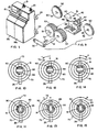
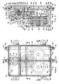
- the water saving device of the illustrated embodiment includes housing 18 formed of housing halves 19a and 19b, Fig. 1, having a hot water inlet 20, Figs. 2, 3, 16, and 17, a hot water outlet 21, a cold water inlet 22, and a cold water outlet 23.
- a pair of mounting lugs 24 extend from each side of housing 18 whereby the device may be mounted to a wall or other surface.
- a temperature adjustment knob 25 extends from the housing to be accessible by a user.
- the device of the invention is mounted close to a sink, basin, tub, shower, or other location where hot and cold water is normally used, and the device is connected in the hot and cold water lines.
- the device may be mounted on a building wall or the back wall of a cabinet under a kitchen sink or bathroom basin.
- the hot water inlet 20 is connected to the hot water supply pipe (not shown) conducting water from the hot water outlet of a storage tank type water heater (not shown), and the hot water outlet 21 is connected to the hot water tap (not shown).
- the cold water inlet 22 is connected to the cold water supply pipe (not shown) that is generally also connected to the cold water inlet of the water heater (not shown).
- the cold water outlet 23 is connected to the cold water tap (not shown).
- the housing halves 19a and 19b may be formed of solid material, such as plastic, with various flow passages and receiving compartments molded or milled and drilled therein.
- each of the halves 19a and 19b will have mating passage halves molded into the mating surface of the halves so that when the halves are joined together they form a hot water through passage 26, a lower hot water bypass passage 27 extending from the hot water through passage 26 and having outlet branches 28 and 29 opening into a compartment 30 adapted to receive a hydraulic motor and pump assembly therein, an upper hot water bypass passage 31 extending from compartment 30 to a compartment 32, opening 33 connecting compartment 32 to hot water through passage 26, and stub passage 34 extending a short distance from compartment 30 opposite branch 29.
- Housing half 19b additionally has a cold water through passage 35 formed therein, such as by drilling, with a passage 36, see particularly Figs. 4 and 7, extending from stub passage 34 to connection with passage 37 to connect stub passage 34 to cold water through passage 35.
- These passages 36 and 37 may be drilled into half 19b from the outside with portions 36a and 37a, Fig. 4, being filled in or otherwise plugged after drilling.
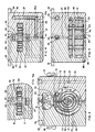
- the hydraulic motor and pump assembly of the illustrated embodiment comprise a gear type motor and a gear type pump.
- a gear type motor requires that the teeth of two meshing gears form a seal. Water under pressure is introduced into the space between the gears as they move apart, filling the space between the teeth. Water is released into a lower pressure outlet from the space where the teeth move together.
- the hydraulic motor and pump assembly includes a bearing body 45 with pairs of shaft mounting holes 46 at opposite sides of the body, a motor gear compartment 47, and a pump gear compartment 48.
- Motor gears 50 are placed in the motor gear compartment 47, and keyed to respective axles 51 with keys 52.
- a pair of pump gears 53 are keyed to the same axles 51 with keys 54 such that rotation of the motor gears will cause rotation of the pump gears.
- a securing strap 56 is attached over the ends of the axles to hold the axles at the correct distance from each other and form end bearings.
- the motor and pump assembly is installed within appropriately shaped receiving compartment 30 in housing halves 19a and 19b, with the housing halves locating and holding strap 56 in proper position, see Figs. 3 and 5.
- bearing body 45 includes a motor inlet opening 60, Figs. 3 and 8, which, with bearing body 45 inserted in receiving compartment 30, is aligned and in flow communication with bypass branch passage 28 in body halves 19a and 19b.
- bearing body 45 has a motor outlet opening 61, Figs. 3, 8 and 9, which is aligned with bypass passage 31, a pump inlet opening 62 which is aligned with bypass branch 29, Figs. 3, 7 and 9, and a pump outlet opening 63 aligned with stub passage 34.
- pump gears 53 are wider than motor gears 50.
- the relative widths of the gears determine generally the proportion of water flow through each. If the pump gears and motor gears are of equal width, approximately the same amount of water will flow through the pump and through the motor. With the pump gears three times the width of the motor gears, as presently preferred, about a third as much water passes through the pump as through the motor. This results in the flow through the motor being about one-quarter of the total combined flow through the motor and the pump. Gear widths and flow proportions can be adjusted as desired.
- Housing halves 19a and 19b include on their mating faces grooves which form a receiving passage 64, Figs. 8 and 8a, for rotatably receiving a cylindrical valve spool member 65 which extends through receiving compartment 32 and into hot water through passage 26 on one side of compartment 32 and upper bypass passage 31 on the opposite side of compartment 32.
- Valve spool member 65 includes a passage 66 therethrough in the portion thereof aligned with hot water through passage 26 and a passage 67 extending through the portion thereof aligned with upper bypass passage 31.
- Valve spool member passages 66 and 67 while in parallel planes, extend in different directions. As shown, passage 66 extends in a direction rotated 90° from the direction of passage 67.
- valve spool member 65 when valve spool member 65 is rotated so that spool member passage 67 is aligned with upper bypass passage 31 as shown in Fig. 3 to thereby open and allow flow through passage 31, spool member passage 66 is not aligned with hot water through passage 26 so that such passage 26 is blocked or closed.
- valve spool member 65 is rotated 90° so that spool member passage 66 is aligned with hot water through passage 26 to open and allow flow through passage 26, Fig. 3a, spool member passage 67 is not aligned with upper bypass passage 31 so that such passage 31 is blocked or closed.
- Valve spool member 65 is rotated and controlled by a helical bimetallic thermostat spring element 70, see particularly Figs. 3 and 6, attached at its inner end to a central reduced diameter portion 71 of valve member 65 and having a rack segment 72 attached to its outer end, as by rivets 73.
- Rack segment 72 includes arcuate grooves 75 on opposite sides thereof and housing halves 19a and 19b include recesses 76 in which positioning pins 77 are placed to extend from housing halves 19a and 19b into grooves 75 to hold rack segment 72 in position at a fixed radius from the central axis of valve member 65.
- the position of rack segment 72 and the attached end of bimetallic thermostat element 70 may be adjusted by temperature adjustment knob 25.
- Knob 25 has a shaft 80 extending therefrom and extending rotatably through a receiving passage 81 in body halves 19a and 19b.
- a sector gear 83 is mounted in the upper portion of receiving compartment 32 and is attached to knob shaft 80 so that it rotates with temperature control knob 25. Rotation of temperature control knob 25 causes rotation of sector gear 83.
- Sector gear 83 meshes with rack segment 72 so that rotation of sector gear 83 causes rack segment 72 to move in an arc guided by pins 77 in grooves 75.
- rotation of knob 25 causes movement of the rack segment 72 and the end of bimetallic thermostat spring element 70 attached thereto between a central position shown in Figs. 6, 10, and 11, a counterclockwise rotated position as shown in Figs.
- a spring loaded holding element 85 Fig. 3, mounted in opening 86 and biased toward sector gear 83 by spring 87, cooperates with depressions 88, Fig. 6, in the face of sector gear 83 to hold such gear in rotated or central positions. Additional depressions could be provided to hold sector gear 83 in adjusted positions between the extremes shown.
- a stop pin 90 Fig. 6 and 10-15, extends from housing half 19a into a slot 91, Figs.3, 4a, 6, and 10-15, in valve member 65 to limit the rotation of valve member 65 to 90° and stop rotation in one direction when spool passage 67 is aligned with upper bypass passage 31 as shown in Fig.
- thermostat spring element 70 While adjustability of the thermostat spring element 70 is presently preferred, it is not necessary. The positioning of the outer end of spring element 70 could be fixed in a factory set position to operate the valve to open hot water passage 26 in a factory set temperature range.
- rack segment 72 is shown as slidably positioned and held at a constant radius from the central axis of valve spool member 65 by pins 77 in grooves 75, the rack segment could be positioned by extending supporting side segments from the sides of the rack to valve spool member 65 on both sides of the bimetallic thermostat element 70. Such sides would be rotatable mounted on valve spool member 65.
- the motor and pump assembly, the valve assembly, adjustment knob, and various pins are placed into one of the housing halves 19a or 19b.
- the other half is then moved into position against that half so that the various parts fit into the receiving recesses of the other half and the two halves come together in abutting relationship.
- a gasket 94, Fig. 3 is placed around the edges of the half as shown and cap screws 95 are inserted through receiving holes 96 in half 19a and screwed into threaded sleeves 97 molded or otherwise secured in half 19b. By tightening cap screws 95, the halves 19a and 19b are secured together in water-tight manner.
- a gasket covering substantially all abutting surfaces of the halves may be used or a gasket material may be painted onto the abutting surfaces.
- the ends of hot water through passage 26 are internally threaded and threaded nipples 98 and 99 are screwed thereinto and secured in place by nuts 100 to form hot water inlet 20 and hot water outlet 21.
- the ends of cold water through passage 35 are internally threaded and threaded nipples 101 and 102 are threaded thereinto and secured in place by nuts 100 to form cold water inlet 22 and cold water outlet 23.
- the nipples allow easy connection of the device into the water lines.
- the device has two modes of operation, a pump mode as best seen in Fig. 16, and a normal flow mode as best seen in Fig. 17.
- the pump mode is entered as the water in the hot water line at the device cools to ambient temperature when no hot water flows through the device, i.e., after a period of nonuse of hot water.
- the pump mode is characterized by alignment of valve spool member passage 67 with the upper bypass passage 31, Figs. 8 and 16.
- the hot water through passage 26 is blocked or closed.
- This mechanical energy is used to pump water from the hot water inlet 20 into the cold water line, where the cold water line is at a pressure substantially equal (typically within 0,7 ⁇ 10 5 Pa (10 pounds per square inch)) to the pressure at the hot water inlet 20.
- thermostat spring element 70 When the cool water is purged from the hot water line, and hot water reaches the unit, the increased temperature of the water circulating in compartment 32 around the thermostat spring element 70 is sensed by such thermostat spring element 70.
- the thermostat spring element 70 extends under the influence of the warm water to rotate valve spool member 65 such that spool member passage 67 is no longer aligned with upper bypass passage 31 and such passage is blocked or closed, and spool member passage 66 is aligned with hot water through passage 26. Rotation of the valve into this position places the device in the normal flow mode.
- passage 105 may be provided extending from upper bypass passage 31 into the lower portion of receiving compartment 32 which houses bimetallic thermostat spring element 70 to ensure that cold water does not get trapped in this lower portion of the compartment around spring element 70.
- hot water flows through the hot water inlet 20, thorough hot water through passage 26, through valve spool member passage 66 aligned with through passage 26, and out the hot water outlet 21.
- Water flow through the motor gears 26 is substantially prevented by the misalignment of valve spool member passage 67 with upper bypass passage 31 which closes such passage 31, thereby preventing flow in either direction through pump gears 27.
- a small flow through motor gears 50 may continue to take place through passage 105 which remains open, but since full pressure is now in through passage 26 at opening 33, such flow will be very small. The increased flow from the hot water tap will alert the consumer using the water to the fact that hot water is then available at the tap.
- the hot water temperature at which the transition between the pump mode and the normal flow mode occurs may be adjusted through rotation of adjustment knob 25.
- Rotation of the adjustment knob 25 changes the compression on thermostat spring 70 as explained above. This change in compression changes the amount of extension as contraction of the spring necessary to operate (rotate) valve spool member 65.
- Rotation of the control knob 25 from an intermediate position shown in Fig. 10 in a counterclockwise direction as shown in Fig. 12 will decrease the compression of spring 70 so that less extension of the spring element 70 is necessary to rotate the valve to open through passage 26, Fig. 13. This means that such rotation will take place at a lower temperature of the hot water.
- Rotation of the control knob 25 in a clockwise direction as shown in Fig. 14 will increase the compression of spring element 70 requiring greater extension of spring element 70 to rotate the valve to open through passage 26, Fig. 15. This means that such rotation will not take place until a higher temperature of the water is reached.
- the hot water may flow from the hot water inlet through the bimetallic thermostatic element before the water flows through the pump or the valve.
- the device be configured such that water from the hot water inlet 20 flows through the valve before it passes through the motor gears.
- the invention also includes the method of conserving water by using a portion of the water normally flowing from a hot water tap to operate a hydraulic motor.
- the hydraulic motor in turn operates a pump to pump the water not used by the motor that would also normally flow from the tap and be wasted into a cold water line.
Landscapes
- Engineering & Computer Science (AREA)
- Physics & Mathematics (AREA)
- Thermal Sciences (AREA)
- Chemical & Material Sciences (AREA)
- Combustion & Propulsion (AREA)
- Mechanical Engineering (AREA)
- General Engineering & Computer Science (AREA)
- Multiple-Way Valves (AREA)
- Sorption Type Refrigeration Machines (AREA)
- Heat-Pump Type And Storage Water Heaters (AREA)
- Control Of Temperature (AREA)
- Water Treatment By Sorption (AREA)
Claims (19)
- Gerät zum Pumpen von kaltem Wasser in eine Warmwasserleitung (22) enthaltens:dadurch gekennzeichnet, daßeinen Warmwassereinlaß (20)wenigstens einen Kaltwasseranschluß;eine Wasserpumpe (48), wobei die Pumpe (48) so geschaltet ist, daß sie Wasser aus dem Warmwasseranschluß (20) zu dem Kalzwasseranschluß pumpt;ein Ventil (65), das eine Stellung aufweist, bei welcher Wasser von dem Warmwassereinlaß (20) durch die Wasserpumpe (48) zu dem Kaltwasseranschluß geleitet wird, und eine andere Stellung, in welcher die Wasserströmung durch die Pumpe (48) unterbrochen ist,und ein Temperaturfühlerelement (90) zum Erfassen der Temperatur des Wassers, das von dem Warmwassereinlaß (20) in das Gerät strömt, und zum Steuern des Ventils (65), so daß das Ventil (65) Wasser zu der Pumpe (48) leitet, wenn die Temperatur des von dem Warmwassereinlaß (20) in das Gerät srömenden Wassers unterhalb einer vorgegebenen Temperatur ist, und eine Wasserströmung durch die Pumpe (48) verhindert, wenn das dem von dem Warmwasscreinlaß (20) in das Gerät strömende Wasser oberhalb der vorgegebenen Temperatur ist,
das Gerät zusätzlich einen Hydraulkmotor und einen Warmwasserauslaß (21) aufweist,
die Wasserpumpe (48) von dem Hydraulikmotor angetrieben ist;
das Ventil (65) eine Stellung aufweist, bei welcher eine Strömung des Wasser von dem Warmwassereinlaß (20) zu dem Warmwasserausllaß (21) unter Umgehung des Hydraulikmotors und der Pumpe (48) freigegeben ist, und
das Temperaturfühlerelement (90) zum Erfassen der Temperatur des aus dem Warmwassereinlaß (20) in das Getät fließenden Wassers das Ventil (65) steuert, derart daß das Ventil Wasser auf den Hydraulikmotor und die Pumpe (48) leitet, wenn die Temperatur des von dem Warmwassereinlaß (20) zu dem Warmwassereinlaß (20) in das Gerät fließenden Wassers unterhalb der vorgegebenen Temperatur ist, und eine Strömung von dem Warmwassereinlaß (20) zu dem Warmwasserauslaß unter Umgehung des Hydraulikmotors und der Pumpe (48) freigibt, wenn das von dem Warmwassereinlaß (20) in das Gerät strömende Wasser oberhalb der vorgegebenen Temperatur ist. - Gerät nach Anspruch 1, weiter enthaltend einen Einstellmechanismus derart, daß die vorgegebene Temperatur einstellbar ist.
- Gerät nach Anspruch 2, bei welchem das Temperaturfühlerelement (90) eine Bimetallfeder ist, die sich nach Maßgabe der Temperatur der Feder strecht und zusammenzieht und durch die das Ventil (65) betätigbar ist, und der Einstellmechanismus von Mitteln zur Einstellung der Spannung der Feder gebildet ist.
- Gerät nach Anspruch 3, bei welchem die Bimetallfeder eine Wendelfeder mit einem inneren und einem äußeren Ende ist, wobei das Ventil (65) dirch einen drehbaren Ventilschieber betätigt wird, der mit dem inneren Ende der Feder verbunden ist, und bei welchem der Einstellmechanismus die Position des äußeren Endes der Feder verlagert.
- Gerät nach Anspruch 4, bei welchem wenigstens ein Teil des aus dem Warmwassereeinlaß (20) in das Gerät stömenden Wassers in Kontakt mir wenigstens eine Teil der Feder strömt.
- Gerät nach Anspruch 5, bei welchem das Ventil (65) den Wasserstrom durch den Hydraulikmotor im wesentlichen blockiert, wenn das Ventil (65) in dr anderen Position ist.
- Gerät nach Anspruch 6, bei welchem die Pumpe (48) einen Wasserstrom durch diese hindurch verhindert, wenn nicht der Hydraulikmotor in Betrieb ist.
- Gerät nach Anspruch 7, bei welchem das Gerät ein Gehäuse (10) aufweist, das einen Warmwassereinlaß (20) und einen Warmwasserauslaß (21) besitzt, und bei welchem wenigstens ein Kaltwasseranschluß ein Kaltwassereinlaß (22) und ein Kaltwasserauslaß (23) ist.
- Gerät nach Anspruch 8, bei welchem der Hydraulikmotor ein hydraulischer Getriebemotor ist.
- Gerät nach Anspruch 9, bei welchem die Wasserpumpe (48) eine Getriebe-Wasserpumpe ist.
- Gerät nach Anspruch 1, bei welchem das Ventil (65) den Wasserstrom durch den Hydraulikmotor im wesentlichen blockiert, wenn das Ventil (65) in der anderen Position ist.
- Gerät nach Anspruch 1, bei welchem die Pumpe (48) eine Wasserströmung durch diese hindurch verhindert, wenn nicht der Hydraulikmotor in Betrieb ist.
- Gerät nach Anspruch 1, bei welchem das Gerät ein Gehäuse (10) aufweist das einen Warmwassereinlaß (20) und einen Warmwasserauslaß (21) besitzt, und bei welchem wenigstens ein Kaltwasseranschluß ein Kaltwassereinlaß (22) und ein Kaltwasserauslaß (23) ist.
- Gerät nach Anspruch 1, bei welchem der Hydraulikmotor ein hydraulischer Getriebemotor ist.
- Gerät nach Anspruch 1, bei welchem der Hydraulikmotor ein hydraulischer Getriebemotor ist.
- Gerät nach Anspruch 1, bei welchem das Temperaturfühlerelement (90) eine Bimetallfeder ist, die sich nach Maßgabe der Temperatur der Feder strecht und zusammenzieht und durch die das Ventil (65) betätigbar ist.
- Gerät nach Anspruch 16, bei welchem die Bimetallfeder eine Wendelfeder mit einem inneren und einem äußeren Ende ist, wobei das Ventil (65) dirch einen drehbaren Ventilschieber betätigt wird, der mit dem inneren Ende der Feder verbunden ist.
- Gerät nach Anspruch 16, bei welchem wenigstens ein Teil des aus dem Warmwassereeinlaß (20) in das Gerät stömenden Wassers in Kontakt mir wenigstens eine Teil der Feder strömt.
- Ein Verfahren zum Sparen von Wasser durch Einschalten einer Wasserpumpe (48) zwischen eine Warmwasserleitung und eine Kaltwasserleitung und Pumpen von kaltem Wasser in der Warmwasserleitung in die Kaltwasserleitung, wenn warmes Wasser von einer mit dem mit der Warmwasserleitung verbundenen Warmwasser-Zapfstelle angefordert wird und das Wasser in der Warmwasserleitung unter einer vorgegebenen Temperatur ist, gekennzeichnet durch dieVerfahrensschritte:Verbinden einer Wasserpumpe (48), die durch einen Hydraulikmotor betrieben wird, zwischen die Warmwasserleitung und und der Kaltwasserleitung in der Nähe der Warmwasser-Zapfstelle, wo warmes Wasser angefordert wird;Leiten von warmem Wasser von der Warmwasserleitung durch den Hydraulikmotor zum Betreiben der Wasserpumpe (48), wenn die Warmwasser-Zapfstelle geoffnet wird, um warmes Wasser zu erhalten, wobei die Wasserpumpe dadurch einen Teil des Wasser, das normalerweide von der offenen Zapfstelle in die Kaltwasserleitung fließen würde, gepumpt wird, so daß aus der Warmwasser-Zapfstelle nur ein Teil der normalen Strömung fließt,Erfassen, wenn das Wasser in der Warmwasserleitung in der Nähr des Zapfstelle eine vorgegebene Temperatur erreicht;und Stoppen der Pumpe (48) und Zulassen einer normalen Stömung von Wasser aus der Warmwasserleitung , wenn die erfaßte Temperatur des Wassers in der Nähe der Zapfstelle die vorgegebene Temperutur erreicht.
Applications Claiming Priority (3)
| Application Number | Priority Date | Filing Date | Title |
|---|---|---|---|
| US08/634,291 US5603344A (en) | 1996-04-18 | 1996-04-18 | Apparatus for recovering and saving chilled water in hot water lines having adjustable thermostatic control |
| US634291 | 1996-04-18 | ||
| PCT/US1997/006072 WO1997039290A1 (en) | 1996-04-18 | 1997-04-12 | Apparatus for recovering and saving chilled water in hot water lines having adjustable thermostatic control |
Publications (3)
| Publication Number | Publication Date |
|---|---|
| EP0904515A1 EP0904515A1 (de) | 1999-03-31 |
| EP0904515A4 EP0904515A4 (de) | 2002-06-19 |
| EP0904515B1 true EP0904515B1 (de) | 2003-08-20 |
Family
ID=24543193
Family Applications (1)
| Application Number | Title | Priority Date | Filing Date |
|---|---|---|---|
| EP97921155A Expired - Lifetime EP0904515B1 (de) | 1996-04-18 | 1997-04-12 | Gerät zur rückgewinnung und speicherung vom abgekühltem wasser in warmwasserrohren mit einstellbarer thermostatregelung |
Country Status (10)
| Country | Link |
|---|---|
| US (1) | US5603344A (de) |
| EP (1) | EP0904515B1 (de) |
| JP (1) | JP2000508754A (de) |
| CN (1) | CN1108499C (de) |
| AT (1) | ATE247807T1 (de) |
| AU (1) | AU2727497A (de) |
| CA (1) | CA2252377A1 (de) |
| DE (1) | DE69724252D1 (de) |
| IL (1) | IL126642A (de) |
| WO (1) | WO1997039290A1 (de) |
Families Citing this family (33)
| Publication number | Priority date | Publication date | Assignee | Title |
|---|---|---|---|---|
| US6227235B1 (en) * | 1996-06-24 | 2001-05-08 | Johannes Nikolaus Laing | Temperature regulated hot water recirculation system |
| DE19720235A1 (de) * | 1997-05-14 | 1998-11-19 | Roland Mueller | Wassersteuervorrichtung |
| US6003538A (en) * | 1998-01-15 | 1999-12-21 | Smith; Robert A. | Drain valve |
| AU2003901522A0 (en) | 2003-04-02 | 2003-05-01 | Christopher James Murray | Water recovery systems and control valves |
| US7690395B2 (en) | 2004-01-12 | 2010-04-06 | Masco Corporation Of Indiana | Multi-mode hands free automatic faucet |
| US20060022062A1 (en) * | 2004-07-29 | 2006-02-02 | Morris David L | On-cue hot-water circulator |
| US20060196955A1 (en) * | 2005-03-01 | 2006-09-07 | Bill Moxon | Domestic water pre-heating apparatus and method for a vehicle |
| US8438672B2 (en) | 2005-11-11 | 2013-05-14 | Masco Corporation Of Indiana | Integrated electronic shower system |
| US7867172B1 (en) | 2006-11-09 | 2011-01-11 | Dingane Baruti | Combination toothbrush and peak flow meter system |
| US8365767B2 (en) | 2006-04-20 | 2013-02-05 | Masco Corporation Of Indiana | User interface for a faucet |
| US9243756B2 (en) | 2006-04-20 | 2016-01-26 | Delta Faucet Company | Capacitive user interface for a faucet and method of forming |
| US8162236B2 (en) | 2006-04-20 | 2012-04-24 | Masco Corporation Of Indiana | Electronic user interface for electronic mixing of water for residential faucets |
| US8118240B2 (en) * | 2006-04-20 | 2012-02-21 | Masco Corporation Of Indiana | Pull-out wand |
| US8089473B2 (en) | 2006-04-20 | 2012-01-03 | Masco Corporation Of Indiana | Touch sensor |
| US9243392B2 (en) | 2006-12-19 | 2016-01-26 | Delta Faucet Company | Resistive coupling for an automatic faucet |
| WO2008094651A1 (en) | 2007-01-31 | 2008-08-07 | Masco Corporation Of Indiana | Capacitive sensing apparatus and method for faucets |
| US7806141B2 (en) * | 2007-01-31 | 2010-10-05 | Masco Corporation Of Indiana | Mixing valve including a molded waterway assembly |
| US20080185061A1 (en) * | 2007-02-01 | 2008-08-07 | Denso International America, Inc. | Rubber, two-shot over-mold drain grommet for vehicle air conditioner |
| CA2675417C (en) * | 2007-03-28 | 2015-10-13 | Masco Corporation Of Indiana | Improved capacitive touch sensor |
| US8245946B2 (en) * | 2007-10-16 | 2012-08-21 | Nitroworks Corporation | Method and apparatus for conserving water |
| US8740098B2 (en) * | 2007-10-16 | 2014-06-03 | Nitroworks Corporation | Water conserving devices and processes |
| CA2708577C (en) | 2007-12-11 | 2014-08-05 | Masco Corporation Of Indiana | Capacitive coupling arrangement for a faucet |
| GB2466507B (en) * | 2008-12-24 | 2012-03-28 | Dlp Ltd | Pumped shower draining device |
| WO2011086556A2 (en) * | 2010-01-13 | 2011-07-21 | Aqua-Techsystems Ltd | Apparatus, system and method for conserving water |
| US8561626B2 (en) | 2010-04-20 | 2013-10-22 | Masco Corporation Of Indiana | Capacitive sensing system and method for operating a faucet |
| US8776817B2 (en) | 2010-04-20 | 2014-07-15 | Masco Corporation Of Indiana | Electronic faucet with a capacitive sensing system and a method therefor |
| FR2959796B1 (fr) * | 2010-05-06 | 2012-08-17 | Emmanuel Teurnier | Dispositif economiseur d'eau pour circuit d'alimentation en eau chaude |
| FR2975758A1 (fr) * | 2011-05-25 | 2012-11-30 | Emmanuel Teurnier | Robinet economiseur d'eau pour circuit d'alimentation en eau chaude |
| EP2859153A4 (de) | 2012-04-20 | 2016-06-22 | Masco Corp | Wasserhahn mit einem ausziehbaren bügel mit kapazitiver detektion |
| US8978993B1 (en) | 2012-08-08 | 2015-03-17 | Bernabe Romero | Thermal activated cold water diversion valve |
| US9291281B2 (en) * | 2012-12-06 | 2016-03-22 | International Business Machines Corporation | Thermostat-controlled coolant flow within a heat sink |
| CN105496204B (zh) * | 2015-12-31 | 2018-08-21 | 石家庄国耀电子科技有限公司 | 一种可提供不同水温的饮水装置 |
| US9863647B1 (en) | 2016-08-12 | 2018-01-09 | AquaMotion, Inc. | Bypass valve |
Family Cites Families (10)
| Publication number | Priority date | Publication date | Assignee | Title |
|---|---|---|---|---|
| US2935078A (en) * | 1957-05-07 | 1960-05-03 | Hobson Ltd H M | Fuel flow proportioners |
| US4141222A (en) * | 1977-04-27 | 1979-02-27 | Weatherking, Inc. | Energy recovery system for refrigeration systems |
| CH652479A5 (de) * | 1981-03-16 | 1985-11-15 | Ludwig Ludin Dipl Ing | Warmwasserspeichersystem mit drucklosem speicherbehaelter und einer druckpumpe. |
| US4750472A (en) * | 1984-05-24 | 1988-06-14 | Fazekas Dale J | Control means and process for domestic hot water re-circulating system |
| DE3641005A1 (de) * | 1986-09-25 | 1988-04-07 | Karl Schichl | Mischerventil fuer heizungsanlagen |
| SU1687876A1 (ru) * | 1989-08-22 | 1991-10-30 | Кировоградский Завод Гидравлических Силовых Машин Им.Хху Съезда Кпсс | Шестеренна гидромашина |
| US4945942A (en) * | 1989-09-29 | 1990-08-07 | Metlund Enterprises | Accelerated hot water delivery system |
| US5009572A (en) * | 1989-10-16 | 1991-04-23 | Ray Imhoff | Water conservation device |
| US5105846A (en) * | 1991-03-18 | 1992-04-21 | Britt Paul E | Water conserving purge system for hot water lines |
| US5277219A (en) * | 1991-05-03 | 1994-01-11 | Metlund Enterprises | Hot water demand system suitable for retrofit |
-
1996
- 1996-04-18 US US08/634,291 patent/US5603344A/en not_active Expired - Lifetime
-
1997
- 1997-04-12 WO PCT/US1997/006072 patent/WO1997039290A1/en not_active Ceased
- 1997-04-12 AU AU27274/97A patent/AU2727497A/en not_active Abandoned
- 1997-04-12 AT AT97921155T patent/ATE247807T1/de not_active IP Right Cessation
- 1997-04-12 EP EP97921155A patent/EP0904515B1/de not_active Expired - Lifetime
- 1997-04-12 DE DE69724252T patent/DE69724252D1/de not_active Expired - Lifetime
- 1997-04-12 CN CN97195637.5A patent/CN1108499C/zh not_active Expired - Fee Related
- 1997-04-12 IL IL12664297A patent/IL126642A/xx not_active IP Right Cessation
- 1997-04-12 JP JP9537245A patent/JP2000508754A/ja not_active Ceased
- 1997-04-12 CA CA002252377A patent/CA2252377A1/en not_active Abandoned
Also Published As
| Publication number | Publication date |
|---|---|
| US5603344A (en) | 1997-02-18 |
| AU2727497A (en) | 1997-11-07 |
| WO1997039290A1 (en) | 1997-10-23 |
| EP0904515A1 (de) | 1999-03-31 |
| IL126642A0 (en) | 1999-08-17 |
| JP2000508754A (ja) | 2000-07-11 |
| CN1108499C (zh) | 2003-05-14 |
| CA2252377A1 (en) | 1997-10-23 |
| ATE247807T1 (de) | 2003-09-15 |
| CN1222227A (zh) | 1999-07-07 |
| DE69724252D1 (de) | 2003-09-25 |
| IL126642A (en) | 2000-11-21 |
| EP0904515A4 (de) | 2002-06-19 |
Similar Documents
| Publication | Publication Date | Title |
|---|---|---|
| EP0904515B1 (de) | Gerät zur rückgewinnung und speicherung vom abgekühltem wasser in warmwasserrohren mit einstellbarer thermostatregelung | |
| US7198059B2 (en) | Apparatus and system for retrofitting water control valves | |
| US5009572A (en) | Water conservation device | |
| US8522814B2 (en) | Water control valve assembly | |
| US8231064B2 (en) | Water control fixture having auxiliary functions | |
| JP7394999B2 (ja) | 制御装置及びその方法、ならびに水栓 | |
| CA3054111C (en) | Methid and device for saving heat energy and water in a sanitary facility | |
| KR100688032B1 (ko) | 절수형 온수공급장치 | |
| IE880065L (en) | Shower | |
| JPS6231232B2 (de) | ||
| JPH0230652Y2 (de) | ||
| GB2427259A (en) | A water-saving device | |
| JPH0277912A (ja) | 自動給湯装置 | |
| CN220287733U (zh) | 一种即开即热恒温供水系统 | |
| JPH0528407Y2 (de) | ||
| US20250084999A1 (en) | Circulation pump, system and method for domestic hot-water recirculation | |
| EP1340012B2 (de) | Verfahren zur verringerung von bakterienwachstum in einem wassermischventil und wassermischventil zur verwendung des verfahrens | |
| GB2428463A (en) | Domestic water supply system | |
| WO2010082162A2 (en) | Water heater | |
| JPH11337161A (ja) | 電気温水器 | |
| HK1152094B (en) | Valve assembly and heat recovery apparatus including the same | |
| AU2006202514A1 (en) | Water-saving apparatus | |
| HK1152094A1 (en) | Valve assembly and heat recovery apparatus including the same | |
| IL199687A (en) | Heated water recirculation system | |
| JPH01210678A (ja) | 給湯システム並びに該システムに用いられる湯水混合装置 |
Legal Events
| Date | Code | Title | Description |
|---|---|---|---|
| PUAI | Public reference made under article 153(3) epc to a published international application that has entered the european phase |
Free format text: ORIGINAL CODE: 0009012 |
|
| 17P | Request for examination filed |
Effective date: 19981228 |
|
| AK | Designated contracting states |
Kind code of ref document: A1 Designated state(s): AT BE CH DE DK ES FI FR GB GR IE IT LI LU MC NL PT SE |
|
| A4 | Supplementary search report drawn up and despatched |
Effective date: 20020507 |
|
| AK | Designated contracting states |
Kind code of ref document: A4 Designated state(s): AT BE CH DE DK ES FI FR GB GR IE IT LI LU MC NL PT SE |
|
| RIC1 | Information provided on ipc code assigned before grant |
Free format text: 7F 24H 1/00 A, 7F 24D 17/00 B |
|
| 17Q | First examination report despatched |
Effective date: 20021216 |
|
| GRAH | Despatch of communication of intention to grant a patent |
Free format text: ORIGINAL CODE: EPIDOS IGRA |
|
| GRAS | Grant fee paid |
Free format text: ORIGINAL CODE: EPIDOSNIGR3 |
|
| GRAA | (expected) grant |
Free format text: ORIGINAL CODE: 0009210 |
|
| AK | Designated contracting states |
Designated state(s): AT BE CH DE DK ES FI FR GB GR IE IT LI LU MC NL PT SE |
|
| PG25 | Lapsed in a contracting state [announced via postgrant information from national office to epo] |
Ref country code: NL Free format text: LAPSE BECAUSE OF FAILURE TO SUBMIT A TRANSLATION OF THE DESCRIPTION OR TO PAY THE FEE WITHIN THE PRESCRIBED TIME-LIMIT Effective date: 20030820 Ref country code: LI Free format text: LAPSE BECAUSE OF FAILURE TO SUBMIT A TRANSLATION OF THE DESCRIPTION OR TO PAY THE FEE WITHIN THE PRESCRIBED TIME-LIMIT Effective date: 20030820 Ref country code: IT Free format text: LAPSE BECAUSE OF FAILURE TO SUBMIT A TRANSLATION OF THE DESCRIPTION OR TO PAY THE FEE WITHIN THE PRESCRIBED TIME-LIMIT;WARNING: LAPSES OF ITALIAN PATENTS WITH EFFECTIVE DATE BEFORE 2007 MAY HAVE OCCURRED AT ANY TIME BEFORE 2007. THE CORRECT EFFECTIVE DATE MAY BE DIFFERENT FROM THE ONE RECORDED. Effective date: 20030820 Ref country code: FR Free format text: LAPSE BECAUSE OF FAILURE TO SUBMIT A TRANSLATION OF THE DESCRIPTION OR TO PAY THE FEE WITHIN THE PRESCRIBED TIME-LIMIT Effective date: 20030820 Ref country code: FI Free format text: LAPSE BECAUSE OF FAILURE TO SUBMIT A TRANSLATION OF THE DESCRIPTION OR TO PAY THE FEE WITHIN THE PRESCRIBED TIME-LIMIT Effective date: 20030820 Ref country code: CH Free format text: LAPSE BECAUSE OF FAILURE TO SUBMIT A TRANSLATION OF THE DESCRIPTION OR TO PAY THE FEE WITHIN THE PRESCRIBED TIME-LIMIT Effective date: 20030820 Ref country code: BE Free format text: LAPSE BECAUSE OF FAILURE TO SUBMIT A TRANSLATION OF THE DESCRIPTION OR TO PAY THE FEE WITHIN THE PRESCRIBED TIME-LIMIT Effective date: 20030820 Ref country code: AT Free format text: LAPSE BECAUSE OF FAILURE TO SUBMIT A TRANSLATION OF THE DESCRIPTION OR TO PAY THE FEE WITHIN THE PRESCRIBED TIME-LIMIT Effective date: 20030820 |
|
| REG | Reference to a national code |
Ref country code: GB Ref legal event code: FG4D |
|
| REG | Reference to a national code |
Ref country code: CH Ref legal event code: EP |
|
| REG | Reference to a national code |
Ref country code: IE Ref legal event code: FG4D |
|
| REF | Corresponds to: |
Ref document number: 69724252 Country of ref document: DE Date of ref document: 20030925 Kind code of ref document: P |
|
| PG25 | Lapsed in a contracting state [announced via postgrant information from national office to epo] |
Ref country code: SE Free format text: LAPSE BECAUSE OF FAILURE TO SUBMIT A TRANSLATION OF THE DESCRIPTION OR TO PAY THE FEE WITHIN THE PRESCRIBED TIME-LIMIT Effective date: 20031120 Ref country code: GR Free format text: LAPSE BECAUSE OF FAILURE TO SUBMIT A TRANSLATION OF THE DESCRIPTION OR TO PAY THE FEE WITHIN THE PRESCRIBED TIME-LIMIT Effective date: 20031120 Ref country code: DK Free format text: LAPSE BECAUSE OF FAILURE TO SUBMIT A TRANSLATION OF THE DESCRIPTION OR TO PAY THE FEE WITHIN THE PRESCRIBED TIME-LIMIT Effective date: 20031120 |
|
| PG25 | Lapsed in a contracting state [announced via postgrant information from national office to epo] |
Ref country code: DE Free format text: LAPSE BECAUSE OF FAILURE TO SUBMIT A TRANSLATION OF THE DESCRIPTION OR TO PAY THE FEE WITHIN THE PRESCRIBED TIME-LIMIT Effective date: 20031121 |
|
| PG25 | Lapsed in a contracting state [announced via postgrant information from national office to epo] |
Ref country code: ES Free format text: LAPSE BECAUSE OF FAILURE TO SUBMIT A TRANSLATION OF THE DESCRIPTION OR TO PAY THE FEE WITHIN THE PRESCRIBED TIME-LIMIT Effective date: 20031201 |
|
| PG25 | Lapsed in a contracting state [announced via postgrant information from national office to epo] |
Ref country code: PT Free format text: LAPSE BECAUSE OF FAILURE TO SUBMIT A TRANSLATION OF THE DESCRIPTION OR TO PAY THE FEE WITHIN THE PRESCRIBED TIME-LIMIT Effective date: 20040120 |
|
| NLV1 | Nl: lapsed or annulled due to failure to fulfill the requirements of art. 29p and 29m of the patents act | ||
| REG | Reference to a national code |
Ref country code: CH Ref legal event code: PL |
|
| PG25 | Lapsed in a contracting state [announced via postgrant information from national office to epo] |
Ref country code: LU Free format text: LAPSE BECAUSE OF NON-PAYMENT OF DUE FEES Effective date: 20040412 Ref country code: IE Free format text: LAPSE BECAUSE OF NON-PAYMENT OF DUE FEES Effective date: 20040412 |
|
| PG25 | Lapsed in a contracting state [announced via postgrant information from national office to epo] |
Ref country code: MC Free format text: LAPSE BECAUSE OF NON-PAYMENT OF DUE FEES Effective date: 20040430 |
|
| PGFP | Annual fee paid to national office [announced via postgrant information from national office to epo] |
Ref country code: GB Payment date: 20040504 Year of fee payment: 8 |
|
| PLBE | No opposition filed within time limit |
Free format text: ORIGINAL CODE: 0009261 |
|
| STAA | Information on the status of an ep patent application or granted ep patent |
Free format text: STATUS: NO OPPOSITION FILED WITHIN TIME LIMIT |
|
| 26N | No opposition filed |
Effective date: 20040524 |
|
| EN | Fr: translation not filed | ||
| REG | Reference to a national code |
Ref country code: IE Ref legal event code: MM4A |
|
| PG25 | Lapsed in a contracting state [announced via postgrant information from national office to epo] |
Ref country code: GB Free format text: LAPSE BECAUSE OF NON-PAYMENT OF DUE FEES Effective date: 20050412 |
|
| GBPC | Gb: european patent ceased through non-payment of renewal fee |
Effective date: 20050412 |