EP0903961A2 - Inductive braking in a dual coil speaker driver unit - Google Patents
Inductive braking in a dual coil speaker driver unit Download PDFInfo
- Publication number
- EP0903961A2 EP0903961A2 EP98203163A EP98203163A EP0903961A2 EP 0903961 A2 EP0903961 A2 EP 0903961A2 EP 98203163 A EP98203163 A EP 98203163A EP 98203163 A EP98203163 A EP 98203163A EP 0903961 A2 EP0903961 A2 EP 0903961A2
- Authority
- EP
- European Patent Office
- Prior art keywords
- braking
- coil
- voice coil
- voice
- diaphragm assembly
- Prior art date
- Legal status (The legal status is an assumption and is not a legal conclusion. Google has not performed a legal analysis and makes no representation as to the accuracy of the status listed.)
- Granted
Links
Images
Classifications
-
- H—ELECTRICITY
- H04—ELECTRIC COMMUNICATION TECHNIQUE
- H04R—LOUDSPEAKERS, MICROPHONES, GRAMOPHONE PICK-UPS OR LIKE ACOUSTIC ELECTROMECHANICAL TRANSDUCERS; ELECTRIC HEARING AIDS; PUBLIC ADDRESS SYSTEMS
- H04R3/00—Circuits for transducers
- H04R3/002—Damping circuit arrangements for transducers, e.g. motional feedback circuits
-
- H—ELECTRICITY
- H04—ELECTRIC COMMUNICATION TECHNIQUE
- H04R—LOUDSPEAKERS, MICROPHONES, GRAMOPHONE PICK-UPS OR LIKE ACOUSTIC ELECTROMECHANICAL TRANSDUCERS; ELECTRIC HEARING AIDS; PUBLIC ADDRESS SYSTEMS
- H04R9/00—Transducers of moving-coil, moving-strip, or moving-wire type
- H04R9/02—Details
- H04R9/025—Magnetic circuit
-
- H—ELECTRICITY
- H04—ELECTRIC COMMUNICATION TECHNIQUE
- H04R—LOUDSPEAKERS, MICROPHONES, GRAMOPHONE PICK-UPS OR LIKE ACOUSTIC ELECTROMECHANICAL TRANSDUCERS; ELECTRIC HEARING AIDS; PUBLIC ADDRESS SYSTEMS
- H04R9/00—Transducers of moving-coil, moving-strip, or moving-wire type
- H04R9/02—Details
- H04R9/04—Construction, mounting, or centering of coil
- H04R9/046—Construction
-
- H—ELECTRICITY
- H04—ELECTRIC COMMUNICATION TECHNIQUE
- H04R—LOUDSPEAKERS, MICROPHONES, GRAMOPHONE PICK-UPS OR LIKE ACOUSTIC ELECTROMECHANICAL TRANSDUCERS; ELECTRIC HEARING AIDS; PUBLIC ADDRESS SYSTEMS
- H04R2209/00—Details of transducers of the moving-coil, moving-strip, or moving-wire type covered by H04R9/00 but not provided for in any of its subgroups
- H04R2209/041—Voice coil arrangements comprising more than one voice coil unit on the same bobbin
-
- H—ELECTRICITY
- H04—ELECTRIC COMMUNICATION TECHNIQUE
- H04R—LOUDSPEAKERS, MICROPHONES, GRAMOPHONE PICK-UPS OR LIKE ACOUSTIC ELECTROMECHANICAL TRANSDUCERS; ELECTRIC HEARING AIDS; PUBLIC ADDRESS SYSTEMS
- H04R2209/00—Details of transducers of the moving-coil, moving-strip, or moving-wire type covered by H04R9/00 but not provided for in any of its subgroups
- H04R2209/043—Short circuited voice coils driven by induction
Definitions
- the present invention relates to the field of audio loudspeakers, and more particularly it relates to an improvement in a dual voice coil loudspeaker that provides inductive braking of the voice coil/diaphragm assembly as it approaches its working travel limits in both directions.
- the inherent magnetic damping factor due to counter-EMF characterizing the "tightness" of the magnetic drive system, is primarily a function of magnetic flux density, however the damping factor typically varies as a function of the position of the vibrating voice coil as it moves through the magnetic field: typically the damping factor decreases as the voice coil moves toward the limit of travel in either direction.
- the stiffness of the suspension of the moving system makes a contribution to damping factor that is also a function of the position of the voice coil within its travel range; and since, contrary to the magnetic damping, the suspension damping increases toward the travel limits, it is commonly relied upon as the main safeguard against bottoming, i.e. striking a hard constraint or even straining the suspension to its limit, which of course can introduce serious distortion and risk of physical damage or deterioration.
- Inductive braking/damping has been applied to single voice coil loudspeakers by introducing a short-circuited winding positioned such that it enters a strong magnetic field across an air gap, typically between permanent magnet poles forming the working air gap of the voice coil, as the vibrating assembly nears its working travel limit; counter-EMF from the induced current tends to damp or brake the voice coil movement as a function of its velocity relative to the magnetic field.
- U.S. patent 4,628,154 to Kort configures the magnet system to provide an auxiliary air gap magnetic field that acts on the voice coil to provide inductive braking/damping at one end of the excursion range; the rearward end.
- German patent 92-218457/27 and European patent 492142-A2 to Fleischer show inductive damping/braking utilizing two short-circuited auxiliary windings flanking a single voice coil.
- inductive braking/damping in a dual voice coil loudspeaker by introducing a short-circuited auxiliary winding of at least one turn, generally located midway between two voice coils of a dual voice coil loudspeaker, and configuring and arranging the magnetic system and voice coil structures such that the auxiliary coil enters a first of the two magnetic gaps in approaching maximum voice coil excursion in a first direction and enters the second of the two magnetic gaps in approaching maximum voice coil excursion in a second direction opposite the first direction.
- bilateral inductive braking/damping is accomplished in a dual voice coil loudspeaker.
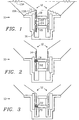
- FIG. 1 is a cross-section representing a dual voice coil loudspeaker 10 with the cone/voice coil assembly 12 at its quiescent center position, where it is seen that voice coils 14 and 16 each have a portion located in a corresponding one of magnetic gaps 18 and 20, polarized as indicated by N and S, and each of these portions is acted upon over the full length of the magnetic gap. While voice coils 14 and 16 each may be offset, as shown, relative to the corresponding magnetic gaps 18 and 20, the two offsets tend to cancel each other so that the coils 14 and 16 function in a complementary manner that provides a large excursion of travel over which the drive force and damping remain relatively constant.
- a short-circuited braking coil 22 having one or more turns is located midway between voice coils 12 and 14, affixed to the voice coil form 24.
- FIG. 2 shows the loudspeaker 10 of FIG. 1 with the voice coil assembly 12 displaced in a first direction (upwardly, as shown) and approaching the limit of the travel range.
- Inductive braking/damping is invoked by braking coil 22 moving into magnetized air gap 18 indicated by dashed flux lines.
- the movement of braking coil 22 relative to the magnetic field induces a current in braking coil 22, and counter-EMF exerts a braking/damping force on the voice coil assembly 12 via braking coil 22, acting to decrease the velocity of (upward) travel and thus limit the excursion smoothly as opposed to abrupt bottoming due to mechanical striking or reaching the limit of the suspension compliance that could occur otherwise.
- FIG. 3 shows the loudspeaker 10 of FIGs. 1 with the voice coil assembly 12, displaced in a second direction (downwardly, as shown), with braking coil 22 moving into magnetized gap 20 and thus invoking the inductive braking/damping action in the same manner as described above in connection with FIG. 2.
- the present invention provides symmetrical braking/damping in a dual voice coil loudspeaker 10 in combination with a single short-circuited braking coil 22.
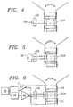
- FIG. 4 shows a diaphragm/voice coil assembly 12A of a loudspeaker as in the previous figures but with the ends of the braking coil 22A brought out to a terminal board 26, shown with a jumper 28 connected across the terminals, effectively short-circuiting the braking coil 22A and thus enabling it to function in the same manner as the directly short-circuited braking coil 22 described above in connection with FIGs. 1-3.
- FIG. 5 shows the diaphragm/voice coil assembly 12A as in FIG. 4 but with the terminals of board 26 connected to a capacitor 30 as an example of a reactive component or network of components that can be thus connected in a circuit loop including the braking coil 22A in order to introduce a frequency-dependent modification to the basic braking effect.
- FIG. 6 shows an actively-enhanced inductive braking system in which the diaphragm/voice coil assembly 12A is configured as in FIG. 4 except that the terminals of board 26 are connected to a feedback driver 32.
- a main amplifier/driver 34 driving the dual voice coils 16 and 18, receives input from an audio source 36.
- Feedback driver is preceded by a special processor 38 which may receive input from audio source 36 an shown or alternatively the input could be obtained at any of several signal nodes in the main amplifier signal path through amplifier/driver 34.
- the frequency and amplitude response of processor 38 can be flexibly modified to provide a feedback current in braking coil 22A that co-operates with induced current in a manner to augment and enhance the braking action in a desired manner.
- the invention could be practiced with the magnetic polarities N and S reversed compared to those shown.
Landscapes
- Physics & Mathematics (AREA)
- Engineering & Computer Science (AREA)
- Acoustics & Sound (AREA)
- Signal Processing (AREA)
- Audible-Bandwidth Dynamoelectric Transducers Other Than Pickups (AREA)
Abstract
Description
Claims (8)
- A bidirectional inductive braking system in a dual voice coil electro-magnetic audio loudspeaker having dual voice coils in a vibrating voice coil/diaphragm assembly, comprising:a frame of said loudspeaker;a vibratable diaphragm assembly having a cylindrical voice coil form;suspension means for mounting said diaphragm assembly to said framea first voice coil affixed to the voice coil form disposed within a first magnetic field that traverses a first annular gapa second voice coil, affixed to the voice coil form spaced from the first voice coil by a voice coil spacing dimension, disposed within a second magnetic field that traverses a second annular gap spaced from the first annular gap by a gap spacing dimension; anda short-circuited braking coil comprising at least one turn located on the voice coil form substantially midway between said first voice coil and said second voice coil;the voice coils and the magnetic fields being relatively dimensioned and arranged to cause said braking coil, (a) upon approaching a first limit of working displacement, to enter the first magnetic field and thus exert a braking force on the voice coil/diaphragm assembly, and (b) upon approaching a second limit of working displacement opposite the first limit thereof, to enter the second magnetic field and thus exert a braking force on the voice coil/diaphragm assembly; thus said braking coil is enabled to bilaterally constrain excursions of the voice coil/diaphragm assembly.
- An improvement providing inductive braking in a dual voice coil electro-magnetic audio loudspeaker of a type having first and second voice coils on a vibrating cylindrical voice coil form attached to of vibratable diaphragm assembly vibratably mounted to a frame of the loudspeaker by suspension means and disposed within first and second magnetic fields in first and second gap regions between corresponding permanent magnet poles, the improvement comprising:a short-circuited braking coil affixed to the voice coil form substantially midway between said first voice coil and said second voice coil and disposed coaxially therewith;the voice coils and the magnetic fields being relatively dimensioned and arranged to cause said braking coil, (a) upon approaching a first limit of working displacement, to enter the first magnetic field and thus exert a braking force on the voice coil, and (b) upon approaching a second limit of working displacement opposite the first limit thereof, to enter the second magnetic field and thus exert a braking force on the voice coil form and thus;
whereby said braking coil is enabled to bilaterally constrain travel of the voice coil assembly at the two opposite limits of displacement. - The improvement providing inductive braking in a dual voice coil electro magnetic audio loudspeaker as defined in claim 2 wherein said short-circuited braking coil comprises a single turn configured as a ring.
- The improvement providing inductive braking in a dual voice coil electro magnetic audio loudspeaker as defined in claim 2 wherein said short-circuited braking coil comprises a multi-turn coil having two wire ends connected together so as to short-circuit said braking coil.
- A bidirectional inductive braking system in a dual voice coil electro-magnetic audio loudspeaker having dual voice coils in a vibrating voice coil/diaphragm assembly driven from an audio source, said braking system comprising:a frame of said loudspeaker;a vibratable diaphragm assembly having a cylindrical voice coil form;suspension means for mounting said diaphragm assembly to said framea first voice coil affixed to the voice coil form disposed within a first magnetic field that traverses a first annular gapa second voice coil, affixed to the voice coil form spaced from the first voice coil by a voice coil spacing dimension, disposed within a second magnetic field that traverses a second annular gap spaced from the first annular gap by a gap spacing dimension; anda braking coil comprising at least one turn located on the voice coil form substantially midway between said first voice coil and said second voice coil, said braking coil being configured and arranged to have two electrical nodes each corresponding to an end thereof;a pair of terminals, connected respectively to the two nodes of said braking coil;braking coil enabling means having two nodes connected to said pair of terminals so as to form a loop circuit including said braking coil and said braking coil enabling means;the voice coils and the magnetic fields being relatively dimensioned and arranged to cause said braking coil, (a) upon approaching a first limit of working displacement, to enter the first magnetic field and thus exert a braking force on the voice coil/diaphragm assembly, and (b) upon approaching a second limit of working displacement opposite the first limit thereof, to enter the second magnetic field and thus exert a braking force on the voice coil/diaphragm assembly; thus said braking coil is enabled to bilaterally constrain excursions of the voice coil/diaphragm assembly.
- The bidirectional inductive braking system as defined in claim 5 wherein said braking coil enabling means comprises a conductive jumper connected across said pair of terminals so as to short-circuit said braking coil.
- The bidirectional inductive braking system as defined in claim 5 wherein said braking coil enabling means comprises at least one passive reactive electronic component in a network connected across said pair of terminals so as to influence induced current in the loop in a manner to implement a predetermined frequency-dependent braking/damping characteristic.
- The bidirectional inductive braking system as defined in claim 5 wherein said braking coil enabling means comprises a feedback driver, connected across said pair of terminals, configured and arranged to apply thereto an active feedback signal, derived in a predetermined relationship from the audio source, so as to interact with induced current in the braking coil in a predetermined manner to enhance braking/damping action of said braking coil.
Applications Claiming Priority (2)
| Application Number | Priority Date | Filing Date | Title |
|---|---|---|---|
| US934642 | 1986-11-25 | ||
| US08/934,642 US5828767A (en) | 1997-09-22 | 1997-09-22 | Inductive braking in a dual coil speaker driver unit |
Publications (3)
| Publication Number | Publication Date |
|---|---|
| EP0903961A2 true EP0903961A2 (en) | 1999-03-24 |
| EP0903961A3 EP0903961A3 (en) | 2006-10-18 |
| EP0903961B1 EP0903961B1 (en) | 2008-11-26 |
Family
ID=25465850
Family Applications (1)
| Application Number | Title | Priority Date | Filing Date |
|---|---|---|---|
| EP98203163A Expired - Lifetime EP0903961B1 (en) | 1997-09-22 | 1998-09-21 | Inductive braking in a dual coil speaker driver unit |
Country Status (6)
| Country | Link |
|---|---|
| US (1) | US5828767A (en) |
| EP (1) | EP0903961B1 (en) |
| JP (1) | JP3133729B2 (en) |
| CA (1) | CA2248433C (en) |
| DE (1) | DE69840252D1 (en) |
| ES (1) | ES2318864T3 (en) |
Cited By (1)
| Publication number | Priority date | Publication date | Assignee | Title |
|---|---|---|---|---|
| EP3026929A1 (en) * | 2014-11-27 | 2016-06-01 | BlackBerry Limited | Voice coil protection using damping |
Families Citing this family (40)
| Publication number | Priority date | Publication date | Assignee | Title |
|---|---|---|---|---|
| JPH11146479A (en) * | 1997-11-11 | 1999-05-28 | Mitsubishi Electric Corp | Speaker system |
| US6768806B1 (en) * | 1998-03-19 | 2004-07-27 | Harman International Industries, Incorporated | Shorting rings in dual-coil dual-gap loudspeaker drivers |
| JP3984397B2 (en) * | 1999-09-14 | 2007-10-03 | パイオニア株式会社 | Speaker |
| AUPQ298299A0 (en) * | 1999-09-20 | 1999-10-14 | Mass Enterprises Pty Ltd | Signal control system |
| AUPQ449999A0 (en) * | 1999-12-07 | 2000-01-06 | Mass Enterprises Pty Ltd | Sound transducer |
| US6694037B1 (en) | 1999-12-10 | 2004-02-17 | Robert Steven Robinson | Spider-less loudspeaker with active restoring apparatus |
| US7050602B2 (en) * | 2000-08-14 | 2006-05-23 | Knowles Electronics Llc. | Low capacitance receiver coil |
| US6639994B1 (en) | 2000-08-16 | 2003-10-28 | Jl Audio, Inc. | Loudspeaker having adjustable motor strength |
| US6774510B1 (en) | 2000-10-25 | 2004-08-10 | Harman International Industries, Inc. | Electromagnetic motor with flux stabilization ring, saturation tips, and radiator |
| JP4098489B2 (en) * | 2001-05-01 | 2008-06-11 | 並木精密宝石株式会社 | A portable terminal equipped with an electromagnetic induction actuator |
| CA2408045A1 (en) * | 2001-10-16 | 2003-04-16 | Audio Products International Corp. | Loudspeaker with large displacement motional feedback |
| JP4385981B2 (en) * | 2005-03-30 | 2009-12-16 | オンキヨー株式会社 | Electrodynamic speaker |
| EP1999993A4 (en) * | 2006-03-06 | 2011-03-30 | Gen Innovations Inc | Positionally sequenced loudspeaker system |
| US20070297639A1 (en) * | 2006-06-21 | 2007-12-27 | Noll Michael A | Multiple magnet loudspeaker |
| US8385580B2 (en) | 2006-08-31 | 2013-02-26 | Adamson Systems Engineering Inc. | High power low frequency transducers and method of assembly |
| JP5332146B2 (en) * | 2007-07-26 | 2013-11-06 | ヤマハ株式会社 | Speaker device |
| JP5034845B2 (en) * | 2007-10-02 | 2012-09-26 | ヤマハ株式会社 | Speaker unit and speaker device |
| JP2009194467A (en) * | 2008-02-12 | 2009-08-27 | Victor Co Of Japan Ltd | Voice coil and speaker |
| FR2961053B1 (en) * | 2010-06-04 | 2013-04-12 | Focal Jmlab | ACOUSTIC SPEAKER |
| CN102378083A (en) * | 2010-08-12 | 2012-03-14 | 郭建文 | Dynamic damping middle/low-sound loudspeaker |
| JP2014504108A (en) * | 2010-12-23 | 2014-02-13 | ニーデルマン,ポール | Thin speaker |
| US8781150B2 (en) | 2011-02-14 | 2014-07-15 | Robert Bosch Gmbh | Multiple magnetic air gap motor |
| US9571926B2 (en) * | 2011-04-08 | 2017-02-14 | Christopher Technology (Shanghai) Limited | High-efficiency low-voltage-power-supply high-power-output audio driver architecture |
| GB2499026B (en) * | 2012-02-03 | 2014-05-28 | Canon Kk | A loudspeaker driver with sensing coils for sensing the position and velocity of a voice-coil |
| US8855356B1 (en) | 2012-12-18 | 2014-10-07 | Skullcandy, Inc. | Dual ring magnet apparatus |
| US9838794B2 (en) * | 2013-04-26 | 2017-12-05 | Sound Solutions International Co., Ltd. | Double coil speaker |
| US9173035B2 (en) | 2013-11-07 | 2015-10-27 | Harman International Industries, Incorporated | Dual coil moving magnet transducer |
| US9445201B2 (en) * | 2013-11-21 | 2016-09-13 | Harman International Industries, Inc. | Inverted dual coil transducer |
| US9872109B2 (en) | 2014-12-17 | 2018-01-16 | Knowles Electronics, Llc | Shared coil receiver |
| US9854365B2 (en) | 2016-04-15 | 2017-12-26 | Harman International Industries, Inc. | Loudspeaker motor and suspension system |
| DE102018002290A1 (en) | 2017-03-27 | 2018-09-27 | Sound Solutions International Co., Ltd. | A system and method for applying a sound signal to a multi-coil electrodynamic acoustic transducer |
| US10295011B2 (en) * | 2017-10-06 | 2019-05-21 | The Boeing Company | Systems and tuned magnetic dashpots for using inductor(s) in magnetic skyhook damper isolation |
| KR20220002951A (en) | 2019-04-11 | 2022-01-07 | 메이츠 홀딩 비.브이. | Linear motor magnet assembly and loudspeaker unit |
| GB201907610D0 (en) * | 2019-05-29 | 2019-07-10 | Pss Belgium Nv | Loudspeaker |
| US11948549B2 (en) | 2019-07-17 | 2024-04-02 | Sound Solutions International Co., Ltd. | Electromagnetic actuator for a display with improved spring arrangement and output device with said actuator |
| GB2586528B (en) * | 2019-08-23 | 2021-09-22 | Tymphany Acoustic Tech Huizhou Co Ltd | A method and system for driving a voice coil of a loudspeaker |
| US11678123B2 (en) | 2020-05-20 | 2023-06-13 | Sound Solutions International Co., Ltd. | Electromagnetic actuator for a speaker or a sound transducer with a high-strength metal connection between the voice coil and the magnet system |
| CN113727258B (en) | 2020-05-20 | 2024-01-26 | 奥音科技(镇江)有限公司 | Electrodynamic exciter, speaker, electrodynamic transducer and output device |
| US12439209B2 (en) | 2022-06-10 | 2025-10-07 | Sound Solutions International (Zhenjiang) Co., Ltd. | Speaker with improved frequency response and related electronic sound signal circuit, sound system and production method |
| JP2024080123A (en) | 2022-12-01 | 2024-06-13 | アルプスアルパイン株式会社 | Speaker |
Family Cites Families (7)
| Publication number | Priority date | Publication date | Assignee | Title |
|---|---|---|---|---|
| US3047661A (en) * | 1957-01-18 | 1962-07-31 | Daniel E Winker | High fidelity audio system |
| JPS5476132A (en) * | 1977-11-30 | 1979-06-18 | Hitachi Ltd | Electro-dynamic type speaker |
| DE4041858A1 (en) * | 1990-12-24 | 1992-07-02 | Nokia Unterhaltungselektronik | DRIVE SYSTEM FOR LONG-HUBBED LOW SPEAKER |
| DE4317775C2 (en) * | 1993-02-03 | 1995-02-02 | Foster Electric Co Ltd | speaker |
| JPH0715794A (en) * | 1993-06-21 | 1995-01-17 | Matsushita Electric Ind Co Ltd | Speaker |
| JP3161677B2 (en) * | 1995-02-17 | 2001-04-25 | アルパイン株式会社 | Speaker |
| JP2002283585A (en) * | 2001-03-26 | 2002-10-03 | Fuji Xerox Co Ltd | Ink-jet recording head |
-
1997
- 1997-09-22 US US08/934,642 patent/US5828767A/en not_active Expired - Lifetime
-
1998
- 1998-09-21 EP EP98203163A patent/EP0903961B1/en not_active Expired - Lifetime
- 1998-09-21 DE DE69840252T patent/DE69840252D1/en not_active Expired - Lifetime
- 1998-09-21 ES ES98203163T patent/ES2318864T3/en not_active Expired - Lifetime
- 1998-09-22 JP JP10268052A patent/JP3133729B2/en not_active Expired - Fee Related
- 1998-09-22 CA CA002248433A patent/CA2248433C/en not_active Expired - Fee Related
Cited By (2)
| Publication number | Priority date | Publication date | Assignee | Title |
|---|---|---|---|---|
| EP3026929A1 (en) * | 2014-11-27 | 2016-06-01 | BlackBerry Limited | Voice coil protection using damping |
| US9374052B1 (en) | 2014-11-27 | 2016-06-21 | Blackberry Limited | Voice coil protection using damping |
Also Published As
| Publication number | Publication date |
|---|---|
| EP0903961A3 (en) | 2006-10-18 |
| US5828767A (en) | 1998-10-27 |
| JPH11164394A (en) | 1999-06-18 |
| ES2318864T3 (en) | 2009-05-01 |
| CA2248433C (en) | 2000-05-09 |
| EP0903961B1 (en) | 2008-11-26 |
| DE69840252D1 (en) | 2009-01-08 |
| CA2248433A1 (en) | 1999-03-22 |
| JP3133729B2 (en) | 2001-02-13 |
Similar Documents
| Publication | Publication Date | Title |
|---|---|---|
| CA2248433C (en) | Inductive braking in a dual coil speaker driver unit | |
| US4550430A (en) | Sound reproducing system utilizing motional feedback and an improved integrated magnetic structure | |
| US4256923A (en) | Sound reproducing system utilizing motional feedback and integrated magnetic structure | |
| US4598178A (en) | Means for critically damping a dynamic loudspeaker | |
| JP3514619B2 (en) | Speaker device | |
| JP2001086589A (en) | Loudspeaker | |
| US7873180B2 (en) | Voice coil actuator | |
| EP0409429A2 (en) | Loudspeaker drive unit | |
| JP3365958B2 (en) | Speaker | |
| KR19990041872A (en) | Speaker structure with double voice coil | |
| JPH067711B2 (en) | Speaker | |
| US2494918A (en) | Inductively energized electro-dynamic loud-speaker | |
| WO1999030533A1 (en) | Electrodynamic acoustic transducer with reduced equivalent inductance of the moving parts | |
| GB2473921A (en) | Compensation of rising frequency response in passive current-driven loudspeakers | |
| JP3128022B2 (en) | Coaxial speaker | |
| JP3991792B2 (en) | Speaker | |
| JPH0424715Y2 (en) | ||
| JPH04364000A (en) | Dynamic speaker | |
| KR100507700B1 (en) | Speaker having double magnetism circuit structure | |
| JP3052477B2 (en) | Speaker | |
| JP2546339Y2 (en) | Speaker | |
| JP2004350317A (en) | Speaker | |
| KR200196826Y1 (en) | Cone speaker structure | |
| JPS6219033Y2 (en) | ||
| Watkins | Circumventing Efficiency and Bass Extension Limitations |
Legal Events
| Date | Code | Title | Description |
|---|---|---|---|
| PUAI | Public reference made under article 153(3) epc to a published international application that has entered the european phase |
Free format text: ORIGINAL CODE: 0009012 |
|
| AK | Designated contracting states |
Kind code of ref document: A2 Designated state(s): AT BE CH CY DE DK ES FI FR GB GR IE IT LI LU MC NL PT SE |
|
| AX | Request for extension of the european patent |
Free format text: AL;LT;LV;MK;RO;SI |
|
| PUAL | Search report despatched |
Free format text: ORIGINAL CODE: 0009013 |
|
| AK | Designated contracting states |
Kind code of ref document: A3 Designated state(s): AT BE CH CY DE DK ES FI FR GB GR IE IT LI LU MC NL PT SE |
|
| AX | Request for extension of the european patent |
Extension state: AL LT LV MK RO SI |
|
| 17P | Request for examination filed |
Effective date: 20070330 |
|
| AKX | Designation fees paid |
Designated state(s): DE ES GB IT |
|
| 17Q | First examination report despatched |
Effective date: 20070704 |
|
| GRAP | Despatch of communication of intention to grant a patent |
Free format text: ORIGINAL CODE: EPIDOSNIGR1 |
|
| GRAS | Grant fee paid |
Free format text: ORIGINAL CODE: EPIDOSNIGR3 |
|
| GRAA | (expected) grant |
Free format text: ORIGINAL CODE: 0009210 |
|
| AK | Designated contracting states |
Kind code of ref document: B1 Designated state(s): DE ES GB IT |
|
| REG | Reference to a national code |
Ref country code: GB Ref legal event code: FG4D |
|
| REF | Corresponds to: |
Ref document number: 69840252 Country of ref document: DE Date of ref document: 20090108 Kind code of ref document: P |
|
| REG | Reference to a national code |
Ref country code: ES Ref legal event code: FG2A Ref document number: 2318864 Country of ref document: ES Kind code of ref document: T3 |
|
| PLBE | No opposition filed within time limit |
Free format text: ORIGINAL CODE: 0009261 |
|
| STAA | Information on the status of an ep patent application or granted ep patent |
Free format text: STATUS: NO OPPOSITION FILED WITHIN TIME LIMIT |
|
| 26N | No opposition filed |
Effective date: 20090827 |
|
| PG25 | Lapsed in a contracting state [announced via postgrant information from national office to epo] |
Ref country code: IT Free format text: LAPSE BECAUSE OF NON-PAYMENT OF DUE FEES Effective date: 20090921 |
|
| PGFP | Annual fee paid to national office [announced via postgrant information from national office to epo] |
Ref country code: DE Payment date: 20130927 Year of fee payment: 16 Ref country code: ES Payment date: 20130926 Year of fee payment: 16 |
|
| REG | Reference to a national code |
Ref country code: DE Ref legal event code: R119 Ref document number: 69840252 Country of ref document: DE |
|
| PG25 | Lapsed in a contracting state [announced via postgrant information from national office to epo] |
Ref country code: DE Free format text: LAPSE BECAUSE OF NON-PAYMENT OF DUE FEES Effective date: 20150401 |
|
| REG | Reference to a national code |
Ref country code: ES Ref legal event code: FD2A Effective date: 20151027 |
|
| PG25 | Lapsed in a contracting state [announced via postgrant information from national office to epo] |
Ref country code: ES Free format text: LAPSE BECAUSE OF NON-PAYMENT OF DUE FEES Effective date: 20140922 |
|
| PGFP | Annual fee paid to national office [announced via postgrant information from national office to epo] |
Ref country code: GB Payment date: 20170821 Year of fee payment: 20 |
|
| REG | Reference to a national code |
Ref country code: GB Ref legal event code: PE20 Expiry date: 20180920 |
|
| PG25 | Lapsed in a contracting state [announced via postgrant information from national office to epo] |
Ref country code: GB Free format text: LAPSE BECAUSE OF EXPIRATION OF PROTECTION Effective date: 20180920 |