KR20220002951A - Linear motor magnet assembly and loudspeaker unit - Google Patents
Linear motor magnet assembly and loudspeaker unit Download PDFInfo
- Publication number
- KR20220002951A KR20220002951A KR1020217036770A KR20217036770A KR20220002951A KR 20220002951 A KR20220002951 A KR 20220002951A KR 1020217036770 A KR1020217036770 A KR 1020217036770A KR 20217036770 A KR20217036770 A KR 20217036770A KR 20220002951 A KR20220002951 A KR 20220002951A
- Authority
- KR
- South Korea
- Prior art keywords
- linear motor
- magnet assembly
- motor magnet
- auxiliary
- magnetic element
- Prior art date
Links
- 239000012528 membrane Substances 0.000 claims abstract description 53
- 239000000725 suspension Substances 0.000 claims description 13
- 239000000696 magnetic material Substances 0.000 claims description 5
- 230000006835 compression Effects 0.000 description 5
- 238000007906 compression Methods 0.000 description 5
- 230000003068 static effect Effects 0.000 description 5
- 230000000712 assembly Effects 0.000 description 4
- 238000000429 assembly Methods 0.000 description 4
- 230000005520 electrodynamics Effects 0.000 description 3
- 239000000463 material Substances 0.000 description 3
- 230000000694 effects Effects 0.000 description 2
- 230000003321 amplification Effects 0.000 description 1
- 238000006243 chemical reaction Methods 0.000 description 1
- 230000008878 coupling Effects 0.000 description 1
- 238000010168 coupling process Methods 0.000 description 1
- 238000005859 coupling reaction Methods 0.000 description 1
- 230000003247 decreasing effect Effects 0.000 description 1
- 230000001419 dependent effect Effects 0.000 description 1
- 239000012530 fluid Substances 0.000 description 1
- 238000005339 levitation Methods 0.000 description 1
- 230000005415 magnetization Effects 0.000 description 1
- 238000004519 manufacturing process Methods 0.000 description 1
- 230000004048 modification Effects 0.000 description 1
- 238000012986 modification Methods 0.000 description 1
- 238000003199 nucleic acid amplification method Methods 0.000 description 1
Images

Classifications
-
- H—ELECTRICITY
- H04—ELECTRIC COMMUNICATION TECHNIQUE
- H04R—LOUDSPEAKERS, MICROPHONES, GRAMOPHONE PICK-UPS OR LIKE ACOUSTIC ELECTROMECHANICAL TRANSDUCERS; DEAF-AID SETS; PUBLIC ADDRESS SYSTEMS
- H04R9/00—Transducers of moving-coil, moving-strip, or moving-wire type
- H04R9/06—Loudspeakers
- H04R9/063—Loudspeakers using a plurality of acoustic drivers
-
- H—ELECTRICITY
- H04—ELECTRIC COMMUNICATION TECHNIQUE
- H04R—LOUDSPEAKERS, MICROPHONES, GRAMOPHONE PICK-UPS OR LIKE ACOUSTIC ELECTROMECHANICAL TRANSDUCERS; DEAF-AID SETS; PUBLIC ADDRESS SYSTEMS
- H04R3/00—Circuits for transducers, loudspeakers or microphones
- H04R3/002—Damping circuit arrangements for transducers, e.g. motional feedback circuits
-
- H—ELECTRICITY
- H04—ELECTRIC COMMUNICATION TECHNIQUE
- H04R—LOUDSPEAKERS, MICROPHONES, GRAMOPHONE PICK-UPS OR LIKE ACOUSTIC ELECTROMECHANICAL TRANSDUCERS; DEAF-AID SETS; PUBLIC ADDRESS SYSTEMS
- H04R7/00—Diaphragms for electromechanical transducers; Cones
- H04R7/02—Diaphragms for electromechanical transducers; Cones characterised by the construction
- H04R7/04—Plane diaphragms
-
- H—ELECTRICITY
- H04—ELECTRIC COMMUNICATION TECHNIQUE
- H04R—LOUDSPEAKERS, MICROPHONES, GRAMOPHONE PICK-UPS OR LIKE ACOUSTIC ELECTROMECHANICAL TRANSDUCERS; DEAF-AID SETS; PUBLIC ADDRESS SYSTEMS
- H04R7/00—Diaphragms for electromechanical transducers; Cones
- H04R7/16—Mounting or tensioning of diaphragms or cones
-
- H—ELECTRICITY
- H04—ELECTRIC COMMUNICATION TECHNIQUE
- H04R—LOUDSPEAKERS, MICROPHONES, GRAMOPHONE PICK-UPS OR LIKE ACOUSTIC ELECTROMECHANICAL TRANSDUCERS; DEAF-AID SETS; PUBLIC ADDRESS SYSTEMS
- H04R9/00—Transducers of moving-coil, moving-strip, or moving-wire type
- H04R9/02—Details
- H04R9/025—Magnetic circuit
-
- H—ELECTRICITY
- H04—ELECTRIC COMMUNICATION TECHNIQUE
- H04R—LOUDSPEAKERS, MICROPHONES, GRAMOPHONE PICK-UPS OR LIKE ACOUSTIC ELECTROMECHANICAL TRANSDUCERS; DEAF-AID SETS; PUBLIC ADDRESS SYSTEMS
- H04R9/00—Transducers of moving-coil, moving-strip, or moving-wire type
- H04R9/06—Loudspeakers
-
- H—ELECTRICITY
- H04—ELECTRIC COMMUNICATION TECHNIQUE
- H04R—LOUDSPEAKERS, MICROPHONES, GRAMOPHONE PICK-UPS OR LIKE ACOUSTIC ELECTROMECHANICAL TRANSDUCERS; DEAF-AID SETS; PUBLIC ADDRESS SYSTEMS
- H04R2209/00—Details of transducers of the moving-coil, moving-strip, or moving-wire type covered by H04R9/00 but not provided for in any of its subgroups
- H04R2209/026—Transducers having separately controllable opposing diaphragms, e.g. for ring-tone and voice
-
- H—ELECTRICITY
- H04—ELECTRIC COMMUNICATION TECHNIQUE
- H04R—LOUDSPEAKERS, MICROPHONES, GRAMOPHONE PICK-UPS OR LIKE ACOUSTIC ELECTROMECHANICAL TRANSDUCERS; DEAF-AID SETS; PUBLIC ADDRESS SYSTEMS
- H04R2209/00—Details of transducers of the moving-coil, moving-strip, or moving-wire type covered by H04R9/00 but not provided for in any of its subgroups
- H04R2209/041—Voice coil arrangements comprising more than one voice coil unit on the same bobbin
Landscapes
- Engineering & Computer Science (AREA)
- Physics & Mathematics (AREA)
- Acoustics & Sound (AREA)
- Signal Processing (AREA)
- Multimedia (AREA)
- Reciprocating, Oscillating Or Vibrating Motors (AREA)
- Audible-Bandwidth Dynamoelectric Transducers Other Than Pickups (AREA)
Abstract
고정된 베이스 액추에이터 구성요소(4) 및 멤브레인 작동 요소(5)를 갖는, 라우드스피커 유닛(1)에 사용하기 위한 선형 모터 자석 조립체(2)로서, 상기 멤브레인 작동 요소(5)는 선형 편위 축(A)을 갖는다. 제1 보조 자기 요소(7) 및 제2 보조 자기 요소(8)가 존재하며, 제1 보조 자기 요소(7)는 선형 편위 축(A)과 정렬된 주 축을 갖는 제1 보조 공간 자기장을 제공한다. 제2 보조 자기 요소(8)는 선형 모터 자석 조립체(2)의 멤브레인 작동 요소(5)에 고정식으로 연결되고, 제2 보조 공간 자기장을 가지며, 제2 보조 자기장은 제1 보조 공간 자기장과 중첩하고 선형 모터 자석 조립체(2)의 제1 사전결정된 편위 범위(E1)에 걸쳐 제1 보조 공간 자기장과 실질적으로 유사하게 배향된다.A linear motor magnet assembly (2) for use in a loudspeaker unit (1) having a fixed base actuator component (4) and a membrane actuating element (5), said membrane actuating element (5) having a linear excursion axis ( A) has A first auxiliary magnetic element 7 and a second auxiliary magnetic element 8 are present, the first auxiliary magnetic element 7 providing a first auxiliary spatial magnetic field having a major axis aligned with the linear excursion axis A . The second auxiliary magnetic element 8 is fixedly connected to the membrane actuating element 5 of the linear motor magnet assembly 2 and has a second auxiliary spatial magnetic field, the second auxiliary magnetic field overlapping the first auxiliary spatial magnetic field and It is oriented substantially similar to the first auxiliary spatial magnetic field over the first predetermined excursion range E1 of the linear motor magnet assembly 2 .
Description
본 발명은 라우드스피커 유닛에 사용하기 위한 선형 모터 자석 조립체로서, 상기 선형 모터 자석 조립체는 고정된 베이스 액추에이터 구성요소 및 멤브레인 작동 요소를 포함하며, 상기 멤브레인 작동 요소는 선형 편위 축을 갖는, 선형 모터 자석 조립체에 관한 것이다.SUMMARY OF THE INVENTION The present invention is a linear motor magnet assembly for use in a loudspeaker unit, the linear motor magnet assembly comprising a fixed base actuator component and a membrane actuating element, the membrane actuating element having a linear axis of excursion. is about
이러한 선형 모터 자석 조립체는, 예를 들어 멤브레인 및 멤브레인을 구동하는 복수의 구동 유닛을 포함하는 라우드스피커 유닛을 개시하는 국제특허공개 WO2018/057814호에 공지되어 있다.Such a linear motor magnet assembly is known, for example, from WO2018/057814, which discloses a loudspeaker unit comprising a membrane and a plurality of drive units for driving the membrane.
본 발명은 선형 모터 액추에이터 시스템의 성능을 향상시킬 수 있는 라우드스피커 유닛에 사용하기 위한 선형 모터 자석 조립체를 제공하기 위한 것이다.SUMMARY OF THE INVENTION The present invention seeks to provide a linear motor magnet assembly for use in a loudspeaker unit capable of improving the performance of a linear motor actuator system.
본 발명에 따르면, 고정된 베이스 액추에이터 구성요소 및 멤브레인 작동 요소를 갖는 전술한 바와 같은 선형 모터 자석 조립체가 제공되며, 상기 멤브레인 작동 요소는 선형 편위 축을 갖는다. 제1 보조 자기 요소 및 제2 보조 자기 요소가 존재하며, 상기 제1 보조 자기 요소는 선형 모터 자석 조립체의 선형 편위 축과 정렬된 주 축을 갖는 제1 보조 공간 자기장을 제공한다. 상기 제2 보조 자기 요소는 선형 모터 자석 조립체의 멤브레인 작동 요소에 고정식으로 연결되고, 제2 보조 공간 자기장을 가지며, 상기 제2 보조 공간 자기장은 상기 제1 보조 공간 자기장과 중첩하고 상기 선형 모터 자석 조립체의 제1 사전결정된 편위 범위에 걸쳐 상기 제1 보조 공간 자기장과 실질적으로 유사하게 배향된다.According to the present invention, there is provided a linear motor magnet assembly as described above having a fixed base actuator component and a membrane actuating element, the membrane actuating element having a linear excursion axis. A first auxiliary magnetic element and a second auxiliary magnetic element are present, the first auxiliary magnetic element providing a first auxiliary spatial magnetic field having a major axis aligned with the linear excursion axis of the linear motor magnet assembly. the second auxiliary magnetic element is fixedly connected to the membrane actuating element of the linear motor magnet assembly and has a second auxiliary spatial magnetic field, the second auxiliary spatial magnetic field overlapping the first auxiliary spatial magnetic field and the linear motor magnet assembly oriented substantially similar to the first auxiliary spatial magnetic field over a first predetermined range of excursions of
상기 제1 보조 자기 요소 및 상기 제2 보조 자기 요소는, 상기 선형 모터 자석 조립체가 이동할 때 제1 보조 자기 요소 및 제2 보조 자기 요소에 의해 발생된 결합력이 모터 이동을 증폭하도록 위치된다. 따라서, 본 발명은 선형 모터의 편위(excursion)에 대한 강성(stiffness)을 감소시킴으로써 에너지 효율적이고 개선된 선형 이동 시스템을 제공한다. 이는 선형 모터 시스템에 의해 요구되는 전력을 효과적으로 감소시켜 완전한 편위를 만든다. 추가적인 실시예들은 종속 청구항들에 의해 기술되며, 도면들에 도시된 예시적인 실시예들을 참조하여 설명된다.The first auxiliary magnetic element and the second auxiliary magnetic element are positioned such that the coupling force generated by the first auxiliary magnetic element and the second auxiliary magnetic element amplifies the motor movement as the linear motor magnet assembly moves. Accordingly, the present invention provides an energy efficient and improved linear motion system by reducing the stiffness to excursion of a linear motor. This effectively reduces the power required by the linear motor system, creating a complete excursion. Further embodiments are described by the dependent claims and are explained with reference to the exemplary embodiments shown in the drawings.
이하, 첨부된 도면을 참조하여 본 발명을 보다 상세히 설명한다.
도 1a 및 1b는 본 발명의 선형 자석 모터 조립체의 제1 실시예에 따른 2가지의 작동 상황에서의 영구 자석 보조 구조체의 일 예를 도시한다.
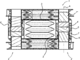
도 2a는 또 다른 실시예에 따른 2개의 선형 모터 자석 조립체에 의해 각각 구동되는 2개의 대향 멤브레인을 갖는 라우드스피커 유닛의 사시도를 도시한다.
도 3은 본 발명의 다른 실시예에 따른 선형 모터 자석 조립체의 단면도를 도시한다.Hereinafter, the present invention will be described in more detail with reference to the accompanying drawings.
1A and 1B show an example of a permanent magnet auxiliary structure in two operating situations according to a first embodiment of a linear magnet motor assembly of the present invention.
2A shows a perspective view of a loudspeaker unit having two opposing membranes each driven by two linear motor magnet assemblies according to another embodiment;
3 shows a cross-sectional view of a linear motor magnet assembly according to another embodiment of the present invention.
본 발명은 선형 모터 액추에이터에 의해 발생된 운동을 돕고 증폭하기 위해 자기장을 사용하는 영구 자석의 조합을 포함하며, 선형 모터 및 영구 자석 보조 장치의 조합을 사용하여 전체 라우드스피커 장치의 강성에서 비선형성에 대응하는 특징의 적용을 포함하는 선형 모터 자석 조립체(본 명세서에서 액추에이터 증폭 장치 또는 영구 자석 보조기로도 나타냄)에 관한 것이다.The present invention includes a combination of permanent magnets that use a magnetic field to aid and amplify the motion generated by a linear motor actuator, using a combination of a linear motor and a permanent magnet assist to counter non-linearities in stiffness of the overall loudspeaker device A linear motor magnet assembly (also referred to herein as an actuator amplifying device or permanent magnet assist) comprising the application of the following features.
본 발명은 특허공개공보 WO2018/0596814호, 및 동일한 출원인으로부터의 비공개된 PCT/NL2018/050263호, PCT/EP2018/0779509호, PCT/EP2019/055831호 및 EP19162460.0호에 기술 및 개시된 예와 같은 다양한 형태의 라우드스피커 유닛(1)에 적용될 수 있다. 선형 모터 자석 조립체(2)는 본 명세서에 기술된 예시적인 실시예들 중 임의의 실시예에 따라 구현될 수 있다.The present invention is described and disclosed in Patent Publication Nos. WO2018/0596814, and unpublished PCT/NL2018/050263, PCT/EP2018/0779509, PCT/EP2019/055831 and EP19162460.0 from the same applicant. It can be applied to the
전기역학적 트랜스듀서는 일반적으로 선형 모터, 멤브레인, 및 선형 모터의 서스펜션을 갖는다. 중간 및 저주파수 응답을 위한 트랜스듀서는 일반적으로 인클로저에 장착된다. (예를 들어, 밀봉 또는 포트될 수 있는) 인클로저에 트랜스듀서를 장착하는 것은 선형 모터에 의해 극복될 필요가 있는 서스펜션의 총 강성을 증가시킨다. 밀봉형 또는 포트형 인클로저에서 저주파수 응답(10Hz - 200Hz)을 제공할 수 있는 전기역학적 트랜스듀서 시스템은 일반적으로 트랜스듀서의 자체 서스펜션으로부터 발생하는 강성뿐만 아니라 인클로저 내부의 공기 압축으로부터 발생하는 강성을 가질 것이다. 멤브레인이 공기를 압축할 필요가 있을 때 공기 압축 유도 강성도(air compression induced stiffness)가 증가하는데, 필요한 압축이 더 높을수록, 강성이 더 높아진다. 트랜스듀서의 자기 서스펜션 강성은 공기 유도 강성도가 증가함에 따라 증가될 필요가 있을 것이고, 공기 유도 강성에 의해 야기되는 서스펜션의 원하지 않는 변형을 방지한다. 결과적으로, 선형 모터 액추에이터는 원하는 공기 압축을 생성하기 위해 증가된 전력 입력을 필요로 할 것이다. 이상적으로, 밀봉형 또는 포트형 인클로저에 배치될 때 강성의 비선형성에 의해 야기되는 가장 낮은 왜곡을 갖는 전기역학적 트랜스듀서를 생성하기 위해, 인클로저로부터 발생하는 효과에 의해 야기되거나 요구되는 가장 낮은 가능한 강성 증가를 달성하려고 시도할 것이다. 트랜스듀서는 이상적으로 자유 공기인 것과 같이 거동할 것이다.Electrodynamic transducers generally have a linear motor, a membrane, and a suspension of the linear motor. Transducers for mid- and low-frequency responses are typically mounted in enclosures. Mounting the transducer in an enclosure (which may, for example, be sealed or ported) increases the total stiffness of the suspension that needs to be overcome by the linear motor. An electrodynamic transducer system capable of providing a low frequency response (10 Hz - 200 Hz) in sealed or potted enclosures will typically have stiffness resulting from compression of air inside the enclosure as well as stiffness resulting from the transducer's own suspension. . Air compression induced stiffness increases when the membrane needs to compress air, the higher the compression required, the higher the stiffness. The magnetic suspension stiffness of the transducer will need to be increased as the air-induced stiffness increases, preventing unwanted deformation of the suspension caused by the air-induced stiffness. As a result, the linear motor actuator will require increased power input to produce the desired air compression. Ideally, the lowest possible increase in stiffness caused or required by the effects arising from the enclosure to produce an electrodynamic transducer with the lowest distortion caused by the nonlinearity of stiffness when placed in a sealed or ported enclosure. will try to achieve The transducer would ideally behave as if it were free air.
본 발명은 선형 모터의 완전한 편위 범위에 걸쳐 강성을 감소시킴으로써 선형 모터 액추에이터 시스템의 성능을 개선시키기 위해 적어도 2개의 영구 자석의 조합을 사용하는 장치를 제공하여, 선형 모터 시스템에 의해 요구되는 전력을 효과적으로 감소시켜 편위 범위를 통해 이동하도록 한다.SUMMARY OF THE INVENTION The present invention provides a device that uses a combination of at least two permanent magnets to improve the performance of a linear motor actuator system by reducing the stiffness over the complete range of excursions of the linear motor, effectively reducing the power required by the linear motor system. Decrease to move through the range of excursions.
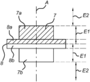
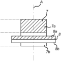
도 1a 및 도 1b는 2개의 작동 상황에서 선형 모터 자석 조립체(2) 또는 영구 자석 보조 구조체의 일부의 예를 도시한다. 이러한 예시적인 실시예는 축방향으로 자화된 자석을 포함하며, 제2 보조 자기 요소(8)는 실린더 형상의 자석인 제1 보조 자기 요소(7) 주위로 이동하는 링 형상의 자석이다.1A and 1B show examples of a portion of a linear
본 발명은 선형 모터의 편위를 만들기 위해 선형 모터 시스템에 의해 필요한 전력을 덜 필요로 하는 라우드스피커 유닛에 사용하기 위한 개선된 선형 모터 자석 조립체를 제공한다. 따라서, 본 발명은 비용 효과적이고 시스템의 구조적 변경을 덜 필요로 하는 전력 효율적인 시스템을 제공한다.SUMMARY OF THE INVENTION The present invention provides an improved linear motor magnet assembly for use in a loudspeaker unit that requires less power required by a linear motor system to produce an excursion of the linear motor. Accordingly, the present invention provides a power efficient system that is cost effective and requires less structural changes to the system.
도 2a는 단면도를 도시하고, 도 2b는 선형 모터 자석 조립체(2)에 의해 각각 구동되는 2개의 대향 멤브레인(3)을 갖는 본 발명의 예시적인 실시예의 사시도를 도시하며, 본 발명의 실시예가 구현되어 있다.2A shows a cross-sectional view, and FIG. 2B shows a perspective view of an exemplary embodiment of the present invention having two
선형 모터 자석 조립체(2)는 예를 들어 라우드스피커 유닛(1)에 사용하기 위해 적용된다. 선형 모터 자석 조립체(2)는 고정된 베이스 액추에이터 요소(4) 및 멤브레인 작동 요소(5)를 포함한다. 고정된 베이스 액추에이터 구성요소(4)는 선형 모터 자석 조립체(2)의 일부인 2개의 축방향으로 정렬된 자기 요소(7, 7*)를 기계적으로 연결하고 있다. 고정된 베이스 액추에이터 구성요소(4)의 재료는 2개의 축방향으로 정렬된 자기 요소(7, 7*)와 멤브레인 작동 요소(5) 사이의 연동을 위한 적절한 자기장 분포를 보장하는 비자성 재료이다. 멤브레인 작동 요소(5)는 이동가능하고 선형 편위 축(A), 즉 멤브레인(3)이 상하로 이동하는 방향을 갖는다. 작동시, 멤브레인 작동 요소(5)는 멤브레인(3)에 연결된 선형 모터 자기 조립체(2)를 이동시킨다. 따라서, 멤브레인(3)은 작동 방향에 따라 상하로 이동한다. 2개의 대향 멤브레인(3)은 사전결정된 거리만큼 분리된다. 선형 모터 자석 조립체(2)는 제1 보조 자기 요소(7)(2개의 축방향으로 정렬된 자기 요소들(7, 7*) 중 하나) 및 제2 보조 자기 요소(8)를 더 포함한다. 제1 보조 자기 요소(7)는 선형 모터 자석 조립체(2)의 선형 편위 축(A)과 정렬된 주 축을 갖는 제1 보조 공간 자기장을 제공한다. 제2 보조 자기 요소(8)는 선형 모터 자석 조립체(2)의 멤브레인 작동 요소(5)에 고정식으로 연결되고, 제2 보조 공간 자기장을 갖는다. 제2 보조 자기장은 제1 보조 공간 자기장과 중첩하고, 선형 모터 자석 조립체(2)의 제1 사전결정된 편위 범위(E1)를 통해 제1 보조 공간 자기장과 실질적으로 유사하게 배향된다.The linear
라우드스피커 유닛(1)의 본 발명 실시예는 라우드스피커 유닛(1)의 상부 및 하부 표면 상에 배치된 2개의 대향 멤브레인(3)을 갖는다. 라우드스피커 유닛(1)은 도 2a 및 2b에서 직사각형 유닛으로 도시되어 있지만, 이는 제한적인 기하학적 형상이 아니다. 각각의 멤브레인(3)의 베이스 요소는 멤브레인(3)의 대각선 단부 중 2개에서 2개의 선형 모터 자기 조립체(2)에 구조적으로 연결된다. 도 2b에 도시된 바와 같이, 하부 멤브레인(3)의 베이스 요소는 멤브레인의 하부 대각선 단부 모두에 위치된 2개의 상이한 선형 모터 자기 조립체(2)에 의해 구조적으로 연결된다. 유사하게, 상부 멤브레인(3)의 베이스 요소는 멤브레인의 상부 대각선 단부 모두에 위치된 2개의 상이한 선형 모터 자기 조립체들(2)에 의해 구조적으로 연결된다. 이러한 특징의 조합에 대한 효과는 제1 사전결정된 편위 범위 내의 편위 방향으로의 증가하는 자기력(또는 감소된 강성)이며, 즉 제1 및 제2 보조 자기 요소는 라우드스피커 유닛(1) 내의 서스펜션 힘 및 공기 압축력을 극복하는데 도움을 준다. 제2 보조 자기 요소(8)는 예를 들어 도 2a의 단면도에 도시된 바와 같이 홀더 바디를 사용하여 멤브레인 작동 요소(5)에 부착된다. 고정식 연결은 이러한 2개의 요소 중 서로에 대한 직접적인 물리적 부착을 반드시 암시하는 것은 아니다.The present embodiment of the
또 다른 실시예에서, 제2 보조 자기 요소(8)는 멤브레인 작동 요소(5)로부터 선형 편위 축(A)을 따라 제1 거리에 위치된다. 도 1a는 제2 보조 자기 요소(8)가 선형 편위 축(A)을 따라 제1 보조 자기 요소(7)의 중심에 위치되는 작동 상황을 도시한다. 또한, 도 1b는 제2 보조 자기 요소(8)가 선형 편위 축(A)을 따라 제1 보조 자기 요소(7)의 중심으로부터 떨어져 위치되는 작동 상황을 도시한다.In yet another embodiment, the second auxiliary
본 발명의 또 다른 실시예는 선형 모터 자석 조립체(2)에 관한 것으로, 제2 보조 공간 자기장 및 제1 보조 공간 자기장은 선형 모터 자석 조립체(2)의 제2 사전결정된 편위 범위(E2)에 걸쳐 부분적으로만 중첩된다. 이러한 특징은 제2 사전결정된 편위 범위(E2)에서 편위 방향으로 감소하는 힘을 초래할 것이다. 도 1a 및 1b의 예시적인 실시예에서, 제1 보조 자기 요소(7)는 축(A)을 따라 유한 치수를 가지며, 제2 사전결정된 편위 범위(E2)는 제1 사전결정된 편위 범위(E1)를 넘어 연장된다.Another embodiment of the present invention relates to a linear motor magnet assembly (2), wherein the second auxiliary spatial magnetic field and the first auxiliary spatial magnetic field are over a second predetermined excursion range (E2) of the linear motor magnet assembly (2). Only partially overlapped. This characteristic will result in a force decreasing in the excursion direction in the second predetermined excursion range E2 . 1a and 1b , the first auxiliary
본 발명의 또 다른 실시예에 따르면, 선형 모터 자석 조립체(2)가 제공되며, 제1 보조 자기 요소(7)는 선형 모터 자석 조립체(2)의 고정 베이스 액추에이터 요소(4)에 고정식으로 연결된다. 고정식 연결은 이들 2개의 요소 중 서로에 대한 직접 부착 또는 구조적 연결을 반드시 암시하지는 않는다. 이는 예를 들어 간단한 자기 연결 또는 공중 부양에 의한 자기 연결일 수 있다.According to another embodiment of the present invention, a linear motor magnet assembly (2) is provided, wherein a first auxiliary magnetic element (7) is fixedly connected to a fixed base actuator element (4) of the linear motor magnet assembly (2) . A rigid connection does not necessarily imply a direct attachment or structural connection of either of these two elements to each other. This may be, for example, a simple magnetic connection or a magnetic connection by levitation.
본 발명의 또 다른 실시예는 멤브레인 작동 요소(5) 및 고정 베이스 액추에이터 구성요소(4)에 연결된 서스펜션 조립체(6)를 포함하는 선형 모터 자석 조립체(2)에 관한 것으로, 서스펜션 조립체(6)는 선형 편위 축(A)을 따라 멤브레인 작동 요소(5)와 고정 베이스 액추에이터 구성요소(4) 사이의 상호 이동을 허용하고, 선형 편위 축(A)을 따라 멤브레인 작동 요소(5)(및 그에 고정식으로 연결된 제2 보조 자기 요소(8))의 휴지 위치를 형성하도록 배치된다.Another embodiment of the present invention relates to a linear motor magnet assembly (2) comprising a membrane actuating element (5) and a suspension assembly (6) connected to a fixed base actuator component (4), the suspension assembly (6) comprising: allows for mutual movement between the
본 발명은 선형 모터의 완전한 편위에 걸쳐 강성을 감소시킴으로써 선형 모터 액추에이터 시스템의 성능을 향상시키기 위해 적어도 2개의 영구 자석들의 조합을 사용하여 라우드스피커 유닛에 사용하기 위한 선형 모터 자석 조립체를 더 제공하여, 선형 모터 시스템에 의해 요구되는 전력을 효과적으로 감소시켜 완전한 편위를 만든다. 본 발명의 실시예는 또한 선형 모터 액추에이터에 의해 발생된 운동을 돕고 증폭하기 위해 자기장을 사용하는 영구 자석의 조합, 및 선형 모터 및 영구 자석 보조 장치의 조합을 사용함으로써 완전한 시스템의 강성에서 비선형성에 대응하는 특징의 적용을 포함하는 선형 모터 액추에이터 증폭 장치(또는 영구 자석 보조기)에 관한 것이다.The present invention further provides a linear motor magnet assembly for use in a loudspeaker unit using a combination of at least two permanent magnets to improve the performance of a linear motor actuator system by reducing stiffness over full excursion of the linear motor, It effectively reduces the power required by the linear motor system to create a complete excursion. Embodiments of the present invention also counteract nonlinearities in the stiffness of the complete system by using combinations of permanent magnets that use magnetic fields to assist and amplify the motion generated by linear motor actuators, and combinations of linear motors and permanent magnet aids. It relates to a linear motor actuator amplification device (or permanent magnet assist) comprising the application of the following features.
일 실시예에 따르면, 본 발명은 선형 모터 자석 조립체(2)에 관한 것으로, 제2 보조 자기 요소(8)는 영구 자성 재료를 포함한다. 본 발명의 다른 실시예는 선형 모터 자석 조립체(2)에 관한 것으로, 제2 보조 자기 요소(8)는 전자석을 포함한다. 이러한 시스템에서, 제2 보조 자기 요소(8)는 예를 들어 특정 시간 기간 동안 전기적으로 자화된다. 유사한 방식으로, 본 발명의 다른 실시예는 선형 모터 자석 조립체(2)에 관한 것으로, 제1 보조 자기 요소(7)는 영구 자성 재료를 포함한다. 본 발명의 또 다른 실시예는 선형 모터 자석 조립체(2)에 관한 것으로, 제1 보조 자기 요소(7)는 전자석을 포함한다.According to one embodiment, the present invention relates to a linear motor magnet assembly (2), wherein the second auxiliary magnetic element (8) comprises a permanent magnetic material. Another embodiment of the present invention relates to a linear motor magnet assembly (2), wherein the second auxiliary magnetic element (8) comprises an electromagnet. In such a system, the second auxiliary
본 발명의 또 다른 실시예에 따르면, 선형 모터 자석 조립체(2) 또는 모터 보조 장치가 제공되며, 보조 유닛은 적어도 2개의 영구 자석(7, 8)을 포함한다. 하나의 자석은 선형 모터 액추에이터 시스템의 정적 부분에 부착된다. 적어도 2개의 자석(7, 8) 중 다른 하나는 전술한 선형 모터 액추에이터 시스템의 고정 부분에 부착된다. 자석(7, 8)은 선형 모터 액추에이터가 이동할 때, 조합된 이동 및 정적 자석(7, 8)의 보조 자기장에 의해 발생된 힘들이 모터 이동을 증폭하도록 위치된다. 영구 자석 보조기의 아키텍처는 선형 모터 시스템의 강성에 대응하는 영구 자석 시스템의 편위에 대한 반력에서의 전체 힘 및 변화를 결정한다. 본 발명의 구조 및 상호 요소 배향은 보다 에너지 효율적인 선형 이동 시스템을 제공할 수 있게 한다.According to another embodiment of the present invention, there is provided a linear motor magnet assembly ( 2 ) or a motor auxiliary device, the auxiliary unit comprising at least two permanent magnets ( 7 , 8 ). One magnet is attached to the static part of the linear motor actuator system. The other of the at least two
예시적인 실시예는 선형 모터 액추에이터 시스템과 조합하여 사용될 수 있는 영구 자석 구조체에 관한 것이며, 영구 자석 구조체는 적어도 2개의 영구 자석 중 하나가 선형 모터 액추에이터 시스템의 이동 부분에 부착되고, 적어도 하나의 영구 자석은 선형 모터 액추에이터 시스템의 정적 부분에 부착되며, 상기 영구 자석은 영구 자석 시스템의 영구 자석의 조합된 자기장이 선형 모터 액추에이터 시스템의 편위에 대한 증가하는 강성에 대응하는 방식으로 배치된다.Exemplary embodiments are directed to a permanent magnet structure that may be used in combination with a linear motor actuator system, wherein one of at least two permanent magnets is attached to a moving portion of the linear motor actuator system, the at least one permanent magnet is attached to a static portion of the linear motor actuator system, wherein the permanent magnets are positioned in such a way that the combined magnetic field of the permanent magnets of the permanent magnet system corresponds to an increasing stiffness to excursion of the linear motor actuator system.
또 다른 실시예에서, 영구 자석 구조체 및 선형 모터 액추에이터 시스템은 선형 모터 액추에이터의 이동 부분을 정적 휴지 위치로 복귀시키는 서스펜션과 조합하여 제공되며, 상기 서스펜션은 공기 또는 유체 압력에 의해 야기되는 서스펜션 장치 또는 강성의 기계적 강성에 의해 야기된다.In yet another embodiment, a permanent magnet structure and a linear motor actuator system are provided in combination with a suspension that returns a moving portion of the linear motor actuator to a static rest position, wherein the suspension is a suspension device or stiffness caused by air or fluid pressure. caused by the mechanical stiffness of
본 발명은 또한 라우드스피커 유닛에 적용되는 영구 자석 구조체 및 선형 모터 액추에이터 시스템에 관한 것으로, 영구 자석은 라우드스피커 유닛의 멤브레인 상에 있고, 정적 자석은 멤브레인 위와 아래에 배치된다.The present invention also relates to a permanent magnet structure and a linear motor actuator system applied to a loudspeaker unit, wherein the permanent magnet is on a membrane of the loudspeaker unit, and the static magnet is disposed above and below the membrane.
본 발명의 또 다른 실시예는 선형 모터 자석 조립체(2)에 관한 것으로, 제1 보조 자기 요소(7)는 고정 베이스 액추에이터 구성요소(4)와 일체로 형성된다. 이는 선형 모터 자석 조립체가 하나 적은 구조적 요소(공유된 구성요소)를 가짐으로써, 더 적은 비용 및 더 용이한 제조를 초래한다. 제1 보조 자기 요소(7)는 영구 자석 재료 또는 전자석 재료를 포함한다.Another embodiment of the present invention relates to a linear motor magnet assembly (2), wherein a first auxiliary magnetic element (7) is integrally formed with a fixed base actuator component (4). This results in lower cost and easier manufacture as the linear motor magnet assembly has one less structural element (components shared). The first auxiliary
본 발명의 예시적인 실시예는 선형 모터 자석 조립체(2)에 관한 것으로, 제1 보조 자기 요소(7)는 (도 1a 및 1b에 도시된 예시적인 실시예에 도시된 바와 같이, 그 외측 단부에 있는 대향하는 자극(7a, 7b)을 갖는) 실린더(또는 로드) 형상의 축방향으로 자화된 영구 자석이다. 본 발명의 또 다른 실시예는 선형 모터 자석 조립체(2)에 관한 것으로, 제2 보조 자기 요소(8)는 제1 보조 자기 요소(7)의 최대 단면 직경보다 큰 중심 구멍을 갖는 축방향으로 정렬된 자극(8a, 8b)을 갖는 링 형상이다. 이러한 기하학적 형상으로, 상이한 작동 위치에서 제2 보조 자기 요소(8) 내에 제1 보조 자기 요소(7)를 배치할 수 있다.An exemplary embodiment of the present invention is directed to a linear motor magnet assembly (2), wherein a first auxiliary magnetic element (7) is provided at its outer end (as shown in the exemplary embodiment shown in FIGS. 1A and 1B ). It is an axially magnetized permanent magnet in the shape of a cylinder (or rod) with opposing
본 발명의 또 다른 실시예는 선형 모터 자석 조립체(2)에 관한 것으로, 제1 보조 자기 요소(7)는 사전결정된 형상을 가져서, 선형 모터 자석 조립체(2)의 편위 범위에 걸쳐 사전결정된 제1 보조 공간 자기장 프로파일을 제공한다. 본 발명의 또 다른 실시예는 선형 모터 자석 조립체(2)에 관한 것으로, 사전결정된 형상은 제1 보조 자기 요소(7)의 중간 부분에서 최대 직경을 갖는 이중(예컨대, 절두원추형) 원뿔 형상이다. 이는 자석 중 하나를 원뿔 형상의 자석으로서 가짐으로써 구현될 수 있으며, 그 형상은 편위에 걸쳐 변화하는 강도의 자기장을 생성한다. 이는 자기장의 변화 강도를 고려하여 제1 보조 자기 요소(7)에 대한 제2 보조 자기 요소(8)의 상대 이동을 보다 효율적으로 제어할 수 있게 한다.Another embodiment of the present invention relates to a linear motor magnet assembly (2), wherein the first auxiliary magnetic element (7) has a predetermined shape, such that a first predetermined Provides an auxiliary spatial magnetic field profile. Another embodiment of the present invention relates to a linear motor magnet assembly (2), wherein the predetermined shape is a double (eg frusto-conical) cone shape with a maximum diameter in the middle portion of the first auxiliary magnetic element (7). This can be implemented by having one of the magnets as a cone-shaped magnet, the shape of which creates a magnetic field of varying strength over the excursions. This makes it possible to more efficiently control the relative movement of the second auxiliary
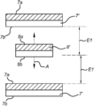
도 3은 본 발명의 다른 실시예에 따른 선형 모터 자석 조립체의 단면도를 도시하며, 제1 보조 자기 요소를 형성하는 서로 대향하는 2개의 자성체(7')를 포함하며, 그 사이에 위치된 제2 보조 자기 요소를 형성하는 자성체(8')를 갖는다. 2개의 자성체는 유사한 유형의 자화일 수 있는데, 예를 들어 양자는 영구 자석일 수 있거나 또는 양자는 전자석일 수 있다. 대안적으로, 2개의 자성체(7')는 상이한 방식으로 자화될 수 있고, 예를 들어 이들 중 하나는 영구 자석일 수 있고, 다른 하나는 전자석일 수 있다.Figure 3 shows a cross-sectional view of a linear motor magnet assembly according to another embodiment of the present invention, comprising two opposed magnetic bodies 7' forming a first auxiliary magnetic element, a second positioned therebetween; It has a magnetic body 8' forming an auxiliary magnetic element. The two magnetic bodies may be of a similar type of magnetization, for example both may be permanent magnets or both may be electromagnets. Alternatively, the two magnetic bodies 7' may be magnetized in different ways, for example one of them may be a permanent magnet and the other an electromagnet.
제1 보조 자기 요소 및 제2 보조 자기 요소의 치수 및 형상은 상이할 수 있다. 예를 들어, 제1 보조 자기 요소는 평탄 형상 또는 디스크 형상일 수 있다. 제2 보조 자기 요소는 디스크 형상 또는 링 형상일 수 있다. 또한, 제1 보조 자기 요소와 제2 보조 자기 요소의 크기는 상이할 수 있다. 전술한 바와 같이, 본 발명의 다른 실시예는 선형 모터 자석 조립체(2)에 관한 것으로, 제1 보조 자기 요소(7)는 선형 편위 축(A)을 따라 서로 사전결정된 거리에 2개(예컨대, 영구적인) 자성체(7)(예컨대, 평탄 형상 또는 디스크 형상)를 포함하고, 제2 보조 자기 요소(8)는 2개의 자성체(7')들 사이에 위치된 축방향으로 자화된 자성체(8')(예컨대, 디스크 형상 또는 링 형상)를 포함한다. 2개의 자성체(7')의 존재로 인해, 제2 보조 공간 자기장과 제1 보조 공간 자기장은 대칭 방향으로 선형 모터 자석 조립체(2)의 제2 사전결정된 편위 범위(E2)에 걸쳐 부분적으로 중첩하고 있다. 이러한 특징은 제2 의 사전결정된 편위 범위(E2)에서 편위 방향으로의 힘을 추가적으로 감소시킬 것이다.The dimensions and shapes of the first auxiliary magnetic element and the second auxiliary magnetic element may be different. For example, the first auxiliary magnetic element may be flat-shaped or disk-shaped. The second auxiliary magnetic element may be disk-shaped or ring-shaped. Also, the sizes of the first auxiliary magnetic element and the second auxiliary magnetic element may be different from each other. As mentioned above, another embodiment of the present invention relates to a linear
본 발명의 또 다른 실시예는 선형 모터 자석 조립체(2)에 관한 것으로, 선형 모터 자석 조립체(2)의 선형 편위 축(A)과 정렬된 주 축을 갖는 메인 공간 자기장을 갖는 2개의 축방향으로 정렬된 자기 요소(7, 7*)를 더 포함하고, 멤브레인 작동 요소(5)는 보이스 코일을 포함하며, 상기 보이스 코일은 선형 편위 축(A)을 따라 보이스 코일을 이동시키기 위해(즉, 멤브레인(3)을 구동하기 위해) 메인 공간 자기장과 상호 작용하는 코일 자기장을 생성하도록 배치된다.Another embodiment of the present invention relates to a linear motor magnet assembly (2), two axially aligned with a main spatial magnetic field having a major axis aligned with the linear excursion axis (A) of the linear motor magnet assembly (2). a
본 발명의 다른 실시예는 멤브레인(3), 및 선형 모터 자석 조립체(2)를 포함하는 라우드스피커 유닛(1)에 관한 것으로, 멤브레인 작동 요소(5) 및 제2 보조 자기 요소(8)는 멤브레인(3)에 고정식으로 연결된다Another embodiment of the present invention relates to a loudspeaker unit (1) comprising a membrane (3) and a linear motor magnet assembly (2), wherein the membrane actuating element (5) and the second auxiliary magnetic element (8) are membrane (3) is fixedly connected to
본 발명은 도면에 도시된 다수의 예시적인 실시예를 참조하여 상술되되었다. 일부 부분들 또는 요소들의 수정들 및 대안적인 구현들이 가능하며, 첨부된 청구항들에 정의된 바와 같은 보호 범위 내에 포함된다.The invention has been described above with reference to a number of exemplary embodiments shown in the drawings. Modifications and alternative implementations of some parts or elements are possible and are included within the scope of protection as defined in the appended claims.
Claims (17)
상기 제1 보조 자기 요소(7)는 상기 선형 모터 자석 조립체(2)의 선형 편위 축(A)과 정렬된 주 축을 갖는 제1 보조 공간 자기장을 제공하고, 상기 제2 보조 자기 요소(8)는 상기 선형 모터 자석 조립체(2)의 멤브레인 작동 요소(5)에 고정식으로 연결되고 제2 보조 공간 자기장을 갖고, 상기 제2 보조 공간 자기장은 상기 제1 보조 공간 자기장과 중첩하고 상기 선형 모터 자석 조립체(2)의 제1 사전결정된 편위 범위(E1)에 걸쳐 상기 제1 보조 공간 자기장과 실질적으로 유사하게 배향되는,
선형 모터 자석 조립체.
A linear motor magnet assembly (2) for use in a loudspeaker unit, the linear motor magnet assembly (2) comprising a fixed base actuator component (4) and a membrane actuating element (5), the membrane actuating element ( 5) has a linear excursion axis (A), said linear motor magnet assembly (2) further comprising a first auxiliary magnetic element (7) and a second auxiliary magnetic element (8) ) in
The first auxiliary magnetic element (7) provides a first auxiliary spatial magnetic field having a major axis aligned with the linear excursion axis (A) of the linear motor magnet assembly (2), and the second auxiliary magnetic element (8) is fixedly connected to the membrane actuating element (5) of the linear motor magnet assembly (2) and having a second auxiliary spatial magnetic field, the second auxiliary spatial magnetic field overlapping the first auxiliary spatial magnetic field and the linear motor magnet assembly ( 2) oriented substantially similar to the first auxiliary spatial magnetic field over a first predetermined excursion range E1 of
Linear motor magnet assembly.
상기 제2 보조 자기 요소(8)는 상기 멤브레인 작동 요소(5)로부터 상기 선형 편위 축(A)을 따라 제1 거리에 위치되는,
선형 모터 자석 조립체.
According to claim 1,
the second auxiliary magnetic element (8) is located at a first distance along the linear excursion axis (A) from the membrane actuating element (5),
Linear motor magnet assembly.
상기 제2 보조 공간 자기장 및 상기 제1 보조 공간 자기장은 상기 선형 모터 자석 조립체(2)의 제2 사전결정된 편위 범위(E2)에 걸쳐 부분적으로만 중첩되는,
선형 모터 자석 조립체.
3. The method of claim 1 or 2,
the second auxiliary spatial magnetic field and the first auxiliary spatial magnetic field overlap only partially over a second predetermined excursion range (E2) of the linear motor magnet assembly (2);
Linear motor magnet assembly.
상기 제1 보조 자기 요소(7)는 상기 선형 모터 자석 조립체(2)의 고정 베이스 액추에이터 구성요소(4)에 고정식으로 연결되는,
선형 모터 자석 조립체.
4. The method according to any one of claims 1 to 3,
the first auxiliary magnetic element (7) is fixedly connected to the fixed base actuator component (4) of the linear motor magnet assembly (2),
Linear motor magnet assembly.
상기 멤브레인 작동 요소(5) 및 상기 고정 베이스 액추에이터 구성요소(4)에 연결된 서스펜션 조립체(6)를 더 포함하며, 상기 서스펜션 조립체(6)는 상기 선형 편위 축(A)을 따라 상기 멤브레인 작동 요소(5)와 상기 고정 베이스 액추에이터 구성요소(4) 사이의 상호 이동을 허용하고, 상기 선형 편위 축(A)을 따라 상기 멤브레인 작동 요소(5)의 휴지 위치를 형성하도록 배치되는,
선형 모터 자석 조립체.
5. The method according to any one of claims 1 to 4,
further comprising a suspension assembly (6) connected to said membrane actuated element (5) and said fixed base actuator component (4), said suspension assembly (6) comprising said membrane actuated element (6) along said linear axis of excursion (A) ( arranged to allow mutual movement between 5) and the fixed base actuator component (4) and to define a rest position of the membrane actuating element (5) along the linear axis of deviation (A);
Linear motor magnet assembly.
상기 제2 보조 자기 요소(8)는 영구 자성 재료를 포함하는,
선형 모터 자석 조립체.
6. The method according to any one of claims 1 to 5,
The second auxiliary magnetic element (8) comprises a permanent magnetic material,
Linear motor magnet assembly.
상기 제2 보조 자기 요소(8)는 전자석을 포함하는,
선형 모터 자석 조립체.
6. The method according to any one of claims 1 to 5,
The second auxiliary magnetic element (8) comprises an electromagnet,
Linear motor magnet assembly.
상기 제1 보조 자기 요소(7)는 영구 자성 재료를 포함하는,
선형 모터 자석 조립체.
8. The method according to any one of claims 1 to 7,
The first auxiliary magnetic element (7) comprises a permanent magnetic material,
Linear motor magnet assembly.
상기 제1 보조 자기 요소(7)는 전자석을 포함하는,
선형 모터 자석 조립체.
8. The method according to any one of claims 1 to 7,
The first auxiliary magnetic element (7) comprises an electromagnet,
Linear motor magnet assembly.
상기 제1 보조 자기 요소(7)는 상기 고정 베이스 액추에이터 구성요소(4)와 일체로 형성되는,
선형 모터 자석 조립체.
8. The method according to any one of claims 1 to 7,
the first auxiliary magnetic element (7) is formed integrally with the fixed base actuator component (4),
Linear motor magnet assembly.
상기 제1 보조 자기 요소(7)는 실린더 형상의 축방향으로 자화된 영구 자석인,
선형 모터 자석 조립체.
11. The method according to any one of claims 1 to 10,
The first auxiliary magnetic element (7) is a permanent magnet axially magnetized in the shape of a cylinder,
Linear motor magnet assembly.
상기 제2 보조 자기 요소(8)는 상기 제1 보조 자기 요소(7)의 최대 단면 직경보다 큰 중심 구멍을 갖는 축방향으로 정렬된 자기 극(8a, 8b)를 갖는 링 형상인,
선형 모터 자석 조립체.
12. The method of claim 11,
the second auxiliary magnetic element (8) is ring-shaped with axially aligned magnetic poles (8a, 8b) having a central hole greater than the maximum cross-sectional diameter of the first auxiliary magnetic element (7);
Linear motor magnet assembly.
상기 제1 보조 자기 요소(7)는 사전결정된 형상을 가져서, 상기 선형 모터 자석 조립체(2)의 편위 범위에 걸쳐 사전결정된 제1 보조 공간 자기장 프로파일을 제공하는,
선형 모터 자석 조립체.
13. The method according to any one of claims 1 to 12,
the first auxiliary magnetic element (7) has a predetermined shape, so as to provide a predetermined first auxiliary spatial magnetic field profile over the range of excursions of the linear motor magnet assembly (2);
Linear motor magnet assembly.
상기 사전결정된 형상은 상기 제1 보조 자기 요소(7)의 중간 부분에서 최대 큰 직경을 갖는 더블 콘 형상인,
선형 모터 자석 조립체.
14. The method of claim 13,
the predetermined shape is a double cone shape having a maximum large diameter in the middle part of the first auxiliary magnetic element (7);
Linear motor magnet assembly.
상기 제1 보조 자기 요소(7)는 상기 선형 편위 축(A)을 따라 서로 사전결정된 거리에 2개의 자성체(7')를 포함하고, 상기 제2 보조 자기 요소(8)는 상기 2개의 자성체(7')들 사이에 위치된 축방향으로 자화된 자성체(8')를 포함하는,
선형 모터 자석 조립체.
15. The method according to any one of claims 1 to 14,
The first auxiliary magnetic element 7 comprises two magnetic bodies 7' at a predetermined distance from each other along the linear excursion axis A, and the second auxiliary magnetic element 8 comprises the two magnetic bodies ( 7') comprising an axially magnetized magnetic body 8' located between
Linear motor magnet assembly.
상기 선형 모터 자석 조립체(2)의 선형 편위 축(A)과 정렬된 주 축을 갖는 메인 공간 자기장을 갖는 2개의 축방향으로 정렬된 자기 요소(7, 7*)를 더 포함하고, 상기 멤브레인 작동 요소(5)는 보이스 코일을 포함하며, 상기 보이스 코일은 상기 메인 공간 자기장과 상호 작용하는 코일 자기장을 생성하도록 배치되어 상기 선형 편위 축(A)을 따라 상기 보이스 코일을 이동시키는,
선형 모터 자석 조립체.
16. The method according to any one of claims 1 to 15,
further comprising two axially aligned magnetic elements (7, 7* ) having a main spatial magnetic field having a main axis aligned with a linear excursion axis (A) of said linear motor magnet assembly (2), said membrane actuating element (5) comprises a voice coil, wherein the voice coil is arranged to generate a coil magnetic field that interacts with the main space magnetic field to move the voice coil along the linear excursion axis (A);
Linear motor magnet assembly.
상기 멤브레인 작동 요소(5) 및 상기 제2 보조 자기 요소(8)는 상기 멤브레인(3)에 고정식으로 연결되는,
라우드스피커 유닛.
17. A loudspeaker unit (1) comprising a membrane (3) and a linear motor magnet assembly (2) according to any one of the preceding claims, comprising:
the membrane actuating element (5) and the second auxiliary magnetic element (8) are fixedly connected to the membrane (3),
loudspeaker unit.
Applications Claiming Priority (3)
| Application Number | Priority Date | Filing Date | Title |
|---|---|---|---|
| EP19168687 | 2019-04-11 | ||
| EP19168687.2 | 2019-04-11 | ||
| PCT/EP2019/069355 WO2020207608A1 (en) | 2019-04-11 | 2019-07-18 | Linear motor magnet assembly and loudspeaker unit |
Publications (1)
| Publication Number | Publication Date |
|---|---|
| KR20220002951A true KR20220002951A (en) | 2022-01-07 |
Family
ID=66105209
Family Applications (1)
| Application Number | Title | Priority Date | Filing Date |
|---|---|---|---|
| KR1020217036770A KR20220002951A (en) | 2019-04-11 | 2019-07-18 | Linear motor magnet assembly and loudspeaker unit |
Country Status (6)
| Country | Link |
|---|---|
| US (3) | US11962988B2 (en) |
| EP (1) | EP3954135A1 (en) |
| JP (1) | JP2022526658A (en) |
| KR (1) | KR20220002951A (en) |
| CN (1) | CN113994714A (en) |
| WO (1) | WO2020207608A1 (en) |
Family Cites Families (50)
| Publication number | Priority date | Publication date | Assignee | Title |
|---|---|---|---|---|
| NL8301460A (en) * | 1983-04-26 | 1984-11-16 | Philips Nv | ELECTROACOUSTIC CONVERTER UNIT WITH REDUCED RESONANCE FREQUENCY. |
| US5440644A (en) | 1991-01-09 | 1995-08-08 | Square D Company | Audio distribution system having programmable zoning features |
| JP3094900B2 (en) | 1996-02-20 | 2000-10-03 | ヤマハ株式会社 | Network device and data transmission / reception method |
| US6404811B1 (en) | 1996-05-13 | 2002-06-11 | Tektronix, Inc. | Interactive multimedia system |
| US6469633B1 (en) | 1997-01-06 | 2002-10-22 | Openglobe Inc. | Remote control of electronic devices |
| US6611537B1 (en) | 1997-05-30 | 2003-08-26 | Centillium Communications, Inc. | Synchronous network for digital media streams |
| US5828767A (en) | 1997-09-22 | 1998-10-27 | Jbl Inc. | Inductive braking in a dual coil speaker driver unit |
| US6032202A (en) | 1998-01-06 | 2000-02-29 | Sony Corporation Of Japan | Home audio/video network with two level device control |
| US20020002039A1 (en) | 1998-06-12 | 2002-01-03 | Safi Qureshey | Network-enabled audio device |
| US7130616B2 (en) | 2000-04-25 | 2006-10-31 | Simple Devices | System and method for providing content, management, and interactivity for client devices |
| US6256554B1 (en) | 1999-04-14 | 2001-07-03 | Dilorenzo Mark | Multi-room entertainment system with in-room media player/dispenser |
| JP3598014B2 (en) | 1999-04-26 | 2004-12-08 | 松下電器産業株式会社 | Low frequency reproduction speaker device |
| US6574346B1 (en) | 1999-04-26 | 2003-06-03 | Matsushita Electric Industrial Co., Ltd. | Bass reproduction speaker apparatus |
| US7657910B1 (en) | 1999-07-26 | 2010-02-02 | E-Cast Inc. | Distributed electronic entertainment method and apparatus |
| US6522886B1 (en) | 1999-11-22 | 2003-02-18 | Qwest Communications International Inc. | Method and system for simultaneously sharing wireless communications among multiple wireless handsets |
| DE69935147T2 (en) | 1999-12-03 | 2007-10-31 | Telefonaktiebolaget Lm Ericsson (Publ) | Method for the simultaneous playback of audio signals in two telephones |
| US20010042107A1 (en) | 2000-01-06 | 2001-11-15 | Palm Stephen R. | Networked audio player transport protocol and architecture |
| US6738490B2 (en) * | 2000-01-11 | 2004-05-18 | Eugene P. Brandt | Loudspeaker with independent magnetic dampening and excursion control |
| WO2001053994A2 (en) | 2000-01-24 | 2001-07-26 | Friskit, Inc. | Streaming media search and playback system |
| WO2001053963A1 (en) | 2000-01-24 | 2001-07-26 | Zapmedia, Inc. | System and method for the distribution and sharing of media assets between media players devices |
| ATE372625T1 (en) | 2000-02-18 | 2007-09-15 | Bridgeco Ag | MULTI-GATE BRIDGE FOR DELIVERING NETWORK CONNECTIONS |
| US6631410B1 (en) | 2000-03-16 | 2003-10-07 | Sharp Laboratories Of America, Inc. | Multimedia wired/wireless content synchronization system and method |
| AU4219601A (en) | 2000-03-31 | 2001-10-15 | Classwave Wireless Inc. | Dynamic protocol selection and routing of content to mobile devices |
| GB2363036B (en) | 2000-05-31 | 2004-05-12 | Nokia Mobile Phones Ltd | Conference call method and apparatus therefor |
| JP2002112387A (en) * | 2000-09-28 | 2002-04-12 | Matsushita Electric Ind Co Ltd | Speaker and speaker system |
| US6778869B2 (en) | 2000-12-11 | 2004-08-17 | Sony Corporation | System and method for request, delivery and use of multimedia files for audiovisual entertainment in the home environment |
| US7143939B2 (en) | 2000-12-19 | 2006-12-05 | Intel Corporation | Wireless music device and method therefor |
| US20020124097A1 (en) | 2000-12-29 | 2002-09-05 | Isely Larson J. | Methods, systems and computer program products for zone based distribution of audio signals |
| US6757517B2 (en) | 2001-05-10 | 2004-06-29 | Chin-Chi Chang | Apparatus and method for coordinated music playback in wireless ad-hoc networks |
| AU2002361767A1 (en) | 2001-12-17 | 2003-07-09 | Becomm Corporation | Method and system for synchronization of content rendering |
| US7853341B2 (en) | 2002-01-25 | 2010-12-14 | Ksc Industries, Inc. | Wired, wireless, infrared, and powerline audio entertainment systems |
| US8103009B2 (en) | 2002-01-25 | 2012-01-24 | Ksc Industries, Inc. | Wired, wireless, infrared, and powerline audio entertainment systems |
| AU2003216319A1 (en) | 2002-02-20 | 2003-09-09 | Meshnetworks, Inc. | A system and method for routing 802.11 data traffic across channels to increase ad-hoc network capacity |
| WO2003093950A2 (en) | 2002-05-06 | 2003-11-13 | David Goldberg | Localized audio networks and associated digital accessories |
| KR100966415B1 (en) | 2002-05-09 | 2010-06-28 | 넷스트림스 엘엘씨 | Audio network distribution system |
| US8060225B2 (en) | 2002-07-31 | 2011-11-15 | Hewlett-Packard Development Company, L. P. | Digital audio device |
| DE60210177T2 (en) | 2002-08-14 | 2006-12-28 | Sony Deutschland Gmbh | Bandwidth-oriented reconfiguration of ad hoc wireless networks |
| US7295548B2 (en) | 2002-11-27 | 2007-11-13 | Microsoft Corporation | Method and system for disaggregating audio/visual components |
| US8234395B2 (en) | 2003-07-28 | 2012-07-31 | Sonos, Inc. | System and method for synchronizing operations among a plurality of independently clocked digital data processing devices |
| US7571014B1 (en) | 2004-04-01 | 2009-08-04 | Sonos, Inc. | Method and apparatus for controlling multimedia players in a multi-zone system |
| US7483538B2 (en) | 2004-03-02 | 2009-01-27 | Ksc Industries, Inc. | Wireless and wired speaker hub for a home theater system |
| US7630501B2 (en) | 2004-05-14 | 2009-12-08 | Microsoft Corporation | System and method for calibration of an acoustic system |
| JP4385981B2 (en) * | 2005-03-30 | 2009-12-16 | オンキヨー株式会社 | Electrodynamic speaker |
| US8483853B1 (en) | 2006-09-12 | 2013-07-09 | Sonos, Inc. | Controlling and manipulating groupings in a multi-zone media system |
| EP2080272B1 (en) | 2006-10-17 | 2019-08-21 | D&M Holdings, Inc. | Unification of multimedia devices |
| JP5332146B2 (en) | 2007-07-26 | 2013-11-06 | ヤマハ株式会社 | Speaker device |
| DE102014218427B4 (en) * | 2014-09-15 | 2016-06-02 | Kendrion Kuhnke Automotive GmbH | Loudspeaker, in particular electrodynamic loudspeaker |
| NL2017514B1 (en) * | 2016-09-22 | 2018-03-29 | Univ Delft Tech | Loudspeaker unit with multiple drive units |
| CN206302319U (en) * | 2016-11-15 | 2017-07-04 | 歌尔科技有限公司 | Linear vibration motor |
| EP4161096A1 (en) * | 2021-09-30 | 2023-04-05 | Harman Becker Automotive Systems GmbH | Loudspeaker |
-
2019
- 2019-07-18 EP EP19739643.5A patent/EP3954135A1/en active Pending
- 2019-07-18 WO PCT/EP2019/069355 patent/WO2020207608A1/en unknown
- 2019-07-18 KR KR1020217036770A patent/KR20220002951A/en unknown
- 2019-07-18 CN CN201980097325.7A patent/CN113994714A/en active Pending
- 2019-07-18 JP JP2021559885A patent/JP2022526658A/en active Pending
- 2019-07-18 US US17/602,314 patent/US11962988B2/en active Active
-
2023
- 2023-10-19 US US18/490,631 patent/US20240048914A1/en active Pending
- 2023-10-19 US US18/490,644 patent/US20240048915A1/en active Pending
Also Published As
| Publication number | Publication date |
|---|---|
| CN113994714A (en) | 2022-01-28 |
| WO2020207608A1 (en) | 2020-10-15 |
| US20220191621A1 (en) | 2022-06-16 |
| US11962988B2 (en) | 2024-04-16 |
| EP3954135A1 (en) | 2022-02-16 |
| JP2022526658A (en) | 2022-05-25 |
| US20240048915A1 (en) | 2024-02-08 |
| US20240048914A1 (en) | 2024-02-08 |
Similar Documents
| Publication | Publication Date | Title |
|---|---|---|
| US20020017749A1 (en) | Vibration damping apparatus using magnetic circuit | |
| CN107781339B (en) | Electromagnetic actuator | |
| GB2516367A (en) | Silencer and speaker device | |
| KR102456817B1 (en) | Loudspeaker unit with multiple drive units | |
| KR102500356B1 (en) | Distributed Transducer Suspension Cone (DTSC) | |
| US20080056527A1 (en) | High power low frequency transducers and method of assembly | |
| KR20200083991A (en) | Low-profile loudspeaker device | |
| EP3855760B1 (en) | Dual diaphragm coaxial coils speaker | |
| US11056959B2 (en) | Linear actuator | |
| KR20050007321A (en) | Electromagnetic driving unit for a loudspeaker assembly | |
| US20240048914A1 (en) | Linear motor magnet assembly and loudspeaker unit | |
| CN111866675B (en) | Speaker monomer, speaker module and electronic equipment | |
| WO2014072299A1 (en) | Electro-magnetic transducer and vibration control system | |
| JP2008527949A (en) | Speaker having a movable cone | |
| US9951843B2 (en) | Hydraulic bearing and motor vehicle with such a hydraulic bearing | |
| US11956612B2 (en) | Loudspeaker motor with improved linearity | |
| GB1591184A (en) | Electroacoustic transducers | |
| JP2006500810A (en) | Electromechanical transducer | |
| WO2022049156A1 (en) | Loudspeaker motor with inner permanent magnet | |
| JP2012210835A (en) | Vibration isolator for vehicle | |
| JP2015522230A (en) | Multi-drive transducer with symmetrically arranged magnetic and coil circuits | |
| JPH04105792U (en) | MFB type speaker device |