EP0903960A1 - Antenne gebildet durch eine Vielzahl von akustischen Detektoren - Google Patents
Antenne gebildet durch eine Vielzahl von akustischen Detektoren Download PDFInfo
- Publication number
- EP0903960A1 EP0903960A1 EP98460031A EP98460031A EP0903960A1 EP 0903960 A1 EP0903960 A1 EP 0903960A1 EP 98460031 A EP98460031 A EP 98460031A EP 98460031 A EP98460031 A EP 98460031A EP 0903960 A1 EP0903960 A1 EP 0903960A1
- Authority
- EP
- European Patent Office
- Prior art keywords
- sensors
- antenna
- antenna according
- acoustic
- sensor
- Prior art date
- Legal status (The legal status is an assumption and is not a legal conclusion. Google has not performed a legal analysis and makes no representation as to the accuracy of the status listed.)
- Granted
Links
- 230000009467 reduction Effects 0.000 claims abstract description 15
- 238000012545 processing Methods 0.000 claims description 28
- 238000010586 diagram Methods 0.000 claims description 21
- 238000011282 treatment Methods 0.000 claims description 19
- 239000013598 vector Substances 0.000 claims description 11
- 238000000034 method Methods 0.000 claims description 6
- 238000001914 filtration Methods 0.000 claims description 5
- 230000015572 biosynthetic process Effects 0.000 claims description 3
- 238000012546 transfer Methods 0.000 claims description 3
- 238000009472 formulation Methods 0.000 claims description 2
- 239000011159 matrix material Substances 0.000 claims description 2
- 239000000203 mixture Substances 0.000 claims description 2
- 230000003321 amplification Effects 0.000 description 11
- 238000003199 nucleic acid amplification method Methods 0.000 description 11
- 230000001427 coherent effect Effects 0.000 description 9
- 230000006870 function Effects 0.000 description 7
- 230000004044 response Effects 0.000 description 5
- 230000000875 corresponding effect Effects 0.000 description 3
- 230000007423 decrease Effects 0.000 description 3
- 230000001934 delay Effects 0.000 description 3
- 230000003044 adaptive effect Effects 0.000 description 2
- 238000003491 array Methods 0.000 description 2
- 238000004364 calculation method Methods 0.000 description 2
- 230000002596 correlated effect Effects 0.000 description 2
- 238000005457 optimization Methods 0.000 description 2
- 230000008520 organization Effects 0.000 description 2
- 238000013139 quantization Methods 0.000 description 2
- 230000035945 sensitivity Effects 0.000 description 2
- 230000009466 transformation Effects 0.000 description 2
- 241001644893 Entandrophragma utile Species 0.000 description 1
- 230000006978 adaptation Effects 0.000 description 1
- 239000000654 additive Substances 0.000 description 1
- 230000000996 additive effect Effects 0.000 description 1
- 230000006399 behavior Effects 0.000 description 1
- 230000015556 catabolic process Effects 0.000 description 1
- 230000007547 defect Effects 0.000 description 1
- 238000006731 degradation reaction Methods 0.000 description 1
- 238000013461 design Methods 0.000 description 1
- 230000006872 improvement Effects 0.000 description 1
- 238000005259 measurement Methods 0.000 description 1
- 238000011002 quantification Methods 0.000 description 1
- 230000000717 retained effect Effects 0.000 description 1
- 230000005236 sound signal Effects 0.000 description 1
- 238000001228 spectrum Methods 0.000 description 1
- 230000002123 temporal effect Effects 0.000 description 1
Images


Classifications
-
- H—ELECTRICITY
- H04—ELECTRIC COMMUNICATION TECHNIQUE
- H04R—LOUDSPEAKERS, MICROPHONES, GRAMOPHONE PICK-UPS OR LIKE ACOUSTIC ELECTROMECHANICAL TRANSDUCERS; DEAF-AID SETS; PUBLIC ADDRESS SYSTEMS
- H04R3/00—Circuits for transducers, loudspeakers or microphones
- H04R3/005—Circuits for transducers, loudspeakers or microphones for combining the signals of two or more microphones
-
- H—ELECTRICITY
- H04—ELECTRIC COMMUNICATION TECHNIQUE
- H04R—LOUDSPEAKERS, MICROPHONES, GRAMOPHONE PICK-UPS OR LIKE ACOUSTIC ELECTROMECHANICAL TRANSDUCERS; DEAF-AID SETS; PUBLIC ADDRESS SYSTEMS
- H04R2201/00—Details of transducers, loudspeakers or microphones covered by H04R1/00 but not provided for in any of its subgroups
- H04R2201/40—Details of arrangements for obtaining desired directional characteristic by combining a number of identical transducers covered by H04R1/40 but not provided for in any of its subgroups
- H04R2201/401—2D or 3D arrays of transducers
-
- H—ELECTRICITY
- H04—ELECTRIC COMMUNICATION TECHNIQUE
- H04R—LOUDSPEAKERS, MICROPHONES, GRAMOPHONE PICK-UPS OR LIKE ACOUSTIC ELECTROMECHANICAL TRANSDUCERS; DEAF-AID SETS; PUBLIC ADDRESS SYSTEMS
- H04R2201/00—Details of transducers, loudspeakers or microphones covered by H04R1/00 but not provided for in any of its subgroups
- H04R2201/40—Details of arrangements for obtaining desired directional characteristic by combining a number of identical transducers covered by H04R1/40 but not provided for in any of its subgroups
- H04R2201/403—Linear arrays of transducers
-
- H—ELECTRICITY
- H04—ELECTRIC COMMUNICATION TECHNIQUE
- H04R—LOUDSPEAKERS, MICROPHONES, GRAMOPHONE PICK-UPS OR LIKE ACOUSTIC ELECTROMECHANICAL TRANSDUCERS; DEAF-AID SETS; PUBLIC ADDRESS SYSTEMS
- H04R2201/00—Details of transducers, loudspeakers or microphones covered by H04R1/00 but not provided for in any of its subgroups
- H04R2201/40—Details of arrangements for obtaining desired directional characteristic by combining a number of identical transducers covered by H04R1/40 but not provided for in any of its subgroups
- H04R2201/405—Non-uniform arrays of transducers or a plurality of uniform arrays with different transducer spacing
Definitions
- the present invention relates to an acoustic antenna formed from a plurality of discrete acoustic transducers, in particular an acoustic reception antenna, that is to say formed of a plurality of acoustic sensors or microphones. Being given the principle of reciprocity, the invention also applies to an antenna emission acoustics.
- the main purpose of an acoustic receiving antenna is to reduce all defects in reception while retaining useful information, i.e. information issued by the speaker or by the useful source.
- the acoustic signals received on the antenna sensors are damaged by: (1) other issuers; (2) multi-path propagation; (3) in some cases, a echo; (4) electronic noise from sensors and amplifiers; and (5) possibly, the quantization noise for digital processing.
- the disturbances (1) to (3) will be say “spatially coherent” or simply “coherent” while the disturbances (4) and (5) are said to be “inconsistent”.
- Antenna processing can be seen as a dot product in the frequency domain.
- the signal at the end of the processing is expressed in the form:
- a conventional antenna processing consists in putting the signal back in phase, possibly weighting the sensors to establish a compromise between the opening of the main lobe and the level of the secondary lobes, and in calculating this sum.
- We can express it by a set of coefficients: w m (( f ) g m (( f ) e j 2 ⁇ f vs d 1, m with g m ( f ) real and positive
- these equations are based on a propagation model which is very well adapted in free field without obstacles.
- the propagation model can be replaced by measurements.
- the vectors d 2 ( f ) represent measured propagation vectors.
- the network Since we only use fractions of sensibilities of the sensors, the network produces a response which has a signal / noise ratio lower than it would be if we used the full sensitivity of each sensor. Else hand, if the distance between the sensors is too large or too small compared to the wavelength, antenna performance drops.
- document FR-A-2 472 326 describes a method of optimization of a linear geometry of acoustic antenna, with conventional summation of the signals sensors. We can consider that it is a linear delay-sum antenna at variable spacing. This antenna only works well around a frequency in narrow band and the antenna is relatively large compared to the wavelength.
- the document FR-A-2722637 describes a geometry antenna in which the sensors are distributed in a horizontal plane on a line concave towards a speaker. We add the signals from the sensors in phase.
- the antenna is decomposed into sub-antennas each characterized by a specific spacing between sensors and each assigned to a part of the frequency band. In bass frequencies, we always encounter difficulties.
- the treatments mentioned so far do not solve certain difficulties because, on the one hand, the sound signals to be processed belong to a frequency spectrum to broadband, occupying several octaves, for example from 100 to 8000 Hz and, on the other hand, there are near-field sound sources for which is not verified the propagation of sound waves by plane waves.
- a small conventional antenna cannot be selective at low frequencies.
- An object of the present invention is to provide an antenna processing which improves existing conventional treatment, starting with treatment of superdirective genre in which the module is processed so as not to distort useful signal from a near-field acoustic source which respects a number of constraints.
- Another object of the invention consists in providing an antenna composed of a plurality of acoustic sensors whose output signals are processed, the signal processing output being higher in quality than the output signal from a state antenna of the technique when the useful acoustic source is in the near field.
- Another object of the invention consists in providing, an antenna whose processing provides better selectivity at low frequencies.
- said processing is carried out by an operator mathematical in a flowchart called superdirective-module-phase or SDMP whose the input data is the antenna geometry and model data propagation, weighting data and stress data mentioned above, and whose output data are, in the frequency domain, the coefficients of a plurality of digital filters as numerous as the sensors acoustic.
- an antenna formed of a plurality acoustic sensors, a first part placed in front of a useful source close consists of sensors aligned in a first row and a second part placed behind the first row in relation to the near useful source consists of sensors aligned in at least a second row.
- the common direction of the rows of sensors in the first and second parts are transverse to the mean direction of useful acoustic waves.
- the common direction of the rows of sensors in the first and second parts are slightly oblique to the direction mean useful acoustic waves.
- the sensors of the first part are distributed symmetrically in a logarithmic fashion around the median sensor.
- the sensors of the first part are selectively assigned to several sub-antennas, each sub-antenna being associated with a determined band of frequencies and the sensors selectively assigned to this sub-antenna delivering output signals which are processed by conventional processing, the frequency bands being contiguous and the whole of them not falling below practically 1 kHz, each processing consisting of a specific filtering and the the output signals of each specific filter being summed.
- each output signal of a sensor is filtered by a filter that performs, at the same time, the SDMP algorithm for bass frequencies, cutting into frequency bands according to the antenna method logarithmic, and classical channel formation for frequencies not processed by the SDMP algorithm.
- a propagation model is used.
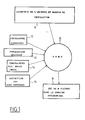
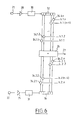
- Fig. 1 symbolically shows the SDMP 10 organization chart which receives input data of a set 11 containing the digital data relating to the topographic location of the antenna sensors as well as the useful source, a set 12 containing the data relating to the linear constraints, of a set 13 containing the data relating to the spatial weighting, of a set 14 containing the data relating to the constraints on the chosen reduction of the inconsistent noise, and a set 15 containing the data relating to the definitions of the sub-antennas.
- the flowchart 10 delivers output data to a set 16, the data of output being relative to a set of coefficients of M digital filters in the domain frequency, M being equal to the number of sensors of the antenna.
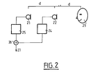
- the antenna is formed by two acoustic sensors or microphones 21 and 22 placed one behind the other in relation to a useful speaker or acoustic source 23.
- the sensors 21 and 22 and the useful source 23 are aligned.
- the distance d between sensors is, for example, 30 cm and is equal to the distance from sensor 21 to the source 23.
- This very simple antenna thus symbolizes sound pickup in the near field.
- the two sensors have a omnidirectional directivity diagram.
- the outputs of sensors 21 and 22 are respectively connected to the inputs of low-pass filters 24 and 25 whose outputs are connected to the inputs of a summator 26 which outputs the antenna output signal at 27.
- the useful signal is also added in phase, but the amplitude of the signal on the sensor 2 is two times smaller than on the sensor 1, which leads to an amplification of the power of the useful signal equal to:
- the directivity factor tends to infinity if the frequency tends to zero.
- the processing is less robust, because the useful signal is weak at the output.
- FIG. 5 shows an embodiment of a processing - filtering, summation - at the output of sensors 21 and 22 in the field temporal.
- the outputs of sensors 21 and 22 are respectively connected to the inputs microphone amplifiers 28 and 29 whose outputs are respectively connected at the inputs of analog-digital converters 30 and 31 whose outputs are respectively connected to the memory inputs 32 and 33 made up of registers with shift comprising, for example, thirty-two cells each.
- the lateral exit of a memory cell 30, associated with sensor 24, is connected to a door input 34.1.n whose second input receives a signal of coefficient h.l.n.
- the lateral exit of a memory cell 31, associated with sensor 25, is connected to a door entry 34.2.n whose second input receives a signal of coefficient h.2.n.
- the parameters n mentioned above vary discreetly from one to thirty-two depending on the rank of the cell in the shift register.
- the outputs of doors 34.1.n and 34.2.n are connected to the corresponding inputs of a digital summator 26 whose output delivers at 27 the antenna signal.
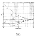
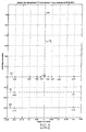
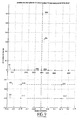
- Fig. 6 the variation of the directivity factor as a function of the frequency, in hypothesis (a), is indicated by the curve al, which decreases from 25 dB to 5 dB below of 100 Hz, shows that we improve performance at low frequencies compared to those of a conventional antenna indicated by the curve Id.
- the curve 2a indicates the variation of the reduction.
- curve 1b shows that the low frequency performance up to 5 dB, i.e. where solutions classics don't work well.
- Curve 2b corresponds to the variation of the minimum reduction imposed.
- curve 1c shows that we can gain between 2 dB for low frequencies and 0.6 dB for high.
- Line 2c identical to line 2d corresponds to the variation of the minimum reduction imposed.
- a useful source 100 U-shaped antenna comprising thirteen sensors 101 to 113 which in the example described are forward directional cardioid pattern sensors, i.e. the region containing source 100 relative to the antenna.
- the first nine sensors 101 at 109 are aligned symmetrically around the sensor 105 on a first straight line D1
- the two following sensors 110 and 111 are arranged on a second straight line D2
- the two last sensors 112 and 113 on a third straight line D3.
- Lines D1, D2 and D3 are parallel and perpendicular to a straight line D4 passing through the sensor 105 and on which the useful source 100 is installed.
- the distance from the source 100 to the right D1 is 60 cm and the lines D2 and D3 are respectively placed behind the right D1 at 15 and 30 cm.
- the sensors 110 and 112 are aligned behind the sensor 101 and sensors 111 and 113 are aligned behind sensor 109 so that train the legs of the U.
- the intervals between the sensors 105, 104, 103, 102 and 101 vary increasing logarithmically and symmetrically to intervals between sensors 105, 106, 107, 108 and 109.
- the interval is 2.5 cm; between 104 and 103, it is 2.5 cm; between 103 and 102, 5 cm; and between 102 and 101, 10 cm
- the sensor 110 is placed 15 cm behind sensor 101, like 111 behind 109, and sensor 112 is placed 15 cm behind the sensor 110, like 113 behind 112.
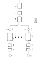
- FIG. 8 illustrates the frequency implementation of the filtering output signals from sensors 101 to 113 in Fig. 7.
- the sensor 101 supplies a amplifier A01 followed by an analog-digital converter B01 followed by a circuit C01 operating according to the Fast Fourier transformation algorithm (TFR with zero padding) connected to the serial input of a D01 filter whose output is connected to an input corresponding of an SOM adder.
- TFR Fast Fourier transformation algorithm
- the parallel input of filter D01 receives the clearance coefficients calculated by the SDMP flowchart for this filter.
- Fig. 8 we have included the sensor 113 which supplies an amplifier A13 followed by an analog-digital converter B13 followed by a circuit c13, operating like circuit C01, connected to the serial input of a filter D13, the output of which is connected to a corresponding input of the SOM adder.
- the parallel input of filter D13 receives also a set of coefficients calculated by the SDMP organization chart.
- the output of the SOM adder is connected to a circuit E operating according to a Reverse Fast Fourier Transformation algorithm (TFRI with Overlap Add) followed by a digital analog converter F which delivers the output signal from the antenna. .
- TFRI with Overlap Add Reverse Fast Fourier Transformation algorithm
- the algorithm can be performed in real time using a DSP (Texas Instruments C50).
- the antenna of FIG. 7 in four sub-antennas including the first three, in which the sensors 101 to 109 operate from the line D1, are used to cover three octaves at high frequencies and the fourth in which all the sensors 101 to 113 intervene is used for cover low frequencies from 0 to 1 kHz.
- the sensors 101 to 109 are symmetrically distributed in a logarithmic manner, which allows in a way known per se to reduce the number of sensors, here to nine. A number of five sensors per octave band is sufficient.
- the sensors 103 to 107 are used, constituting the first sub-antenna, for the band 4 to 7 kHz; sensors 102, 103, 105, 107 and 108, constituting the second sub-antenna, for the band 2 to 4 kHz; and the sensors 101, 102, 105, 108 and 109, constituting the third sub-antenna, for the band 1 to 2 kHz.
- the processing involves all the sensors 101 to 113 using the algorithm of the invention, that is to say taking into account the module differences and phase differences on sensors 110 to 113, of a similar to the processing mentioned above for the antenna of FIG. 2.
- the treatment according to the invention is useful for a wide band of frequencies, for example for speech a band going from 20 Hz to 7 kHz.
- a variant of the antenna of FIG. 6 comprises, opposite a source useful 200, thirteen sensors 201 to 213 with directivity diagram in cardioid.
- the nine first sensors 201 to 209 are symmetrically aligned around the sensor 205 on a first straight line D1, the two sensors along 210 and 211 are arranged on a second line D2 and the last two sensors 212 and 213 on a third line D3.
- Lines D1 to D3 are parallel and perpendicular to a line D4 passing through the sensor 205 and the useful source 200.
- the mutual distances between the lines D1 to D3 and the source 200 are identical to those mentioned in About the antenna of Fig. 6.
- the mutual distances between the sensors 201 to 209 are identical to those that exist between sensors 101 to 109.
- Sensors 210 and 212 are aligned behind the middle of segment 201-202 and the sensors 211 and 213 aligned behind the middle of the segment 208-209. In depth, their mutual distances are the same as in FIG. 7. The offsets of the sensors 210 at 213 towards the center of the antenna earns it the antenna designation in Pi.
- Pi antenna output signals are processed according to the flowchart superdirective-module-phase of the invention.
- FIG. 10 another variant of the antenna of FIG. 6 has in front of a useful source 300, thirteen sensors 301 to 313 with a cardioid directivity diagram.
- the first nine sensors 301 to 309 have, on the right Dl, the same arrangement as the first nine sensors of FIG. 6.
- the last four sensors 310 to 313 are successively aligned according to the same line D4 in FIG. 6, behind 305 so as to form, with the sensors 301 to 309, a T-shaped antenna.
- the distance between the sensors 310 and 305 is 10 cm, as between sensors 311 and 310, between 312 and 311, and between 313 and 312.
- T-antenna output signals are processed according to the flowchart superdirective-module-phase of the invention.
- a set 11 which contains the digital data relating to the topographic location of the antenna sensors as well as the useful source. This set 11 still contains data relating to the propagation and / or, as mentioned above, measures of responses impulse.
Landscapes
- Health & Medical Sciences (AREA)
- General Health & Medical Sciences (AREA)
- Otolaryngology (AREA)
- Physics & Mathematics (AREA)
- Engineering & Computer Science (AREA)
- Acoustics & Sound (AREA)
- Signal Processing (AREA)
- Variable-Direction Aerials And Aerial Arrays (AREA)
- Circuit For Audible Band Transducer (AREA)
- Measurement Of Velocity Or Position Using Acoustic Or Ultrasonic Waves (AREA)
- Obtaining Desirable Characteristics In Audible-Bandwidth Transducers (AREA)
Applications Claiming Priority (2)
| Application Number | Priority Date | Filing Date | Title |
|---|---|---|---|
| FR9711458 | 1997-09-10 | ||
| FR9711458A FR2768290B1 (fr) | 1997-09-10 | 1997-09-10 | Antenne formee d'une pluralite de capteurs acoustiques |
Publications (2)
| Publication Number | Publication Date |
|---|---|
| EP0903960A1 true EP0903960A1 (de) | 1999-03-24 |
| EP0903960B1 EP0903960B1 (de) | 2003-10-29 |
Family
ID=9511091
Family Applications (1)
| Application Number | Title | Priority Date | Filing Date |
|---|---|---|---|
| EP98460031A Expired - Lifetime EP0903960B1 (de) | 1997-09-10 | 1998-08-13 | Antenne gebildet durch eine Vielzahl von akustischen Detektoren |
Country Status (5)
| Country | Link |
|---|---|
| US (1) | US6160757A (de) |
| EP (1) | EP0903960B1 (de) |
| JP (1) | JP4491081B2 (de) |
| DE (1) | DE69819273T2 (de) |
| FR (1) | FR2768290B1 (de) |
Cited By (1)
| Publication number | Priority date | Publication date | Assignee | Title |
|---|---|---|---|---|
| US7292833B2 (en) * | 2000-04-28 | 2007-11-06 | France Telecom, Sa | Reception system for multisensor antenna |
Families Citing this family (16)
| Publication number | Priority date | Publication date | Assignee | Title |
|---|---|---|---|---|
| US6978159B2 (en) * | 1996-06-19 | 2005-12-20 | Board Of Trustees Of The University Of Illinois | Binaural signal processing using multiple acoustic sensors and digital filtering |
| US6987856B1 (en) | 1996-06-19 | 2006-01-17 | Board Of Trustees Of The University Of Illinois | Binaural signal processing techniques |
| US7157649B2 (en) * | 1999-12-23 | 2007-01-02 | New Transducers Limited | Contact sensitive device |
| CN1440628A (zh) | 2000-05-10 | 2003-09-03 | 伊利诺伊大学评议会 | 干扰抑制技术 |
| GB0116310D0 (en) * | 2001-07-04 | 2001-08-29 | New Transducers Ltd | Contact sensitive device |
| US7274794B1 (en) | 2001-08-10 | 2007-09-25 | Sonic Innovations, Inc. | Sound processing system including forward filter that exhibits arbitrary directivity and gradient response in single wave sound environment |
| WO2003015459A2 (en) * | 2001-08-10 | 2003-02-20 | Rasmussen Digital Aps | Sound processing system that exhibits arbitrary gradient response |
| US6937938B2 (en) | 2002-09-04 | 2005-08-30 | Stanley A. Sansone | Method and apparatus for interferometry, spectral analysis, and three-dimensional holographic imaging of hydrocarbon accumulations and buried objects |
| US6871149B2 (en) * | 2002-12-06 | 2005-03-22 | New Transducers Limited | Contact sensitive device |
| US7512448B2 (en) | 2003-01-10 | 2009-03-31 | Phonak Ag | Electrode placement for wireless intrabody communication between components of a hearing system |
| US7945064B2 (en) * | 2003-04-09 | 2011-05-17 | Board Of Trustees Of The University Of Illinois | Intrabody communication with ultrasound |
| US7076072B2 (en) | 2003-04-09 | 2006-07-11 | Board Of Trustees For The University Of Illinois | Systems and methods for interference-suppression with directional sensing patterns |
| US7317764B2 (en) * | 2003-06-11 | 2008-01-08 | Lucent Technologies Inc. | Method of signal transmission to multiple users from a multi-element array |
| WO2005115050A1 (en) * | 2004-05-19 | 2005-12-01 | Harman International Industries, Incorporated | Vehicle loudspeaker array |
| WO2008156700A2 (en) * | 2007-06-15 | 2008-12-24 | Worcester Polytechnic Institute | Precision location methods and systems |
| BRPI0910799A2 (pt) * | 2008-07-08 | 2015-09-29 | Koninkl Philips Electronics Nv | método, método de operar uma pluralidade de unidades de iluminação, e, aparelho |
Citations (2)
| Publication number | Priority date | Publication date | Assignee | Title |
|---|---|---|---|---|
| US4536887A (en) * | 1982-10-18 | 1985-08-20 | Nippon Telegraph & Telephone Public Corporation | Microphone-array apparatus and method for extracting desired signal |
| EP0652686A1 (de) * | 1993-11-05 | 1995-05-10 | AT&T Corp. | Adaptive Mikrophongruppierung |
Family Cites Families (1)
| Publication number | Priority date | Publication date | Assignee | Title |
|---|---|---|---|---|
| US5715319A (en) * | 1996-05-30 | 1998-02-03 | Picturetel Corporation | Method and apparatus for steerable and endfire superdirective microphone arrays with reduced analog-to-digital converter and computational requirements |
-
1997
- 1997-09-10 FR FR9711458A patent/FR2768290B1/fr not_active Expired - Lifetime
-
1998
- 1998-08-13 DE DE69819273T patent/DE69819273T2/de not_active Expired - Lifetime
- 1998-08-13 EP EP98460031A patent/EP0903960B1/de not_active Expired - Lifetime
- 1998-08-20 US US09/137,036 patent/US6160757A/en not_active Expired - Lifetime
- 1998-09-09 JP JP25518298A patent/JP4491081B2/ja not_active Expired - Lifetime
Patent Citations (2)
| Publication number | Priority date | Publication date | Assignee | Title |
|---|---|---|---|---|
| US4536887A (en) * | 1982-10-18 | 1985-08-20 | Nippon Telegraph & Telephone Public Corporation | Microphone-array apparatus and method for extracting desired signal |
| EP0652686A1 (de) * | 1993-11-05 | 1995-05-10 | AT&T Corp. | Adaptive Mikrophongruppierung |
Non-Patent Citations (3)
| Title |
|---|
| F.KHALIL,J.P.JULLIEN,A.GILLOIRE: "MICROPHONE ARRAY FOR SOUND PICKUP IN TELECONFERENCE SYSTEM", JOURNAL OF AUDIO ENG.SSOC., vol. 42, no. 9, September 1994 (1994-09-01), U.S.A., pages 691 - 700, XP000699730 * |
| MAN MOHAN SONDHI,GARY W. ELKO: "ADAPTIVE OPTIMIZATION OF MICROPHONE ARRAYS UNDER A NON LINEAR CONSTRAINT", ICASSP 86 PROCEEDINGS, vol. 2, April 1986 (1986-04-01), TOKYO, pages 981 - 984, XP002067510 * |
| VON RAINER ZELINSKI: "MIKROFON-ARRAYS MIT SUPERDIREKTIVEN EINGESCHAFTEN ZUR SPRACHSIGNALÜBERTRAGUNG", FREQUENZ, no. 50, September 1996 (1996-09-01), pages 198 - 204, XP000678040 * |
Cited By (1)
| Publication number | Priority date | Publication date | Assignee | Title |
|---|---|---|---|---|
| US7292833B2 (en) * | 2000-04-28 | 2007-11-06 | France Telecom, Sa | Reception system for multisensor antenna |
Also Published As
| Publication number | Publication date |
|---|---|
| FR2768290B1 (fr) | 1999-10-15 |
| FR2768290A1 (fr) | 1999-03-12 |
| US6160757A (en) | 2000-12-12 |
| EP0903960B1 (de) | 2003-10-29 |
| DE69819273T2 (de) | 2004-07-22 |
| DE69819273D1 (de) | 2003-12-04 |
| JP4491081B2 (ja) | 2010-06-30 |
| JPH11146494A (ja) | 1999-05-28 |
Similar Documents
| Publication | Publication Date | Title |
|---|---|---|
| EP0903960B1 (de) | Antenne gebildet durch eine Vielzahl von akustischen Detektoren | |
| EP0605281B1 (de) | Verfahren für die vektorielle Sprachrauschunterdrückung und Gerät zu seiner Durchführung | |
| EP2122607B1 (de) | Verfahren zur aktiven minderung von störgeräuschen | |
| EP2680262B1 (de) | Verfahren zur Geräuschdämpfung eines Audiosignals für eine Multimikrofon-Audiovorrichtung, die in lauten Umgebungen eingesetzt wird | |
| Teutsch et al. | Acoustic source detection and localization based on wavefield decomposition using circular microphone arrays | |
| FR2472326A1 (fr) | Reseau de microphones a diagramme directionnel | |
| JP2009506683A (ja) | 強調された位相差値を使用して雑音弁別を改良するための方法および装置 | |
| JP2009506363A (ja) | センサアレイにおけるデバイスおよび/または信号のミスマッチに適応するための方法および装置 | |
| JP2009506672A (ja) | 減衰ファクタを用いて雑音弁別を改良するための方法および装置 | |
| FR2828327A1 (fr) | Procede et dispositif de reduction d'echo | |
| EP0015852B1 (de) | Gerät zur Messung der Leistung eines gerichteten Schallbündels oder der akustischen Gesamtleistung die von einer Schallquelle ausgestrahlt wird | |
| EP1277372B1 (de) | Empfangssystem für eine mehrfachempfänger -antenne | |
| Benesty et al. | Array beamforming with linear difference equations | |
| Hines et al. | Evaluation of the endfire response of a superdirective line array in simulated ambient noise environments | |
| Berkun et al. | A tunable beamformer for robust superdirective beamforming | |
| EP1438871B1 (de) | Anordnung zur tonaufnahme und tonwiedergabe mittels einer vielzahl von sensoren | |
| FR2858512A1 (fr) | Procede et dispositif de traitement de donnees sonores en contexte ambiophonique | |
| EP1155497B1 (de) | System und verfahren zum verarbeiten von antennensignalen | |
| CA2031719C (fr) | Procede et dispositif pour imposer un diagramme de rayonnement au repos a un reseau d'antennes de reception a formation adaptative de faisceau par le calcul | |
| FR3116401A1 (fr) | Procédé de traitement d’un signal GNSS en vue d’atténuer au moins un signal de brouillage | |
| Levi et al. | An alternate approach to adaptive beamforming using srp-phat | |
| FR2967861A1 (fr) | Systeme electroacoustique pour une salle de spectacle | |
| JP3627138B2 (ja) | 雑音白色化方法 | |
| WO2022170541A1 (en) | First-order differential microphone array with steerable beamformer | |
| Pedamallu | Microphone Array Wiener Beamforming with emphasis on Reverberation |
Legal Events
| Date | Code | Title | Description |
|---|---|---|---|
| PUAI | Public reference made under article 153(3) epc to a published international application that has entered the european phase |
Free format text: ORIGINAL CODE: 0009012 |
|
| AK | Designated contracting states |
Kind code of ref document: A1 Designated state(s): DE GB IT |
|
| AX | Request for extension of the european patent |
Free format text: AL;LT;LV;MK;RO;SI |
|
| 17P | Request for examination filed |
Effective date: 19990406 |
|
| AKX | Designation fees paid |
Free format text: DE GB IT |
|
| GRAH | Despatch of communication of intention to grant a patent |
Free format text: ORIGINAL CODE: EPIDOS IGRA |
|
| GRAS | Grant fee paid |
Free format text: ORIGINAL CODE: EPIDOSNIGR3 |
|
| GRAA | (expected) grant |
Free format text: ORIGINAL CODE: 0009210 |
|
| AK | Designated contracting states |
Kind code of ref document: B1 Designated state(s): DE GB IT |
|
| REG | Reference to a national code |
Ref country code: GB Ref legal event code: FG4D Free format text: NOT ENGLISH |
|
| GBT | Gb: translation of ep patent filed (gb section 77(6)(a)/1977) |
Effective date: 20031029 |
|
| REF | Corresponds to: |
Ref document number: 69819273 Country of ref document: DE Date of ref document: 20031204 Kind code of ref document: P |
|
| PLBE | No opposition filed within time limit |
Free format text: ORIGINAL CODE: 0009261 |
|
| STAA | Information on the status of an ep patent application or granted ep patent |
Free format text: STATUS: NO OPPOSITION FILED WITHIN TIME LIMIT |
|
| 26N | No opposition filed |
Effective date: 20040730 |
|
| PGFP | Annual fee paid to national office [announced via postgrant information from national office to epo] |
Ref country code: IT Payment date: 20080812 Year of fee payment: 11 |
|
| REG | Reference to a national code |
Ref country code: GB Ref legal event code: 732E Free format text: REGISTERED BETWEEN 20100812 AND 20100818 |
|
| PG25 | Lapsed in a contracting state [announced via postgrant information from national office to epo] |
Ref country code: IT Free format text: LAPSE BECAUSE OF NON-PAYMENT OF DUE FEES Effective date: 20090813 |
|
| PGFP | Annual fee paid to national office [announced via postgrant information from national office to epo] |
Ref country code: DE Payment date: 20170825 Year of fee payment: 20 Ref country code: GB Payment date: 20170725 Year of fee payment: 20 |
|
| REG | Reference to a national code |
Ref country code: DE Ref legal event code: R071 Ref document number: 69819273 Country of ref document: DE |
|
| REG | Reference to a national code |
Ref country code: GB Ref legal event code: PE20 Expiry date: 20180812 |
|
| PG25 | Lapsed in a contracting state [announced via postgrant information from national office to epo] |
Ref country code: GB Free format text: LAPSE BECAUSE OF EXPIRATION OF PROTECTION Effective date: 20180812 |