EP0903868A1 - Lecteur de cartes à puce avec adaptateur pour lire des formats de cartes différents, téléphone comportant un tel lecteur - Google Patents
Lecteur de cartes à puce avec adaptateur pour lire des formats de cartes différents, téléphone comportant un tel lecteur Download PDFInfo
- Publication number
- EP0903868A1 EP0903868A1 EP98202749A EP98202749A EP0903868A1 EP 0903868 A1 EP0903868 A1 EP 0903868A1 EP 98202749 A EP98202749 A EP 98202749A EP 98202749 A EP98202749 A EP 98202749A EP 0903868 A1 EP0903868 A1 EP 0903868A1
- Authority
- EP
- European Patent Office
- Prior art keywords
- card
- plate
- connector
- card reader
- small
- Prior art date
- Legal status (The legal status is an assumption and is not a legal conclusion. Google has not performed a legal analysis and makes no representation as to the accuracy of the status listed.)
- Withdrawn
Links
Images
Classifications
-
- G—PHYSICS
- G06—COMPUTING; CALCULATING OR COUNTING
- G06K—GRAPHICAL DATA READING; PRESENTATION OF DATA; RECORD CARRIERS; HANDLING RECORD CARRIERS
- G06K7/00—Methods or arrangements for sensing record carriers, e.g. for reading patterns
- G06K7/0013—Methods or arrangements for sensing record carriers, e.g. for reading patterns by galvanic contacts, e.g. card connectors for ISO-7816 compliant smart cards or memory cards, e.g. SD card readers
- G06K7/0052—Methods or arrangements for sensing record carriers, e.g. for reading patterns by galvanic contacts, e.g. card connectors for ISO-7816 compliant smart cards or memory cards, e.g. SD card readers connectors capable of contacting cards of different formats, e.g. memory stick and SD card readers sharing at least one connector contact and the associated signal line, e.g. both using the same signal line for input or output of data
-
- G—PHYSICS
- G06—COMPUTING; CALCULATING OR COUNTING
- G06K—GRAPHICAL DATA READING; PRESENTATION OF DATA; RECORD CARRIERS; HANDLING RECORD CARRIERS
- G06K7/00—Methods or arrangements for sensing record carriers, e.g. for reading patterns
- G06K7/0013—Methods or arrangements for sensing record carriers, e.g. for reading patterns by galvanic contacts, e.g. card connectors for ISO-7816 compliant smart cards or memory cards, e.g. SD card readers
- G06K7/0021—Methods or arrangements for sensing record carriers, e.g. for reading patterns by galvanic contacts, e.g. card connectors for ISO-7816 compliant smart cards or memory cards, e.g. SD card readers for reading/sensing record carriers having surface contacts
-
- G—PHYSICS
- G06—COMPUTING; CALCULATING OR COUNTING
- G06K—GRAPHICAL DATA READING; PRESENTATION OF DATA; RECORD CARRIERS; HANDLING RECORD CARRIERS
- G06K7/00—Methods or arrangements for sensing record carriers, e.g. for reading patterns
- G06K7/0013—Methods or arrangements for sensing record carriers, e.g. for reading patterns by galvanic contacts, e.g. card connectors for ISO-7816 compliant smart cards or memory cards, e.g. SD card readers
- G06K7/0034—Methods or arrangements for sensing record carriers, e.g. for reading patterns by galvanic contacts, e.g. card connectors for ISO-7816 compliant smart cards or memory cards, e.g. SD card readers the connector being capable of simultaneously receiving a plurality of cards in the same insertion slot
- G06K7/0043—Methods or arrangements for sensing record carriers, e.g. for reading patterns by galvanic contacts, e.g. card connectors for ISO-7816 compliant smart cards or memory cards, e.g. SD card readers the connector being capable of simultaneously receiving a plurality of cards in the same insertion slot the plurality of cards being cards of different formats, e.g. SD card and memory stick
-
- H—ELECTRICITY
- H04—ELECTRIC COMMUNICATION TECHNIQUE
- H04B—TRANSMISSION
- H04B1/00—Details of transmission systems, not covered by a single one of groups H04B3/00 - H04B13/00; Details of transmission systems not characterised by the medium used for transmission
- H04B1/38—Transceivers, i.e. devices in which transmitter and receiver form a structural unit and in which at least one part is used for functions of transmitting and receiving
- H04B1/3816—Mechanical arrangements for accommodating identification devices, e.g. cards or chips; with connectors for programming identification devices
-
- H—ELECTRICITY
- H04—ELECTRIC COMMUNICATION TECHNIQUE
- H04M—TELEPHONIC COMMUNICATION
- H04M1/00—Substation equipment, e.g. for use by subscribers
- H04M1/02—Constructional features of telephone sets
- H04M1/0202—Portable telephone sets, e.g. cordless phones, mobile phones or bar type handsets
-
- H—ELECTRICITY
- H04—ELECTRIC COMMUNICATION TECHNIQUE
- H04M—TELEPHONIC COMMUNICATION
- H04M1/00—Substation equipment, e.g. for use by subscribers
- H04M1/02—Constructional features of telephone sets
- H04M1/0202—Portable telephone sets, e.g. cordless phones, mobile phones or bar type handsets
- H04M1/026—Details of the structure or mounting of specific components
- H04M1/0274—Details of the structure or mounting of specific components for an electrical connector module
-
- H—ELECTRICITY
- H04—ELECTRIC COMMUNICATION TECHNIQUE
- H04M—TELEPHONIC COMMUNICATION
- H04M2250/00—Details of telephonic subscriber devices
- H04M2250/14—Details of telephonic subscriber devices including a card reading device
Definitions
- the invention relates to an electronic card reader comprising a connector and adaptation means for reading a large or a small card having the same contact configuration.
- the invention also relates to a telephone incorporating such a reader.
- card for reading a large card called ISO SIM card, or a small card called card Micro SIM.
- the invention has important applications in the field of telephony mobile and in particular the GSM standard which provides for the use of two different formats for the SIM card, from the English Suscriber Identity Module.
- European patent application No. 0556970 A1 describes a radiotelephone which is suitable for receiving either of the two formats of SIM cards.
- This radiotelephone includes an adapter which, for reading a large card, is placed in a cavity so not to obstruct the passage of the card, and which, for the reading of a small card, switches by means of a pivot link and plates the contacts of the integrated circuit of the card on the card reader connector.
- a card reader according to the invention and as described in the introductory paragraph is characterized in that said adaptation means comprise a plate intended to be move between an open position in particular to insert a small card in a housing provided around said connector and a closed position in particular for hold in place the small card previously introduced, said plate being provided with a opening made around said connector making it possible to establish contact between said connector connector and a large card previously placed on the plate.
- the plate includes means for exerting contact pressure on a small card inserted into said housing, and the reader comprises means for returning the plate in closed position.
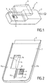
- FIG 1 there is shown schematically a telephone 1 according to the invention.
- This phone 1 has a main box 2, and a removable module 3 which serves cover on the phone and which contains for example a battery for power supply telephone.
- the main housing 2 contains a printed circuit board 5 to which a connector 4 is fixed among other components a smart card reader.
- the housing 2 serves as a frame for the smart card reader.
- the connector 4 is provided with spring contact fingers 6 intended to be brought into contact with the terminals of the integrated circuit of a smart card.
- a plastic support 7 is placed above the printed circuit board. It has an opening 8 to let through the fingers of the connector 4, and of a housing 9 formed around this opening 8 and intended to receive a small format smart card, or Micro SIM card.
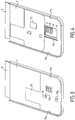
- a drawer plate 10 ( Figures 3 and 4), placed above the support 7, is intended to slide in slides 11a and 11b provided on the sides of the main housing 2, as well as in a slide 11c, called the central slide, which is formed in the support 7 along the opening 8.
- the drawer plate has feet 12a and 12b engaged in the central slide 11c: these feet 12a and 12b are L-shaped, cut from the plate drawer 10 and folded perpendicular to the plate. The use of such a central slide allows sufficient pressure to be exerted on a small card inserted in the housing 9 to ensure electrical contact with the fingers of connector 4.
- the drawer plate 10 is shown in the closed position, and on Figure 4 it is shown in the open position.
- the open position allows to introduce a small Micro SIM card in the slot 9.
- the plate 10 allows to keep the small card in place, and to exert sufficient pressure to that electrical contact is established between the integrated circuit of the small card and the fingers of the connector.
- the drawer plate In the absence of a small card, the drawer plate is intended to serve as a support for a large card in ISO SIM format.
- the integrated circuit of the card is then placed in look of an opening 13 made in the drawer plate at the connector 4 such so that electrical contact is made.
- the pressure to establish a good contact is ensured by the removable module 3 when it is in place on the housing main phone.
- the contact finger springs of connector 4 are springs long-stroke so as to ensure contact with the two types of cards which, when they are in place in the phone, are at different distances from connector 4.
- return means are provided for automatically returning the drawer plate to the position closed.
- a housing 14 is provided in the support 7. This housing 14 is intended to contain a spring 15 which is fixed on the one hand to a fulcrum 16 of the drawer plate 10, and on the other hand on the support 7 or on the printed circuit board 5.
- the fulcrum 16 is cut from the drawer plate 10 and folded perpendicular to the plate.
- Spring 15 is a hairpin spring.
Abstract
L'invention a pour but de permettre la lecture d'une grande ou d'une petite carte qui présentent une même configuration de contact. Une plaque tiroir 10 est prévue à cet effet : elle coulisse entre une position ouverte et une position fermée. Lorsque la plaque est en position ouverte, une petite carte peut être introduite dans un logement 9. En position fermée la plaque permet de maintenir cette petite carte en place et d'assurer une pression suffisante pour établir le contact électrique. La plaque est dotée d'une ouverture 13 destinée à laisser passer le connecteur 4 en l'absence de petite carte : elle peut alors servir de support à une grande carte. Applications : téléphone GSM notamment. <IMAGE>
Description
L'invention concerne un lecteur de carte électronique comportant un
connecteur et des moyens d'adaptation pour la lecture d'une grande ou d'une petite carte
ayant une même configuration de contact.
L'invention concerne également un téléphone incorporant un tel lecteur de
carte, pour la lecture d'une grande carte dite carte ISO SIM, ou d'une petite carte dite carte
Micro SIM.
L'invention a d'importantes applications dans le domaine de la téléphonie
mobile et notamment de la norme GSM qui prévoit l'utilisation de deux formats différents
pour la carte SIM, de l'anglais Suscriber Identity Module.
La demande de brevet européen n° 0556970 A1 décrit un radiotéléphone
qui est apte à recevoir l'un ou l'autre des deux formats de cartes SIM. Ce radiotéléphone
comporte un adapteur qui, pour la lecture d'une grande carte, est placé dans une cavité afin
de ne pas faire obstacle au passage de la carte, et qui, pour la lecture d'une petite carte,
bascule au moyen d'une liaison pivot et plaque les contacts du circuit intégré de la carte sur
le connecteur du lecteur de carte.
Cette solution présente l'inconvénient suivant : lors du basculement de
l'adaptateur celui-ci fait saillie avec le corps du téléphone et devient alors vulnérable aux
chocs. Un choc transversal risque en effet de briser certaines des parties formant la liaison
pivot, désolidarisant ainsi irrémédiablement l'adaptateur du corps du téléphone.
De plus, cette solution est relativement encombrante, ce qui va à l'encontre
de la tendance actuelle à la miniaturisation des téléphones mobiles.
L'invention a notamment pour but de remédier à ces inconvénients. Pour
cela, un lecteur de carte selon l'invention et tel que décrit dans le paragraphe introductif est
caractérisé en ce que lesdits moyens d'adaptation comportent une plaque destinée à se
déplacer entre une position ouverte notamment pour introduire une petite carte dans un
logement pratiqué autour dudit connecteur et une position fermée notamment pour
maintenir en place la petite carte préalablement introduite, ladite plaque étant dotée d'une
ouverture pratiquée autour dudit connecteur permettant d'établir un contact entre ledit
connecteur et une grande carte préalablement placée sur la plaque.
Dans des modes de réalisation particulièrement avantageux de l'invention,
la plaque comporte des moyens pour exercer une pression de contact sur une petite carte
introduite dans ledit logement, et le lecteur comporte des moyens de rappel de la plaque en
position fermée.
L'invention sera mieux comprise et d'autres détails apparaítront à la lumière
de la description qui va suivre en regard des dessins annexés qui sont donnés à titre
d'exemples non limitatifs et dans lesquels :
- la figure 1 représente un téléphone selon l'invention,
- la figure 2 est une représentation schématique d'une vue arrière d'un boítier principal d'un téléphone selon l'invention, sans plaque,
- la figure 3 est une représentation schématique d'une vue arrière d'un boítier principal d'un téléphone selon l'invention, avec une plaque en position fermée,
- la figure 4 est une représentation schématique d'une vue arrière d'un boítier principal d'un téléphone selon l'invention, avec une plaque en position ouverte.
Sur la figure 1, on a représenté schématiquement un téléphone 1 selon
l'invention. Ce téléphone 1 comporte un boítier principal 2, et un module amovible 3 qui sert
de couvercle au téléphone et qui contient par exemple une batterie pour l'alimentation
électrique du téléphone.
Comme représenté sur les figures 1 et 2, le boítier principal 2 contient une
carte de circuits imprimés 5 sur laquelle est fixée entre autres composants un connecteur 4
d'un lecteur de carte à puce. Le boítier 2 sert de bâti au lecteur de carte à puce. Le
connecteur 4 est doté de doigts de contact à ressorts 6 destinés à être mis en contact avec
les bornes du circuit intégré d'une carte à puce. Un support 7 en matière plastique est placé
au-dessus de la carte de circuits imprimés. Il est doté d'une ouverture 8 pour laisser passer
les doigts du connecteur 4, et d'un logement 9 pratiqué autour de cette ouverture 8 et
destiné à recevoir une carte à puce de petit format, ou carte Micro SIM.
Une plaque tiroir 10 (figures 3 et 4), placée au dessus du support 7, est
destinée à coulisser dans des glissières 11a et 11b prévues sur les côtés du boítier principal
2, ainsi que dans une glissière 11c, dite glissière centrale, qui est pratiquée dans le support
7 le long de l'ouverture 8. La plaque tiroir est dotée de pieds 12a et 12b engagés dans la
glissière centrale 11c : ces pieds 12a et 12b sont en forme de L, découpés dans la plaque
tiroir 10 et repliés perpendiculairement à la plaque. L'utilisation d'une telle glissière centrale
permet d'exercer une pression suffisante sur une petite carte introduite dans le logement 9
pour assurer le contact électrique avec les doigts du connecteur 4.
Sur la figure 3, la plaque tiroir 10 est représentée en position fermée, et sur
la figure 4 elle est représentée en position ouverte. La position ouverte permet d'introduire
une petite carte au format Micro SIM dans le logement 9. En position fermée, la plaque 10
permet alors de maintenir la petite carte en place, et d'exercer une pression suffisante pour
que le contact électrique soit établi entre le circuit intégré de la petite carte et les doigts du
connecteur. En l'absence de petite carte, la plaque tiroir est destinée à servir de support à
une grande carte au format ISO SIM. Le circuit intégré de la carte vient alors se placer en
regard d'une ouverture 13 pratiquée dans la plaque tiroir au niveau du connecteur 4 de telle
sorte que le contact électrique soit établi. La pression nécessaire à l'établissement d'un bon
contact est assurée par le module amovible 3 lorsque celui-ci est en place sur le boítier
principal du téléphone. Les ressorts des doigts de contact du connecteur 4 sont des ressorts
à course longue de façon à assurer un contact avec les deux types de cartes qui, lorsqu'elles
sont en place dans le téléphone, se situent à des distances différentes du connecteur 4.
Dans un mode de réalisation particulièrement simple à manipuler, des
moyens de rappel sont prévus pour ramener automatiquement la plaque tiroir en position
fermée. Pour cela, un logement 14 est prévu dans le support 7. Ce logement 14 est destiné
à contenir un ressort 15 qui est fixé d'une part sur un point d'appui 16 de la plaque tiroir 10,
et d'autre part sur le support 7 ou sur la carte à circuits imprimés 5. Le point d'appui 16 est
découpé dans la plaque tiroir 10 et replié perpendiculairement à la plaque. Le ressort 15 est
un ressort en épingle à cheveux.
Claims (7)
- Lecteur de carte électronique comportant un connecteur (4) et des moyens d'adaptation pour la lecture d'une grande ou d'une petite carte ayant une même configuration de contact, caractérisé en ce que lesdits moyens d'adaptation comportent une plaque (10) destinée à se déplacer entre une position ouverte notamment pour introduire une petite carte dans un logement (9) pratiqué autour dudit connecteur et une position fermée notamment pour maintenir en place la petite carte préalablement introduite, ladite plaque étant dotée d'une ouverture (13) pratiquée autour dudit connecteur permettant d'établir un contact entre ledit connecteur et une grande carte préalablement placée sur la plaque.
- Lecteur de carte selon la revendication 1, caractérisé en ce que ladite plaque comporte des moyens (11c, 12a, 12b) pour exercer une pression de contact sur une petite carte introduite dans ledit logement.
- Lecteur de carte selon l'une des revendications 1 ou 2, caractérisé en ce qu'il comporte des moyens de rappel (14, 15, 16) de ladite plaque en position fermée.
- Lecteur de carte selon la revendication 1, caractérisé en ce qu'il comporte un bâti (2) doté de glissières (11a, 11b) et en ce que la plaque est une plaque tiroir coulissant dans lesdites glissières.
- Lecteur de carte selon la revendication 4, caractérisé en ce que le bâti est notamment doté d'une glissière, dite glissière centrale (11c), placée le long dudit connecteur et en ce que la plaque tiroir est dotée d'au moins un pied (12a, 12b) engagé dans ladite glissière centrale de façon à exercer une pression de contact sur une petite carte introduite dans ledit logement.
- Lecteur de carte selon l'une des revendications 4 ou 5, caractérisé en ce que ledit bâti comporte un logement (14) destiné à contenir un ressort (15) dont l'une des extrémités est fixée à un point d'appui (16) de la plaque tiroir de façon à exercer une pression sur la plaque lorsqu'elle est en position ouverte pour la rappeler en position fermée.
- Téléphone (1) incorporant un lecteur de carte électronique selon l'une des revendications 1 à 6, pour la lecture d'une grande carte dite carte ISO SIM, ou d'une petite carte dite carte Micro SIM.
Applications Claiming Priority (2)
| Application Number | Priority Date | Filing Date | Title |
|---|---|---|---|
| FR9710472A FR2767625A1 (fr) | 1997-08-19 | 1997-08-19 | Lecteur de cartes a puce avec adaptateur pour lire des formats de cartes differents, telephone comportant un tel lecteur |
| FR9710472 | 1997-08-19 |
Publications (1)
| Publication Number | Publication Date |
|---|---|
| EP0903868A1 true EP0903868A1 (fr) | 1999-03-24 |
Family
ID=9510372
Family Applications (1)
| Application Number | Title | Priority Date | Filing Date |
|---|---|---|---|
| EP98202749A Withdrawn EP0903868A1 (fr) | 1997-08-19 | 1998-08-17 | Lecteur de cartes à puce avec adaptateur pour lire des formats de cartes différents, téléphone comportant un tel lecteur |
Country Status (6)
| Country | Link |
|---|---|
| US (1) | US6068186A (fr) |
| EP (1) | EP0903868A1 (fr) |
| JP (1) | JPH11155006A (fr) |
| KR (1) | KR19990023683A (fr) |
| CN (1) | CN1221159A (fr) |
| FR (1) | FR2767625A1 (fr) |
Families Citing this family (14)
| Publication number | Priority date | Publication date | Assignee | Title |
|---|---|---|---|---|
| US6293464B1 (en) * | 1999-01-05 | 2001-09-25 | Jared Joseph Smalley, Jr. | Card reader |
| JP3391375B2 (ja) * | 1999-03-02 | 2003-03-31 | 日本電気株式会社 | Icカードを備えた携帯電話機用バッテリ |
| JP2002111832A (ja) * | 2000-09-27 | 2002-04-12 | Toshiba Corp | 携帯型情報機器 |
| GB0023994D0 (en) * | 2000-09-30 | 2000-11-15 | Pace Micro Tech Plc | Improvements to a broadcast data receiver |
| US6766952B2 (en) * | 2001-11-06 | 2004-07-27 | Quadnovation, Inc. | SIM card carrier |
| KR20040028104A (ko) * | 2002-09-28 | 2004-04-03 | 주식회사 케이티 | 접촉식 2칩 카드의 칩보드 배치 방법 |
| JP4224809B2 (ja) * | 2003-03-03 | 2009-02-18 | 旭精工株式会社 | Icカード処理装置の通信基板装着装置 |
| US7376564B2 (en) * | 2005-01-18 | 2008-05-20 | Target Brands, Inc. | Stored-value card with audio capabilities |
| CN1980263B (zh) * | 2005-12-09 | 2010-08-11 | 深圳富泰宏精密工业有限公司 | 芯片卡固持结构 |
| EP1895384A1 (fr) * | 2006-08-31 | 2008-03-05 | Inventec Multimedia & Telecom Corporation | Lecteur multimédia portable extensible |
| US8573986B2 (en) | 2010-07-30 | 2013-11-05 | Sharpe Innovations, Inc. | SIM card adaptor |
| US8337239B2 (en) | 2010-07-30 | 2012-12-25 | Sharpe Innovations, Inc. | Hardened micro SIM adaptor |
| US8855715B2 (en) | 2011-03-11 | 2014-10-07 | Nokia Corporation | Apparatus and method for a removable memory module |
| CN104037571B (zh) * | 2014-06-18 | 2016-05-25 | 启东乾朔电子有限公司 | 卡连接器 |
Citations (3)
| Publication number | Priority date | Publication date | Assignee | Title |
|---|---|---|---|---|
| WO1994018644A1 (fr) * | 1993-02-12 | 1994-08-18 | Telecom Finland Oy | Cadre pour carte |
| WO1994027244A1 (fr) * | 1993-05-14 | 1994-11-24 | Amphenol-Tuchel Electronics Gmbh | Lecteur a montage en surface de cartes a module d'identification d'abonne et de cartes standard |
| EP0784382A2 (fr) * | 1996-01-10 | 1997-07-16 | Koninklijke Philips Electronics N.V. | Appareil muni d'un adaptateur permettant la lecture de cartes à puces aux formats différents |
Family Cites Families (2)
| Publication number | Priority date | Publication date | Assignee | Title |
|---|---|---|---|---|
| FI90298C (fi) * | 1992-02-18 | 1994-01-10 | Nokia Mobile Phones Ltd | Kortinlukijalaite |
| DE19506606C2 (de) * | 1995-02-24 | 1996-12-19 | Amphenol Tuchel Elect | Chipkartenleser |
-
1997
- 1997-08-19 FR FR9710472A patent/FR2767625A1/fr not_active Withdrawn
-
1998
- 1998-08-17 EP EP98202749A patent/EP0903868A1/fr not_active Withdrawn
- 1998-08-17 US US09/135,192 patent/US6068186A/en not_active Expired - Fee Related
- 1998-08-17 JP JP10230782A patent/JPH11155006A/ja active Pending
- 1998-08-18 KR KR1019980033503A patent/KR19990023683A/ko not_active Application Discontinuation
- 1998-08-19 CN CN98118457A patent/CN1221159A/zh active Pending
Patent Citations (3)
| Publication number | Priority date | Publication date | Assignee | Title |
|---|---|---|---|---|
| WO1994018644A1 (fr) * | 1993-02-12 | 1994-08-18 | Telecom Finland Oy | Cadre pour carte |
| WO1994027244A1 (fr) * | 1993-05-14 | 1994-11-24 | Amphenol-Tuchel Electronics Gmbh | Lecteur a montage en surface de cartes a module d'identification d'abonne et de cartes standard |
| EP0784382A2 (fr) * | 1996-01-10 | 1997-07-16 | Koninklijke Philips Electronics N.V. | Appareil muni d'un adaptateur permettant la lecture de cartes à puces aux formats différents |
Also Published As
| Publication number | Publication date |
|---|---|
| KR19990023683A (ko) | 1999-03-25 |
| FR2767625A1 (fr) | 1999-02-26 |
| JPH11155006A (ja) | 1999-06-08 |
| CN1221159A (zh) | 1999-06-30 |
| US6068186A (en) | 2000-05-30 |
Similar Documents
| Publication | Publication Date | Title |
|---|---|---|
| EP0942492B1 (fr) | Boítier de raccordement électronique, à un ordinateur individuel, équipé d'un connecteur pour une carte à puce | |
| EP0793189B1 (fr) | Lecteur de carte à puce de formats différents et téléphone portable incorporant un tel lecteur | |
| EP0469503B1 (fr) | Dispositif de logement d'une carte à mémoire | |
| EP0903868A1 (fr) | Lecteur de cartes à puce avec adaptateur pour lire des formats de cartes différents, téléphone comportant un tel lecteur | |
| EP0793190B1 (fr) | Lecteur de cartes pour téléphone portable et téléphone portable l'incorporant | |
| FR2692096A1 (fr) | Chambre destiné à recevoir et à retenir une carte d'informations et radiotéléphone comportant une telle chambre. | |
| FR2783622A1 (fr) | Connecteur electrique pour le raccordement simultane de deux cartes a memoire electronique | |
| EP0674287A1 (fr) | Boîtier pour lecteur de carte à microcircuit | |
| FR2742561A1 (fr) | Connecteur electrique pour une carte a circuit(s) integre(s) a contact | |
| JP2001134737A (ja) | プラグイン・カード | |
| FR2805669A1 (fr) | Connecteur pour circuit imprime et equipement le comportant | |
| EP0675456B1 (fr) | Boítier pour lecteur de carte à microcircuit | |
| WO1997041578A1 (fr) | Carte a circuit integre de faible epaisseur comportant un commutateur perfectionne a actionnement manuel | |
| EP1032180A1 (fr) | Appareil électronique combiné à afficheur variable | |
| EP0784383A2 (fr) | Appareil muni d'un boîtier amovible contenant un adaptateur permettant la lecture de cartes à puces aux formats différents | |
| EP0738983A1 (fr) | Connecteur électrique pour une carte à circuit(s) intégré(s) à contact | |
| EP0784382A2 (fr) | Appareil muni d'un adaptateur permettant la lecture de cartes à puces aux formats différents | |
| FR2783750A1 (fr) | Carte a module secable | |
| EP1014232A1 (fr) | Pièce d'horlogerie radio téléphone comportant une carte SIM | |
| EP0549408B1 (fr) | Double carte à puce | |
| CA2131665A1 (fr) | Terminal electronique avec lecteur pour carte a memoire | |
| KR100895842B1 (ko) | 배터리 홀더, 전자 디바이스용 커버 및 전자 디바이스 | |
| CA2275734A1 (fr) | Lecteur de carte a circuit integre | |
| FR2524724A1 (fr) | Connecteur a force d'insertion nulle | |
| FR2811110A1 (fr) | La carte active multifonction associee a son boitier telephone portable (carte bancaire/commande telephone portable/carte fidelite/carte acces) |
Legal Events
| Date | Code | Title | Description |
|---|---|---|---|
| PUAI | Public reference made under article 153(3) epc to a published international application that has entered the european phase |
Free format text: ORIGINAL CODE: 0009012 |
|
| AK | Designated contracting states |
Kind code of ref document: A1 Designated state(s): DE ES FR GB IT |
|
| AX | Request for extension of the european patent |
Free format text: AL;LT;LV;MK;RO;SI |
|
| 17P | Request for examination filed |
Effective date: 19990924 |
|
| AKX | Designation fees paid |
Free format text: DE ES FR GB IT |
|
| STAA | Information on the status of an ep patent application or granted ep patent |
Free format text: STATUS: THE APPLICATION HAS BEEN WITHDRAWN |
|
| 18W | Application withdrawn |
Withdrawal date: 20000814 |