EP0903589B1 - Système de détermination de position intégré avec liaison hertzienne - Google Patents
Système de détermination de position intégré avec liaison hertzienne Download PDFInfo
- Publication number
- EP0903589B1 EP0903589B1 EP98306726A EP98306726A EP0903589B1 EP 0903589 B1 EP0903589 B1 EP 0903589B1 EP 98306726 A EP98306726 A EP 98306726A EP 98306726 A EP98306726 A EP 98306726A EP 0903589 B1 EP0903589 B1 EP 0903589B1
- Authority
- EP
- European Patent Office
- Prior art keywords
- radio
- housing
- antenna
- circuit board
- signals
- Prior art date
- Legal status (The legal status is an assumption and is not a legal conclusion. Google has not performed a legal analysis and makes no representation as to the accuracy of the status listed.)
- Expired - Lifetime
Links
- 238000012937 correction Methods 0.000 claims description 32
- 238000012545 processing Methods 0.000 claims description 17
- 230000008878 coupling Effects 0.000 claims description 9
- 238000010168 coupling process Methods 0.000 claims description 9
- 238000005859 coupling reaction Methods 0.000 claims description 9
- 230000003287 optical effect Effects 0.000 claims description 7
- 230000005540 biological transmission Effects 0.000 claims description 4
- 230000007246 mechanism Effects 0.000 claims description 3
- 238000012546 transfer Methods 0.000 claims description 2
- 238000004519 manufacturing process Methods 0.000 abstract description 6
- 238000012423 maintenance Methods 0.000 abstract description 2
- FYYHWMGAXLPEAU-UHFFFAOYSA-N Magnesium Chemical compound [Mg] FYYHWMGAXLPEAU-UHFFFAOYSA-N 0.000 description 41
- 229910052749 magnesium Inorganic materials 0.000 description 41
- 239000011777 magnesium Substances 0.000 description 41
- 239000004744 fabric Substances 0.000 description 13
- 238000000034 method Methods 0.000 description 8
- 230000035939 shock Effects 0.000 description 7
- 238000004891 communication Methods 0.000 description 5
- 230000005855 radiation Effects 0.000 description 4
- RYGMFSIKBFXOCR-UHFFFAOYSA-N Copper Chemical compound [Cu] RYGMFSIKBFXOCR-UHFFFAOYSA-N 0.000 description 3
- 238000010276 construction Methods 0.000 description 3
- 229910052802 copper Inorganic materials 0.000 description 3
- 239000010949 copper Substances 0.000 description 3
- 229920000728 polyester Polymers 0.000 description 3
- PXHVJJICTQNCMI-UHFFFAOYSA-N Nickel Chemical compound [Ni] PXHVJJICTQNCMI-UHFFFAOYSA-N 0.000 description 2
- 239000000853 adhesive Substances 0.000 description 2
- 230000001070 adhesive effect Effects 0.000 description 2
- 230000001413 cellular effect Effects 0.000 description 2
- 230000003750 conditioning effect Effects 0.000 description 2
- 238000010586 diagram Methods 0.000 description 2
- 230000009977 dual effect Effects 0.000 description 2
- 239000000463 material Substances 0.000 description 2
- 230000008439 repair process Effects 0.000 description 2
- 125000006850 spacer group Chemical group 0.000 description 2
- 230000033228 biological regulation Effects 0.000 description 1
- 230000001934 delay Effects 0.000 description 1
- 238000013461 design Methods 0.000 description 1
- 230000000694 effects Effects 0.000 description 1
- 239000006263 elastomeric foam Substances 0.000 description 1
- 230000010354 integration Effects 0.000 description 1
- 230000007257 malfunction Effects 0.000 description 1
- 239000003550 marker Substances 0.000 description 1
- 238000005259 measurement Methods 0.000 description 1
- 238000012986 modification Methods 0.000 description 1
- 230000004048 modification Effects 0.000 description 1
- 238000012544 monitoring process Methods 0.000 description 1
- 229910052759 nickel Inorganic materials 0.000 description 1
- 230000008569 process Effects 0.000 description 1
- 229910001220 stainless steel Inorganic materials 0.000 description 1
- 239000010935 stainless steel Substances 0.000 description 1
Images


Classifications
-
- G—PHYSICS
- G01—MEASURING; TESTING
- G01S—RADIO DIRECTION-FINDING; RADIO NAVIGATION; DETERMINING DISTANCE OR VELOCITY BY USE OF RADIO WAVES; LOCATING OR PRESENCE-DETECTING BY USE OF THE REFLECTION OR RERADIATION OF RADIO WAVES; ANALOGOUS ARRANGEMENTS USING OTHER WAVES
- G01S5/00—Position-fixing by co-ordinating two or more direction or position line determinations; Position-fixing by co-ordinating two or more distance determinations
- G01S5/0009—Transmission of position information to remote stations
- G01S5/0045—Transmission from base station to mobile station
- G01S5/0063—Transmission from base station to mobile station of measured values, i.e. measurement on base station and position calculation on mobile
-
- G—PHYSICS
- G01—MEASURING; TESTING
- G01C—MEASURING DISTANCES, LEVELS OR BEARINGS; SURVEYING; NAVIGATION; GYROSCOPIC INSTRUMENTS; PHOTOGRAMMETRY OR VIDEOGRAMMETRY
- G01C15/00—Surveying instruments or accessories not provided for in groups G01C1/00 - G01C13/00
-
- G—PHYSICS
- G01—MEASURING; TESTING
- G01C—MEASURING DISTANCES, LEVELS OR BEARINGS; SURVEYING; NAVIGATION; GYROSCOPIC INSTRUMENTS; PHOTOGRAMMETRY OR VIDEOGRAMMETRY
- G01C15/00—Surveying instruments or accessories not provided for in groups G01C1/00 - G01C13/00
- G01C15/02—Means for marking measuring points
- G01C15/06—Surveyors' staffs; Movable markers
-
- G—PHYSICS
- G01—MEASURING; TESTING
- G01S—RADIO DIRECTION-FINDING; RADIO NAVIGATION; DETERMINING DISTANCE OR VELOCITY BY USE OF RADIO WAVES; LOCATING OR PRESENCE-DETECTING BY USE OF THE REFLECTION OR RERADIATION OF RADIO WAVES; ANALOGOUS ARRANGEMENTS USING OTHER WAVES
- G01S19/00—Satellite radio beacon positioning systems; Determining position, velocity or attitude using signals transmitted by such systems
- G01S19/01—Satellite radio beacon positioning systems transmitting time-stamped messages, e.g. GPS [Global Positioning System], GLONASS [Global Orbiting Navigation Satellite System] or GALILEO
- G01S19/03—Cooperating elements; Interaction or communication between different cooperating elements or between cooperating elements and receivers
- G01S19/07—Cooperating elements; Interaction or communication between different cooperating elements or between cooperating elements and receivers providing data for correcting measured positioning data, e.g. DGPS [differential GPS] or ionosphere corrections
- G01S19/071—DGPS corrections
-
- G—PHYSICS
- G01—MEASURING; TESTING
- G01S—RADIO DIRECTION-FINDING; RADIO NAVIGATION; DETERMINING DISTANCE OR VELOCITY BY USE OF RADIO WAVES; LOCATING OR PRESENCE-DETECTING BY USE OF THE REFLECTION OR RERADIATION OF RADIO WAVES; ANALOGOUS ARRANGEMENTS USING OTHER WAVES
- G01S19/00—Satellite radio beacon positioning systems; Determining position, velocity or attitude using signals transmitted by such systems
- G01S19/01—Satellite radio beacon positioning systems transmitting time-stamped messages, e.g. GPS [Global Positioning System], GLONASS [Global Orbiting Navigation Satellite System] or GALILEO
- G01S19/13—Receivers
- G01S19/35—Constructional details or hardware or software details of the signal processing chain
- G01S19/36—Constructional details or hardware or software details of the signal processing chain relating to the receiver frond end
-
- G—PHYSICS
- G01—MEASURING; TESTING
- G01S—RADIO DIRECTION-FINDING; RADIO NAVIGATION; DETERMINING DISTANCE OR VELOCITY BY USE OF RADIO WAVES; LOCATING OR PRESENCE-DETECTING BY USE OF THE REFLECTION OR RERADIATION OF RADIO WAVES; ANALOGOUS ARRANGEMENTS USING OTHER WAVES
- G01S19/00—Satellite radio beacon positioning systems; Determining position, velocity or attitude using signals transmitted by such systems
- G01S19/38—Determining a navigation solution using signals transmitted by a satellite radio beacon positioning system
- G01S19/39—Determining a navigation solution using signals transmitted by a satellite radio beacon positioning system the satellite radio beacon positioning system transmitting time-stamped messages, e.g. GPS [Global Positioning System], GLONASS [Global Orbiting Navigation Satellite System] or GALILEO
- G01S19/40—Correcting position, velocity or attitude
- G01S19/41—Differential correction, e.g. DGPS [differential GPS]
-
- G—PHYSICS
- G01—MEASURING; TESTING
- G01S—RADIO DIRECTION-FINDING; RADIO NAVIGATION; DETERMINING DISTANCE OR VELOCITY BY USE OF RADIO WAVES; LOCATING OR PRESENCE-DETECTING BY USE OF THE REFLECTION OR RERADIATION OF RADIO WAVES; ANALOGOUS ARRANGEMENTS USING OTHER WAVES
- G01S19/00—Satellite radio beacon positioning systems; Determining position, velocity or attitude using signals transmitted by such systems
- G01S19/38—Determining a navigation solution using signals transmitted by a satellite radio beacon positioning system
- G01S19/39—Determining a navigation solution using signals transmitted by a satellite radio beacon positioning system the satellite radio beacon positioning system transmitting time-stamped messages, e.g. GPS [Global Positioning System], GLONASS [Global Orbiting Navigation Satellite System] or GALILEO
- G01S19/42—Determining position
- G01S19/43—Determining position using carrier phase measurements, e.g. kinematic positioning; using long or short baseline interferometry
-
- G—PHYSICS
- G01—MEASURING; TESTING
- G01S—RADIO DIRECTION-FINDING; RADIO NAVIGATION; DETERMINING DISTANCE OR VELOCITY BY USE OF RADIO WAVES; LOCATING OR PRESENCE-DETECTING BY USE OF THE REFLECTION OR RERADIATION OF RADIO WAVES; ANALOGOUS ARRANGEMENTS USING OTHER WAVES
- G01S5/00—Position-fixing by co-ordinating two or more direction or position line determinations; Position-fixing by co-ordinating two or more distance determinations
- G01S5/0009—Transmission of position information to remote stations
- G01S5/009—Transmission of differential positioning data to mobile
Definitions
- the present claimed invention relates to the field of position determination systems. More specifically, the present claimed invention relates to an improved position determination device and radio relay device.
- a typical differential global positioning system (DGPS) network includes a receiver which receives ephemerides data from satellites.
- data is received from global positioning system (GPS) satellites which are a part of the GPS satellite network or satellites which are a part of the Global Navigation Satellite System(GLONASS).
- GPS global positioning system
- GLONASS Global Navigation Satellite System
- the ephemerides data is processed via an electronics package located within the GPS unit.
- the GPS unit receives differential correction data through a separate radio which is typically connected to the GPS unit by cable.
- the differential correction data is typically obtained from a radio coupled to a GPS unit which is located at a fixed site which is placed at a known location or it is obtained from other sources and is conveyed via radio.
- the location of the GPS unit may be determined within a high degree of accuracy.
- This same method may be used to perform real time kinematic (RTK) surveys so as to accurately determine the relative position of the GPS system with sub centimeter accuracy.
- RTK real time kinematic
- Prior art GPS devices used in DGPS applications and RTK applications typically require numerous separate, distinct component units which are connected via cables.
- the GPS receiver and processor would constitute one unit and the terrestrial radio would constitute a second unit which would be coupled to the GPS processor via cable.
- an input/output (I/O) unit which includes a display for data monitoring and a keypad for data input is also required.
- the I/O unit is coupled to the GPS receiver/processor unit and to the terrestrial radio via cable.
- Some systems also require the attachment of a separate battery via cable. Because multiple separate units are used in these prior art systems, the systems are bulky and they are difficult to move around.
- one type of prior art system which is typically referred to as "handheld” includes a GPS antenna, a GPS processor, a display processor, and a display in a single unit.
- a DGPS radio antenna and receiver are provided in a separate unit or units which are connected to the GPS processor.
- Another type of prior art system places the GPS antenna in an antenna unit and the display in a separate display unit.
- the GPS processor and the display processor may be contained in the GPS antenna unit, the display unit, or in a separate unit.
- a DGPS radio antenna and receiver are provided in a separate unit or units connected to the GPS processor. This format allows the user to separate the GPS antenna and the display units so that the GPS position and time information can be observed and operated upon in a protected environment.
- radio relay units are used to get the signal from one GPS unit to anther GPS unit.
- Prior art radio relay systems for relaying GPS signals typically include multiple separate components such as a transceiver operating at one frequency which is coupled via cable to a separate transceiver operating at a second frequency. These relay systems typically receive signals through an antenna which is cabled to a processor which is then cabled to a radio which rebroadcasts the signal through an antenna attached by cable to the radio.
- These relay systems are bulky and difficult to move around.
- these relay systems typically are expensive and are difficult to maintain and operate due to the fact that each of the components of the radio relay system is unique.
- most of the currently available systems are not durable and reliable enough for applications such as RTK surveying and operation in harsh environments such as construction sites.
- United States Patent No. 5,654,717 to Nichols et al. discloses a GPS/radio antenna for receiving a GPS satellite signal and a DGPS radio signal.
- United States Patent No. 5,434,789 to Fraker et al. discloses a GPS golf diagnostic system for receiving radio signals from earth orbiting GPS satellites.
- GPS network which is easy to move from place to place and which is durable, reliable, and inexpensive to manufacture and assemble. More specifically, a GPS network which includes a GPS unit, a radio and a radio relay which will reliably operate in difficult environments such as those presented by repeated movement and use in harsh environments such as construction sites is required. Also, a GPS network consisting of components which are easy to operate, use and maintain is required.
- the present invention meets the above need by means of a system as disclosed in claim 1 attached herein.
- the system includes a position determination device which can be easily moved and which can be easily and cheaply manufactured and assembled.
- the above achievement has been accomplished by using a single integrated structure to house the position determination antenna the GPS receiver, a power conditioning system, the position determination processor, and the DGPS radio antenna and DGPS radio circuit board.
- the position determination device may be easily converted to a radio relay by altering the components located within the housing.
- the resulting position determination network includes an integrated position determination device and radio relay combination which will reliably operate in difficult environments and which is easy to operate, use and maintain.
- a position determination network which includes all of the elements required for DGPS position determination and RTK is disclosed.
- the network includes a position determination device which holds all of the components necessary for position determination and RTK using DGPS techniques within a single housing.
- the position determination system may be operated using any of a number of different sources of telemetry signals such as GLONASS and the like, the positioning system will be herein described with reference to the use of GPS satellites for purposes of clarity.
- the GPS satellites include information on the ephemerides of each GPS satellite, parameters identifying the particular GPS satellite, and corrections for ionospheric signal propagation delays.
- GPS Global Positioning System
- GLONASS Global Positioning System
- any other compatible satellite based system that provides information by which an observers position and/or the time of observation can be determined. Further information regarding GPS position determination is contained in US patent number 5,519,620 by Nicholas Talbot et al. entitled CENTIMETER ACCURATE GLOBAL POSITION SYSTEM RECEIVER FOR ON-THE-FLY REAL TIME KINEMATIC MEASUREMENT AND CONTROL which is incorporated herein by reference.
- DGPS DGPS radiowave
- DGPS radiowave electromagnetic signals containing GPS differential correction information transmitted by other GPS units and/or systems, by the Coast Guard DGPS network, by radio beacon signals, by FM subcarrier signals, by digital subcarrier on an analog two-way radio, by digital radio signals, by cellular telephone signals, by digital cellular telephone signals, by private and semi private network signals that use terrestrial and/or satellite apparatus for transmitting DGPS signals for correction of the GPS location and/or time information.
- a first embodiment includes a GPS antenna, GPS/DGPS processing circuitry, a radio and a radio antenna.
- a power supply battery is placed into a cylindrical pole which is attached to the bottom of the housing so as to form a complete, portable, self-contained GPS system.
- a display panel includes an on/off switch and lighted indicators.
- a separate display unit is coupled to the GPS unit for display of position information. Communication between the display unit and the GPS unit may be by cable, communication link, or infrared methods. The separate display unit contains its own power source. However, in one embodiment, the display unit is powered by the GPS unit through the GPS unit's power supply.
- a second embodiment is disclosed in which a tripod base instead of a pole is mounted to the housing.
- the tripod base includes a location mechanism which is used to precisely locate the GPS system with respect to a monument.
- the location mechanism may be a prismatic optical finder, a laser optical finder, a fixed height tripod, or a laser finder implemented in a tripod with a fourth leg.
- the tripod base includes a battery pack mounted on or within the tripod.
- This second embodiment may be used to precisely align a GPS system over a given reference point such as an United States Geological Survey (USGS) site. This allows for easy precise location of a GPS system.
- USGS United States Geological Survey
- the housing and all of the components within the housing are the same as those disclosed in the first embodiment. Thus, the parts are interchangeable. This allows for economies of scale in manufacturing, easy assembly and maintenance, and allows for flexible use of the position determination network components in multiple applications.
- a radio relay unit which uses many of the same components as do the first two embodiments.
- the radio relay unit includes a radio antenna, radio processing circuitry, and a power supply.
- a transceiver may be installed into the radio relay unit for transmitting and receiving DGPS correction information at the same frequency, or at a different frequency.
- DGPS correction information may be transmitted either from a second GPS unit or from other sources. This correction data may then be received directly by a GPS unit. Alternatively, the correction data may be received by a radio relay unit which then rebroadcasts the correction information.
- a GPS unit then receives the rebroadcast correction information on the radio contained within the GPS unit. Alternatively, multiple relay units may be used to transmit correction information over larger distances. Since the radio relay unit uses many of the same components used in the GPS unit, components between the first two embodiments and the third embodiment may be used interchangeably. In addition, the batteries, poles and tripods may be used interchangeably depending on the requirements of a particular project.
- a position determination network which includes both the first, the second, and the third embodiments of the present invention is also disclosed.
- a first GPS system consisting of a GPS unit mounted on a tripod is used as a base station and is located over a known location using the finder located in the tripod.
- a radio relay system composed of a radio relay unit mounted on a tripod is located within radio range from the first GPS system.
- a second radio relay system is placed near the site where locations are to be determined. Additional radio relays may be used to extend the range even further.
- a GPS system including a GPS unit mounted on a pole is then used to pinpoint the desired geographic location or locations.
- GPS antenna, GPS radio circuitry, GPS and DGPS processing circuitry, power conditioning system, radio, and radio antenna are integrated into a single housing, a GPS system which is easy to move, easy to use, and easy to assemble and disassemble is obtained.
- a more durable and reliable GPS unit results due to the shielding and protection of the various components resulting from the integration of the various components into a single housing.
- the position determination network allows for inexpensive manufacturing of the required components.
- the GPS system and the radio relay system are easy to assemble and easy to repair due to the usage of a common assembly scheme and due to the use of common components.
- the GPS system and the radio relay system are more reliable and durable than the multiple cable connected units found in prior art systems.
- FIG. 1 shows GPS system which includes GPS unit 101 which is mounted onto pole 102.
- GPS unit 101 includes housing 12 which mates with low noise amplifier housing 4(not shown) and radome 1 to enclose the various internal components of GPS unit 101.
- Bumper ring 18 and bumper 19 absorb shock from dropping or moving GPS unit 101.
- Pole 102, along with GPS unit 101 forms a single integral GPS system which can be easily moved from place to place. All of the electronics for location determination using DGPS correction information are located within the GPS unit 101 and pole 102.
- Display panel 200 includes lighted indicator 202, lighted indicator 203 and lighted indicator 204 and on/off switch 201.
- Lighted indicators 202-204 indicate conditions such as, for example, "power on,” “radio operational,” and “receiving correction data.”
- Display panel 200 could include any of a number of other configurations and could include indications of signal strength, accuracy, communication quality, etc.
- display panel 200 may indicate satellite lock.
- a separate display unit 900 including display 901 is coupled to GPS unit 101 for display of location and correction data.
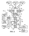
- Figure 2 shows GPS antenna 3 to receive ephemerides from satellite 110, satellite 111 and satellite 112 as shown by arrows 113-115.
- Antenna 3 receives ephemerides on two separate frequencies so as to obtain two sets of signals or "channels.”
- One set of signals is transmitted to low noise amplifier 5 as illustrated by arrow 117 and the other set of signals is transmitted to low noise amplifier 6 as shown by arrow 118.
- Electrical signals are amplified by low noise amplifier 5 and the resulting signal is transmitted to GPS radio frequency circuit board 22 as shown by arrow 119.
- low noise amplifier 6 amplifies the incoming signals and transmits them to GPS radio frequency circuit board 22 as indicated by arrow 120.
- GPS radio frequency circuit board 22 contains radio reception and transmission circuitry which then transmits the signals as shown by arrow 121 to digital circuit board 23.
- Digital circuit board 23 contains logic for processing GPS ephemerides and correction information so as to determine the exact position of the GPS system.
- Radio antenna 10 receives radio broadcasts as illustrated by arrow 128 which contains DGPS error correction information from radio relay 700 which is transmitted to radio circuit board 25, as shown by arrow 126. However, error correction information may be received from any of a number of other sources.
- Radio circuit board 25 includes electronic circuits for broadcasting and receiving radio signals. Radio circuit board 25 processes the signal and transmits the signal to digital circuit board 23 as shown by arrow 131.
- error correction data includes calculated pseudoranges.
- error correction data includes carrier phase data and pseudoranges. The position may then be displayed on display unit 900.
- digital circuit board 23 determines the correction information using known location information.
- the known location information may be input using display unit 900.
- the correction information is then sent, as shown by arrow 132 to radio circuit board 25 (connectors attached to power and I/O circuit board 24 route the signal directly).
- Radio circuit board 25 then broadcasts the correction information through radio antenna 10 as shown by arrow 127. Radio signals are sent and received at a frequency of 2.44 GigaHertz. However, any of a number of other frequencies could be used.
- power I/O circuit board 24 contains electronic circuitry for power management and transfer functions and regulates power to other components.
- Power I/O circuit board 24 is coupled to battery 41 as shown by arrow 145 and provides power and power management functions for the electronic components GPS unit 101.
- Power I/O circuit board is directly coupled to radio circuit board 25 and digital circuit board 23 as shown by arrows 124.
- An on/off switch on display panel 200 is connected to power I/O circuit board as shown by arrow 129 such that, by engaging the on/off switch, the GPS unit may be turned on and off.
- Input and output to external devices is coupled through I/O ports 13-15 as shown by box 140 and arrows 141 and 142.
- Display unit 900 is coupled to GPS unit 101 through I/O ports 13-15 as shown by arrows 143-144.
- FIG. 3 shows GPS antenna 3 to be mounted onto ground plane 2.
- Ground plane 2 lies over low noise amplifier housing 4 and is enclosed by radome 1.
- Low noise amplifier housing 4 fits into housing 12.
- Upper magnesium housing 8 is secured by flexible bumper 7 to low noise amplifier housing 4.
- Insulating ring 282 fills the space between bumper ring 18 and low noise amplifier housing 4 and absorbs shock from bumper ring 18.
- Bumper 19 is molded to bumper ring 18 and is a soft plastic material for absorbing shock and vibration.
- GPS antenna 3 is coupled to low noise amplifier 5 by semi-rigid coaxial cable 16 which couples to connector 250.
- Connector 250 couples to receptacle 216 which is attached to low noise amplifier 5.
- semi-rigid coaxial cable 17 extends from GPS antenna 3 to connector 251.
- Connector 251 mates with receptacle 217 which is attached to low noise amplifier 6.
- Low noise amplifier 5 and low noise amplifier 6 are small circuit boards which attached to low noise amplifier housing 4 and which amplify portions of the GPS signal separately.
- Low noise amplifier housing 4 is formed of plastic and the bottom side of low noise amplifier housing 4 is coated with copper to create an electromagnetic interference (EMI) and radio frequency interference(RFI) enclosure so as to shield EMI and RFI emissions from and to low noise amplifiers 5-6.
- Connector 214 attaches tu the bottom of low noise amplitier 5 and couples cable 212 to bulkhead connector 210.
- Bulkhead connector 210 engages a connector receptacle on GPS radio frequency circuit board 22 so as to electrically connect low noise amplifier 5 to GPS radio frequency circuit board 22.
- Connector 215 attaches to a connector receptacle attached to the bottom of low noise amplifier 6 and couples cable 213 to bulkhead connector 211.
- Bulkhead connector 211 engages a connector receptacle on GPS radio frequency circuit board 22 so as to electrically connect low noise amplifier 5 to GPS radio frequency circuit board 22.
- antenna 10 includes a parallel feed network which feeds patch antennas 44-51 (46-51 are not shown).
- Flexible bumper 11 supports lower magnesium housing 9 which mates with upper magnesium housing 8 so as to enclose digital circuit board 23, power I/O circuit board 24, radio circuit board 25, GPS radio frequency circuit board 22 and ring 21.
- Lower magnesium housing 8 and upper magnesium housing 9 are made of a magnesium which shields RFI and EMI emissions. In order to decrease weight, lower magnesium housing 9 and upper magnesium housing 8 do not completely enclose the top and bottom of the enclosure which they form.
- Metallic cloth 272 is attached, using adhesive to lower magnesium housing 9 and metallic cloth 271 is attached, using adhesive strips to upper magnesium housing 8.
- Metallic cloth strip 270 attaches to both lower magnesium housing 9 and upper magnesium housing 10 so as to form the sides of the enclosure.
- Metallic cloth 271 and metallic cloth 272 and metallic cloth strip 270 may be made of a metallic cloth such as a nickel plated polyester.
- Connector 26 which mates with a connector receptacle located on power I/O circuit board 24 connects the circuit boards 22-25 to I/O port 13 (not shown), I/O port 14, and I/O port 15 (not shown), display panel 200 and power source coupling 55 through cable 40.
- Antenna 10 includes a connector receptacle which directly couples to connector 280 which mates with a connector receptacle located on radio circuit board 25 so as to connect radio circuit board 25 with antenna 10.
- Power source coupling 55 electrically connects with battery 1 to provide power to GPS unit 101. Provision for connectivity of additional components and units is obtained by I/O ports 13-15 which allow for additional components to be coupled to the GPS system such as display and input units and alternate power sources.
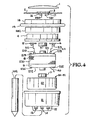
- FIG. 4 shows housing 12 to include openings into which connector receptacles are disposed so as to form I/O ports 13-15.
- Antenna 10 includes an omnidirectional parallel fed array of patch antennas 44-51. It can be seen that lower magnesium housing 9 fits within bumper 11 and upper magnesium housing 8 fits within bumper 7 so as to shield the electronics within the enclosure formed by lower magnesium housing 9, upper magnesium housing 8, and magnetic cloth 270-272 from shock and vibration.
- Bumper ring 18 which is connected to bumper 19 dampens shock to GPS unit 101. Bumper 19 and bumper ring 18 are particularly effective when GPS unit 101 is dropped as bumper 19 is likely to be the first part of GPS unit 101 to strike the ground.
- Insulating ring 282 is made of a closed cell elastomeric foam such as Poron.
- Figure 5 shows power I/O circuit board 24 and digital circuit board 23 and radio circuit board 25 and GPS radio frequency board 22 to be located between upper magnesium housing 8 and lower magnesium housing 9.
- Connector 26 which is electrically coupled to cable 40 connects directly to a connector receptacle attached to power I/O circuit board 24.
- Connector 283 mates with a corresponding connector receptacles so as to electrically connect GPS radio frequency circuit board 22 to digital circuit board 23.
- Connector 284 mates with a corresponding connector receptacles so as to electrically connect power I/O circuit board 24 to digital circuit board 23.
- Connector 285 mates with a corresponding connector receptacles so as to electrically connect radio circuit board 25 to power I/O circuit board 24.
- Bolts 219 engage openings 291 in upper magnesium housing 8 and pass through openings in spacers 60 and through threaded openings in bottom magnesium housing so as to secure circuit boards 22-25 within upper magnesium housing 8 and lower magnesium housing 9.
- Nuts 225 engage each of screws 219.
- Ring 21 to which polyester sheet 20 is attached supports GPS radio frequency circuit board 22 on top of polyester sheet 20 so as to separate GPS radio frequency circuit board 22 from the other circuit boards 23-25 so as to limit interference from EMI from radio frequency circuit board 25 and power I/O circuit board 24.
- Spacers 60 which may be stainless steel PEM spacers support and separate circuit boards 22-25.
- FIG 6 shows a second embodiment which includes a tripod base 502.
- GPS unit 101 is identical to GPS unit 101 shown in the first embodiment and illustrated in Figures 1-5.
- Tripod base 502 is interchangeable with pole 102 shown in the first embodiment and it attaches to housing 12 in the same manner as does pole 102 of the first embodiment.
- Tripod 502 includes top section 504 to which leg 505, leg 506 and leg 507 are attached.
- Finder 510 allows GPS unit 101 to be precisely located over a landmark.
- Finder 510 may be a prismatic optical finder, a laser optical finder, a fixed height tripod, a laser finder with a fourth leg, or any of a number of other known location devices which are commonly used in construction and surveying equipment.
- Battery 41 is located within tripod 502.
- battery 41 is shown to be located within top section 504 of tripod 502, battery 41 could be located in or on any of legs 505-507. In fact, it may be desirable to locate battery 41 in legs 505-507 depending on the type of location equipment used as finder 510.
- Finder 510 could be used to precisely locate tripod 502 over a USGS marker such that the GPS unit would be able to function as a reference site such that the location of other GPS devices may be accurately determined by using DGPS techniques.
- the location and differential correction data may be monitored on display 901 of display unit 900. Since display unit 900 is a separate unit it may be connected and disconnected as needed.
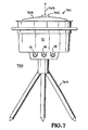
- Radio relay system 700 incorporates many of the components disclosed in the first and second embodiments as shown in Figures 1-6.
- Radio relay system 700 includes radio relay unit 701 which is mounted on tripod 760.
- Radio relay unit 701 includes housing top 704 which has a circular opening into which removable transceiver unit 702 fits.
- Removable transceiver antenna 703 attaches to removable transceiver unit 702.
- Removable transceiver unit 702 can be easily removed from housing top 704.
- radio relay 701 operates at the 2.44 GigaHertz frequency.
- radio relay unit 701 This allows for radio relay unit 701 to operate at any of a number of desired frequencies by simply inserting a removable transceiver unit 702 which operates at the desired frequency.
- Housing 12 and I/O ports 13-15 are identical to housing 12 and I/O ports 13-15 shown in the first and second embodiments.
- radio relay unit 701 is shown to be mounted onto tripod 760, radio relay unit 701 could be either attached to a pole such as pole 102 shown in the first embodiment or attached to a tripod such as tripod 502 shown in the second embodiment.
- radio relay unit 701 may be set on top of some structure or set on the ground and a power source may be attached to one of I/O ports 13-15.
- Radio relay system 700 to include radio antenna 10 which receives radio broadcasts from sources broadcasting at its frequency and transmits on the same frequency.
- Radio antenna 10 may receive signals from a GPS unit such as GPS unit 780 which may be located over a landmark having a known location. Signals received by radio antenna 10 such as signals from GPS unit 780, shown by arrow 793, are transmitted to radio circuit board 25 as shown by arrow 781. Radio circuit board 25 demodulates the signals and transmits the signals to power I/O and digital circuit board 800 as shown by arrow 799.
- the signals are transmitted to removable transceiver unit 702 as shown by arrow 782.
- Removable transceiver unit 702 broadcasts the signals at a higher frequency through removable transceiver unit antenna 703 as shown by arrow 783. This high frequency signal may be received by other radio relay systems such as radio relay system 790, as shown by arrow 788.
- radio relay system 700 operates as a relay at the frequency at which radio circuit board 25 and antenna 10 broadcast and receive.
- Display panel 200 includes an on/off switch which is coupled to power I/O and digital circuit board 800 as shown by arrows 785 and 786.
- Display panel 200 includes a number of lighted indicators which indicate the status and operation of relay system 700. Power is provided to radio relay system 700 by power source 801 as indicated by arrow 787. Power I/O and digital circuit board 800 also connects to I/O ports 13-15, as illustrated by arrows 794-795 and box 797, to which separate display units and input devices may be attached.
- radio relay system 700 also operates by receiving signals at the frequency at which removable transceiver unit 702 operates.
- signals may originate from other radio relay systems such as radio relay system 790 as shown by arrow 784.
- These signals are received by removable transceiver unit antenna 703 and are transmitted to removable transceiver unit 702 as shown by arrow 789.
- Removable transceiver unit 702 transmits the signals to power I/O and digital circuit board 800 as shown by arrow 791 which transmits the signals to radio circuit board 25 as shown by arrow 798 which broadcasts the signals through radio antenna 10 as shown by arrow 796.
- the resulting radio broadcast may be received by GPS unit 780 as shown by arrow 792.
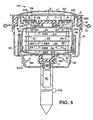
- Figure 9 shows removable transceiver unit 702 to fit within receptacle opening 711 of housing top 704.
- Flexible bumper 7 is mounted above upper magnesium housing 8 and flexible bumper 11 is mounted below lower magnesium housing 9 so as to securely hold upper magnesium housing 8 and lower magnesium housing 9 within housing 12.
- Flexible bumper 7 and flexible bumper 11 absorb shock and vibration so as to protect the electronics located within upper magnesium housing 8 and lower magnesium housing 9.
- Flexible bumper 7, flexible bumper 11, lower magnesium housing 9 and upper magnesium housing 8 are identical to flexible bumper 7, flexible bumper 11, lower magnesium housing 9 and upper magnesium housing 8 shown in the first and second embodiments.
- housing 12 identical to housing 12 shown in the first two embodiments.
- metallic cloth 271-272 and metallic cloth strip 270 are identical to metallic cloth strip 270 and metallic cloth 271-272 shown in the first two embodiments.
- Power source 41 is identical to power source 41 shown in the first two embodiments and display panel 200 is identical to display panel 200 shown in the first two embodiments.
- I/O ports 13-15 are identical to I/O ports 13-15 shown in the first two embodiments of the present invention and they allow for coupling input and output between radio relay system 700 and other devices.
- Radio relay unit 701 is supported by tripod 760 which connects to radio relay unit 701 via screw threads 761. Power source 41 fits within tripod 760.
- FIG 10 shows removable radio transceiver unit 702 to fit within opening 711 in housing top 704.
- Removable radio transceiver unit 702 includes connector 740 which mates with connector receptacle 730.
- Connector receptacle 730 is coupled to power I/O and digital circuit board 800 by cable 751.
- Power I/O and digital circuit board 800 is coupled to connector receptacles in I/O ports 13-15 (connector receptacles for I/O ports 13,15 are not shown), to display/control panel 200, and to power source coupling 55.
- Power I/O and digital circuit board 800 couples to radio circuit board 25 via connector 810.
- Radio circuit board 25 is coupled to antenna 10 which includes a parallel feed network and antennas 44-51 (46-51 are not shown) via receptacle 80 which is secured to antenna 10.
- Power source coupling 55 is identical to power source coupling 55 shown in the first and second embodiments and allows power to be coupled from battery 41 to power I/O and digital circuit board 800.
- Battery 41 is contained within tripod 760.
- Tripod 760 is identical to tripod 502 shown in the second embodiment of the present invention except that tripod 760 does not include finder 510.
- Cable 40 connects power source coupling 55, display board 200, and I/O ports 13-15 to power I/O and digital circuit board 800.
- Radio transceiver 702 operates at 900 MegaHertz. However, any of a number of different frequencies may be used.
- Different frequencies may be easily obtained by using removable transceiver units operating at various different frequencies and inserting removable transceiver units operating at the desired frequency as dictated by the situation.
- a repeater operating at a different frequency may be easily obtained by replacing transceiver 800 with a transceiver operating at the desired frequency.
- Signals to and from antenna 10 are broadcast at 2.44 GigaHertz, however any of a number of other frequencies could also be used.
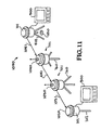
- GPS system 1050 which includes GPS unit 101 is located over a known location 1010 such as a USGS survey site.
- Tripod 502 includes an optical location finder which is used to precisely locate GPS system 1050 over the known location 1010.
- Correction information are broadcast from GPS system 1050, as shown by arrow 1051 are received by radio relay 1040 at a frequency of 2.44 GigaHertz.
- Radio relay 1040 relays the signals to radio relay 1030 at 900 MegaHertz as shown by arrow 1041.
- the signals received by relay 1030 are then transmitted at 2.44 GigaHertz to GPS system 1020 as shown by arrow 1031.
- GPS system 1020 includes GPS unit 101 and pole 102.
- the location of GPS system 1020 may be accurately determined.
- display unit 900 Connected to GPS unit 101 of GPS system 1020 is display unit 900 which can be used to monitor the position of GPS system 1020 in order to exactly locate a desired position. Since radio relay 1020 and radio relay 1030 may also operate at 2.44 GigaHertz, a single radio relay, or both radio relay 1030 and radio relay 1040 could be used and operated at the 2.44 GigaHertz frequency, depending on the requirements of the particular location.
- GPS unit 1050 of Figure 11 could be receive only.
- a smaller, more simply designed radio antenna may be used and simplified radio processing circuitry could be used.
- a simple dipole antenna may be used in place of the complex structure of antenna 10.
- separate radio antennas may be used for transmitting and receiving, depending on the needs of the particular location. Radios may transmit and/or receive at any of a number of frequencies. In one embodiment, radios operate at frequencies allowed by, and under the requirements of Federal Communication Commission Part 9 and Part 2 regulations.
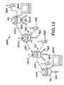
- one or more of I/O ports 13-15 are adapted for connection to an external radio such as external radios 1201-1204 of Figure 12.
- the operating characteristics of external radios 1201-1204 are selected to fit the needs of the particular operating situation. For example, in different countries and in different regions of the US, communication is at different power levels and at different frequencies. Thus, a radio transmitting at, receiving at, or transmitting and receiving at a desired frequency and at a desired power level may be used as required by the particular situation.
- multiple external radios may be coupled to I/O ports of the GPS unit which operate at different frequencies as required by the location. For example, one radio may be used to receive signals and a second radio may be used for transmission.
- External radios may also be coupled to the I/O ports of radio relay systems.
- External radio 1202 of Figure 12 is shown to be coupled to radio relay system 1030 and external radio 1203 is shown to be coupled to radio relay system 1040.
- the external radio may be used in conjunction with a removable transceiver unit such as removable transceiver unit 702 of Figure 7 or may be used without a removable transceiver unit.
- the external radio may be used in conjunction with a radio transmission and receiving unit such as the system including antenna 10 and radio circuit board 25, or may be used without an internal radio transmitter, receiver or transmitting and receiving system.
- external radio 1201-1204 are radio data transmitters which (also referred to as a radio modem) transmits data in serial form digitally through I/O ports such as I/O ports 13-15 of Figure 4.
- external radio 1201-1204 are two way radios such as model number RFM96W manufactured by Pacific Crest of Santa Clara, California.
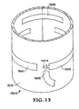
- a slotted antenna such as slotted antenna 1300 of Figure 13 is used to transmit in an toroidal pattern. Slotted antenna 1300 could also be used to receive radio signals. Alternatively a separate antenna may be used for receiving radio signals and slotted antenna 1300 may be used exclusively for transmitting radio signals. In one embodiment, slotted antenna 1300 operates at a frequency of 450 MegaHertz. The use of slotted antenna 1300 allows for operation at higher frequencies and provides an omnidirectional broadcast pattern. In one embodiment, slotted antenna is used in place of antenna 10 in some or all of the embodiments shown in Figures 1-11. Slotted antenna 1300 is shown to include slots 1301-1303 which extend around antenna strip 1310. In one embodiment, antenna strip 1310 is copper and slot 1302 is directly driven by antenna cable 1305 which couples power to slot 1302 at launching section 1304. Antenna slots 1302 and 1303 are parasitically driven as current moves through copper antenna strip 1310.
- the antenna radiation pattern is herein described with reference to a toroidal shape.
- Other characteristics of the radiation pattern include the fact that the antenna radiates throughout a azimuthal axis of 360 degrees and the radiation strength is relatively constant throughout the entire 360 degree azimuth.
- the amplitude of the resulting signal is constant throughout a 360 degree azimuth extending horizontally from the antenna.
- the resulting signal exhibits a signal which is constant around a 360 degree azimuth for each angle extending along a vertical axis up from a center horizontal axis representing 0 degrees vertically from the antenna up to a vertical angle of 45 to 50 degrees and downward to a vertical angle of about 45 to 50 degrees.
- the resulting signal drops off to 0 at an angle of 90 degrees both above and below the center horizontal axis.
- the resulting radiation pattern is substantially constant in the horizontal plane for any azimuthal angle.
- the resulting antenna may also be described as having a relatively constant pattern azimuthally in planes running perpendicularly through the central axis.
- antenna strip 1310 has a height of 3.25 inches and a length of 22 inches is used as an antenna and slot 1301 has a height of.7 inches and a length of 7.75 inches, and slot 1302 has a height of .7 inches and a length of 11 inches and launching section 1304 has a height of .4 inches and a length of 1.5 inches and is powered .8 inches from its closed end such that slots 1301 and slot 1302 are separated by a distance of 6.25 inches.
- slot 1303 has a length of 8.6 inches and a height of .35 inches.
- antenna 1300 radiates at a frequency of 450 MegaHertz. Slotted antenna 1300 may also be designed to operate at different frequencies as required. In one embodiment slotted antenna 1300 operates at a frequency of 900 MegaHertz.
Landscapes
- Engineering & Computer Science (AREA)
- Radar, Positioning & Navigation (AREA)
- Remote Sensing (AREA)
- Physics & Mathematics (AREA)
- General Physics & Mathematics (AREA)
- Computer Networks & Wireless Communication (AREA)
- Signal Processing (AREA)
- Position Fixing By Use Of Radio Waves (AREA)
- Radio Relay Systems (AREA)
- Radar Systems Or Details Thereof (AREA)
- Mobile Radio Communication Systems (AREA)
Claims (21)
- Un système comprenant:un boítier (12);un récepteur (22) disposé à l'intérieur dudit boítier (12) pour recevoir des signaux de détermination de position en provenance de satellites (110, 111, 112);une antenne réceptrice (3) disposée à l'intérieur d'un radome (1), ladite antenne réceptrice (3) étant couplée audit récepteur (2) et prévue pour recevoir des signaux en provenance des satellites;un premier système radio (25) comprenant une antenne (10) disposée à l'intérieur dudit boítier (12) pour recevoir des données en provenance de systèmes de détermination de position de tierces parties;un ensemble de circuits de traitement de signaux de position (23) disposé à l'intérieur dudit boítier (12) et adapté pour analyser lesdits signaux de détection de position de manière ainsi à déterminer la position dudit boítier (12); etun ensemble de circuits de traitement de signaux radio (25) adapté pour démoduler les signaux radio reçus des systèmes de détermination de position de tierces parties et les fournir audit ensemble de circuits de traitement de signaux de position (23) de manière à déterminer de façon précise la position dudit boítier (12); ledit système étant caractérisé par le fait que:ledit radome (1) et ladite antenne réceptrice (3) sont adaptés pour être retirés et remplacés par un dessus de boítier (704) présentant une disposition pour le montage d'un second système radio (702) à l'intérieur; et queledit ensemble de circuits de traitement de signaux de position (23) est adapté pour être retiré et remplacé par ledit second système radio(702), où, lors du remplacement dudit ensemble de circuits de traitement de signaux de position (23) par ledit second système radio (702), ledit système est adapté pour relayer les signaux radio reçus à partir d'autres systèmes de détermination de position.
- Le système de la revendication 1 dans lequel ladite antenne (10) est une antenne fendue (1300), ladite antenne fendue (1300) ayant une bande d'antenne (1310) qui est disposée de manière circulaire, ladite bande d'antenne (1310) présentant des fentes (1301-1303) disposées à l'intérieur de telle manière que ladite antenne fendue (1300) rayonne dans un motif toroïdal.
- Le système de la revendication 1 ou 2 dans lequel ledit système radio (25) peut émettre de telle manière que des données de correction puissent être émises vers des systèmes de détermination de position de tierces parties.
- Le système de l'une quelconque des revendications précédentes dans lequel:l'ensemble de circuits de traitement de signaux de position (23) disposé à l'intérieur dudit boítier (12) et adapté pour analyser les signaux de détermination de position est prévu pour résoudre un algorithme de phase porteuse permettant de déterminer la position et de déterminer des données de correction pour une détermination de position cinématique en temps réel; etl'ensemble de circuits de traitement de signaux radio (25) est adapté afin de diffuser lesdites données de correction pour une détermination de position cinématique en temps réel vers d'autres systèmes de détermination de position.
- Le système de l'une quelconque des revendications précédentes dans lequel ledit ensemble de circuits de traitement de signaux de position (23) et ledit ensemble de circuits de traitement de signaux radio (25) comprennent en outre:un premier circuit imprimé (24) qui effectue des fonctions de transfert et de gestion d'énergie et des fonctions d'entrée et sortie;un second circuit imprimé (25) qui effectue des fonctions de réception et d'émission radio; etun troisième circuit imprimé (22) qui analyse des signaux reçus à partir de satellites.
- Le système de l'une quelconque des revendications précédentes comprenant en outre une pluralité de réceptacles à connecteur (13-15) disposés à l'intérieur dudit boítier (12) pour relier, audit système de détermination de position intégré, d'autres dispositifs ou éléments constitutifs.
- Le système de la revendication 6 comprenant en outre:un système radio externe (1201), ledit système radio externe (1201) étant couplé à l'un de ladite pluralité de réceptacles à connecteur (13-15) pour recevoir des signaux radio et couplant lesdits signaux radio reçus audit ensemble de circuits de traitement de signaux de position (23).
- Le système de la revendication 5 comprenant en outre:un boítier interne (8, 9) disposé à l'intérieur dudit boítier (12) pour protéger, des interférences électriques et magnétiques, ledit premier circuit imprimé (24), ledit second circuit imprimé (25) et ledit troisième circuit imprimé (22).
- Le système de l'une quelconque des revendications précédentes comprenant en outre:un chercheur de position optique (510) relié audit système de telle manière que ledit boítier (12) puisse être positionné de manière précise sur un emplacement spécifique.
- Le système de l'une quelconque des revendications précédentes comprenant en outre:un amplificateur à faible bruit (5) relié audit récepteur.
- Le système de l'une quelconque des revendications précédentes comprenant en outre:un boítier d'amplificateur à faible bruit (4) relié audit boítier (12) sur lequel est monté au moins un amplificateur à faible bruit (5, 6).
- Le système de la revendication 11 dans lequel ledit boítier d'amplificateur à faible bruit (4) peut être retiré en même temps que ledit radome (1) dudit boítier (12) et être remplacé par un dessus de boítier (704) tel que ledit second système radio (702) puisse être placé dans ledit dessus de boítier (704) de manière à recevoir et à relayer des signaux radio.
- Le système de l'une quelconque des revendications précédentes dans lequel ladite antenne radio (10) comprend une antenne de connexion (44-51).
- Le système de la revendication 2 dans lequel ladite antenne fendue (1300) fonctionne à une fréquence de 450 MégaHertz.
- Le système de la revendication 2 dans lequel ladite antenne fendue (1300) diffuse à une fréquence de 900 MégaHertz.
- Le système de l'une quelconque des revendications précédentes comprenant en outre:des réceptacles (13-15) pour coupler, audit système, des dispositifs externes; etun système radio externe (1201) comprenant un mécanisme de liaison adapté pour coupler auxdits réceptacles (13-15) de telle manière que .ledit système radio externe (1201) puisse être couplé auxdits réceptacles (13-15) afin que des signaux radio puissent être couplés entre ledit système radio externe (1201) et ledit ensemble de circuits de traitement de signaux de position (23) ou ledit circuit imprimé.
- Un réseau comprenant:un premier boítier (101) comprenant une disposition pour la fixation à celui-ci d'un chercheur de localisation optique (510) pour localiser de manière précise ledit premier boítier (101) sur un point de référence connu (1010);un premier système de détermination de position comprenant une antenne et un récepteur, ledit premier système de détermination étant monté à l'intérieur dudit premier boítier (101) pour recevoir des signaux de détermination de position en provenance de satellites;une première antenne radio montée à l'intérieur dudit premier boítier (101) pour émettre et recevoir des signaux radio à une première fréquence radio;un premier circuit imprimé disposé à l'intérieur dudit premier boítier (101) et relié au récepteur dudit premier système de détermination de position et relié à ladite première antenne radio, ledit premier circuit imprimé étant adapté pour analyser des signaux de détermination de position et des signaux radio de manière à déterminer avec précision la position dudit premier boítier (101);un second boítier (1020);un second système de détermination de position comprenant une antenne et un récepteur, ledit second système de détermination de position étant monté à l'intérieur dudit second boítier (1020) pour recevoir des signaux de détermination de position en provenance de satellites;une seconde antenne radio montée à l'intérieur dudit second boítier (1020) pour émettre et recevoir des signaux radio à ladite première fréquence radio;un second circuit imprimé disposé à l'intérieur dudit second boítier (1020) et relié au récepteur dudit second système de détermination de position et relié à ladite seconde antenne radio, ledit second circuit imprimé étant adapté pour analyser des signaux de détermination de position et des signaux radio de manière à déterminer avec précision la position dudit second boítier (1020); etun système selon l'une quelconque des revendications 1-16, dans lequel ledit premier système radio dudit système reçoit et diffuse des signaux radio à ladite première fréquence radio, et dans lequel ledit second système radio reçoit et relaie des signaux radio à une seconde fréquence radio, le réseau étant un réseau de système de détermination de position intégré.
- Le réseau de la revendication 17 dans lequel ladite seconde fréquence radio est différente de ladite première fréquence radio.
- Le réseau de la revendication 17 dans lequel ladite première fréquence radio et ladite seconde fréquence radio sont égales l'une à l'autre.
- Le réseau de l'une quelconque des revendications 17-19 dans lequel ledit premier boítier (101) est identique audit second boítier (1020) et dans lequel ledit premier boítier (101) est identique audit boítier du système.
- Le réseau de l'une quelconque des revendications 17-20 comprenant en outre:un quatrième boítier (1040);un quatrième circuit imprimé disposé à l'intérieur dudit quatrième boítier (1040);un second dessus de boítier fixé audit quatrième boítier (1040) de manière à entourer ledit quatrième circuit imprimé à l'intérieur dudit quatrième boítier (1040);un quatrième système radio disposé à l'intérieur dudit quatrième boítier (1040) et relié audit quatrième circuit intégré pour recevoir et rediffuser des signaux radio à une première fréquence radio; etun second système radio amovible disposé à l'intérieur dudit second dessus de boítier et relié audit quatrième circuit imprimé de telle manière que des signaux radio puissent être reçus et relayés entre ledit premier système radio amovible et ledit second système radio amovible à ladite seconde fréquence radio.
Applications Claiming Priority (2)
| Application Number | Priority Date | Filing Date | Title |
|---|---|---|---|
| US918628 | 1997-08-22 | ||
| US08/918,628 US6091358A (en) | 1997-01-31 | 1997-08-22 | Integrated position determination system with radio relay |
Publications (3)
| Publication Number | Publication Date |
|---|---|
| EP0903589A2 EP0903589A2 (fr) | 1999-03-24 |
| EP0903589A3 EP0903589A3 (fr) | 2000-02-23 |
| EP0903589B1 true EP0903589B1 (fr) | 2004-11-24 |
Family
ID=25440694
Family Applications (1)
| Application Number | Title | Priority Date | Filing Date |
|---|---|---|---|
| EP98306726A Expired - Lifetime EP0903589B1 (fr) | 1997-08-22 | 1998-08-21 | Système de détermination de position intégré avec liaison hertzienne |
Country Status (4)
| Country | Link |
|---|---|
| US (1) | US6091358A (fr) |
| EP (1) | EP0903589B1 (fr) |
| AT (1) | ATE283495T1 (fr) |
| DE (1) | DE69827730T2 (fr) |
Cited By (13)
| Publication number | Priority date | Publication date | Assignee | Title |
|---|---|---|---|---|
| DE102005006389A1 (de) * | 2005-02-11 | 2006-08-24 | Thomas Muhr | Verfahren zur Positionsbestimmung eines mobilen Objekts, insbesondere einer landwirtschaftlichen Arbeitsmaschine |
| WO2007010048A1 (fr) * | 2005-07-22 | 2007-01-25 | Pole Star | Equipement mobile, procede et systeme de positionnement d'un equipement mobile |
| US7612716B2 (en) | 1999-03-05 | 2009-11-03 | Era Systems Corporation | Correlation of flight track data with other data sources |
| US7667647B2 (en) | 1999-03-05 | 2010-02-23 | Era Systems Corporation | Extension of aircraft tracking and positive identification from movement areas into non-movement areas |
| US7739167B2 (en) | 1999-03-05 | 2010-06-15 | Era Systems Corporation | Automated management of airport revenues |
| US7777675B2 (en) | 1999-03-05 | 2010-08-17 | Era Systems Corporation | Deployable passive broadband aircraft tracking |
| US7782256B2 (en) | 1999-03-05 | 2010-08-24 | Era Systems Corporation | Enhanced passive coherent location techniques to track and identify UAVs, UCAVs, MAVs, and other objects |
| US7889133B2 (en) | 1999-03-05 | 2011-02-15 | Itt Manufacturing Enterprises, Inc. | Multilateration enhancements for noise and operations management |
| US7908077B2 (en) | 2003-06-10 | 2011-03-15 | Itt Manufacturing Enterprises, Inc. | Land use compatibility planning software |
| US7965227B2 (en) | 2006-05-08 | 2011-06-21 | Era Systems, Inc. | Aircraft tracking using low cost tagging as a discriminator |
| US8072382B2 (en) | 1999-03-05 | 2011-12-06 | Sra International, Inc. | Method and apparatus for ADS-B validation, active and passive multilateration, and elliptical surveillance |
| US8203486B1 (en) | 1999-03-05 | 2012-06-19 | Omnipol A.S. | Transmitter independent techniques to extend the performance of passive coherent location |
| US8446321B2 (en) | 1999-03-05 | 2013-05-21 | Omnipol A.S. | Deployable intelligence and tracking system for homeland security and search and rescue |
Families Citing this family (35)
| Publication number | Priority date | Publication date | Assignee | Title |
|---|---|---|---|---|
| US6560461B1 (en) | 1997-08-04 | 2003-05-06 | Mundi Fomukong | Authorized location reporting paging system |
| US6297969B1 (en) * | 1999-08-10 | 2001-10-02 | Lucent Technologies Inc. | Electromagnetic interference shielding enclosure |
| US6522291B1 (en) * | 1999-12-10 | 2003-02-18 | Matsushita Electric Works, Ltd. | GPS receiver sharing an antenna ground plane with an EMI shield |
| GB0012641D0 (en) * | 2000-05-25 | 2000-07-12 | Koninkl Philips Electronics Nv | A method of estimating the location of a device |
| GB0014719D0 (en) | 2000-06-16 | 2000-08-09 | Koninkl Philips Electronics Nv | A method of providing an estimate of a location |
| US8175799B1 (en) * | 2002-10-15 | 2012-05-08 | Douglas Edward Woehler | Location system |
| US7129900B2 (en) * | 2003-09-08 | 2006-10-31 | Tantalus Systems Corp. | Meter antenna |
| US20050253752A1 (en) * | 2004-05-13 | 2005-11-17 | Bushnell Performance Optics | Apparatus and method for allowing user to track path of travel over extended period of time |
| US7123189B2 (en) * | 2004-05-13 | 2006-10-17 | Bushnell Performance Optics | Apparatus and method for allowing user to track path of travel over extended period of time |
| US7342360B2 (en) * | 2004-10-20 | 2008-03-11 | The Stanley Works | Flashlight |
| US7812782B2 (en) * | 2007-02-07 | 2010-10-12 | Caterpillar Trimble Control Technologies Llc | Radome |
| EP2000819A1 (fr) * | 2007-06-04 | 2008-12-10 | Leica Geosystems AG | Combinaison d'antennes pour une station GNSS mobile et station GNSS mobile |
| US9103912B2 (en) | 2008-12-31 | 2015-08-11 | Javad Gnss, Inc. | Inter-channel bias calibration for navigation satellite systems |
| US8022868B2 (en) * | 2008-12-31 | 2011-09-20 | Javad Gnss, Inc. | Inter-channel bias calibration for navigation satellite systems |
| US8169379B2 (en) * | 2009-02-13 | 2012-05-01 | Javad Gnss, Inc. | Portable multiband antenna |
| US9086477B2 (en) | 2012-06-06 | 2015-07-21 | Novatel Inc. | Anti-jamming subsystem employing an antenna array with a horizontal circular reception pattern |
| US20140125520A1 (en) * | 2012-06-22 | 2014-05-08 | Patrick C. Fenton | Anti-jamming subsystem employing an antenna with a horizontal reception pattern |
| US9383448B2 (en) | 2012-07-05 | 2016-07-05 | Deca System Co., Ltd. | Golf GPS device with automatic hole recognition and playing hole selection |
| US9998863B2 (en) | 2013-08-19 | 2018-06-12 | Estimote Polska Sp. Z O. O. | System and method for providing content using beacon systems |
| US10244348B2 (en) | 2013-08-19 | 2019-03-26 | Estimote Polska Sp z o.o. | Methods for authenticating communication between a mobile device and wireless beacon at a remote domain name system, projecting a level of interest in a nearby product, and providing and ordering option or product data |
| CN103487818A (zh) * | 2013-09-25 | 2014-01-01 | 上海旦迪电子科技有限公司 | 北斗卫星导航智能接收器 |
| USD725509S1 (en) * | 2014-03-07 | 2015-03-31 | Zircon Corporation | Surface tool |
| USD726559S1 (en) * | 2014-03-07 | 2015-04-14 | Zircon Corporation | Surface tool |
| US10871577B2 (en) * | 2015-03-24 | 2020-12-22 | Panasonic Intellectual Property Management Co., Ltd. | Positioning method, positioning system, correction information generation method, correction information generation device, and positioning system relay station and terminal |
| WO2017040690A1 (fr) | 2015-09-02 | 2017-03-09 | Estimote, Inc. | Système et procédés de suivi d'objet avec des balises sans fil |
| US10136250B2 (en) | 2015-09-02 | 2018-11-20 | Estimote Polska Sp. Z O. O. | System and method for lower power data routing |
| US9826351B2 (en) | 2015-09-02 | 2017-11-21 | Estimote Polska Sp. Z O. O. | System and method for beacon fleet management |
| WO2017143281A1 (fr) * | 2016-02-17 | 2017-08-24 | Estimote, Inc. | Système et procédé de fourniture de contenu à l'aide de systèmes de balise |
| US9872146B2 (en) | 2016-03-22 | 2018-01-16 | Estimote Polska Sp. Z O. O. | System and method for multi-beacon interaction and management |
| WO2018009878A1 (fr) | 2016-07-07 | 2018-01-11 | Estimote Polska Sp. Z O. O. | Procédé et système destinés à la distribution de contenu avec une balise |
| WO2020039252A1 (fr) | 2018-08-22 | 2020-02-27 | Estimote Polska Sp Z.O.O. | Système et procédé pour vérifier la sécurité d'un dispositif |
| EP3841765A2 (fr) | 2018-08-24 | 2021-06-30 | Estimote Polska Sp. Z O.O. | Procédé et système de gestion d'actifs |
| CN110426722A (zh) * | 2019-06-20 | 2019-11-08 | 广州南方卫星导航仪器有限公司 | 移动站及差分修正数据的传输方法、终端设备、存储介质 |
| CN110850451A (zh) * | 2019-11-27 | 2020-02-28 | 宁波尼兰德磁业股份有限公司 | 太阳能gps跟踪器工具盒套装 |
| US11510326B2 (en) * | 2020-05-21 | 2022-11-22 | Utto Inc. | Mobile device retainer for field mapping and data collection |
Family Cites Families (9)
| Publication number | Priority date | Publication date | Assignee | Title |
|---|---|---|---|---|
| CH677154A5 (fr) * | 1988-07-06 | 1991-04-15 | Wild Leitz Ag | |
| US5467290A (en) * | 1993-08-18 | 1995-11-14 | Atlantic Richfield Company | Survey system and method |
| US5434789A (en) * | 1993-10-06 | 1995-07-18 | Fraker; William F. | GPS golf diagnostic system |
| JP3500524B2 (ja) * | 1993-12-16 | 2004-02-23 | マスプロ電工株式会社 | 移動体の衛星通信用アンテナ |
| US5589835A (en) * | 1994-12-20 | 1996-12-31 | Trimble Navigation Limited | Differential GPS receiver system linked by infrared signals |
| US5517199A (en) * | 1995-05-11 | 1996-05-14 | Aerodata Corporation | Emergency locator device |
| US5654717A (en) * | 1995-08-03 | 1997-08-05 | Trimble Navigation, Ltd. | GPS/radio antenna combination |
| US5734348A (en) * | 1995-08-31 | 1998-03-31 | Nikon Corporation | Surveying system using GPS |
| EP1223434B1 (fr) * | 1995-10-09 | 2010-08-25 | Snaptrack, Inc. | Système combiné de localisation GPS et de télécommunications utilisant un circuit partagé |
-
1997
- 1997-08-22 US US08/918,628 patent/US6091358A/en not_active Expired - Fee Related
-
1998
- 1998-08-21 AT AT98306726T patent/ATE283495T1/de not_active IP Right Cessation
- 1998-08-21 EP EP98306726A patent/EP0903589B1/fr not_active Expired - Lifetime
- 1998-08-21 DE DE69827730T patent/DE69827730T2/de not_active Expired - Fee Related
Cited By (14)
| Publication number | Priority date | Publication date | Assignee | Title |
|---|---|---|---|---|
| US7777675B2 (en) | 1999-03-05 | 2010-08-17 | Era Systems Corporation | Deployable passive broadband aircraft tracking |
| US8203486B1 (en) | 1999-03-05 | 2012-06-19 | Omnipol A.S. | Transmitter independent techniques to extend the performance of passive coherent location |
| US8446321B2 (en) | 1999-03-05 | 2013-05-21 | Omnipol A.S. | Deployable intelligence and tracking system for homeland security and search and rescue |
| US7612716B2 (en) | 1999-03-05 | 2009-11-03 | Era Systems Corporation | Correlation of flight track data with other data sources |
| US7667647B2 (en) | 1999-03-05 | 2010-02-23 | Era Systems Corporation | Extension of aircraft tracking and positive identification from movement areas into non-movement areas |
| US7739167B2 (en) | 1999-03-05 | 2010-06-15 | Era Systems Corporation | Automated management of airport revenues |
| US7889133B2 (en) | 1999-03-05 | 2011-02-15 | Itt Manufacturing Enterprises, Inc. | Multilateration enhancements for noise and operations management |
| US7782256B2 (en) | 1999-03-05 | 2010-08-24 | Era Systems Corporation | Enhanced passive coherent location techniques to track and identify UAVs, UCAVs, MAVs, and other objects |
| US8072382B2 (en) | 1999-03-05 | 2011-12-06 | Sra International, Inc. | Method and apparatus for ADS-B validation, active and passive multilateration, and elliptical surveillance |
| US7908077B2 (en) | 2003-06-10 | 2011-03-15 | Itt Manufacturing Enterprises, Inc. | Land use compatibility planning software |
| DE102005006389A1 (de) * | 2005-02-11 | 2006-08-24 | Thomas Muhr | Verfahren zur Positionsbestimmung eines mobilen Objekts, insbesondere einer landwirtschaftlichen Arbeitsmaschine |
| DE102005006389B4 (de) * | 2005-02-11 | 2009-05-20 | Thomas Muhr | Verfahren zur Positionsbestimmung eines mobilen Objekts, insbesondere einer landwirtschaftlichen Arbeitsmaschine |
| WO2007010048A1 (fr) * | 2005-07-22 | 2007-01-25 | Pole Star | Equipement mobile, procede et systeme de positionnement d'un equipement mobile |
| US7965227B2 (en) | 2006-05-08 | 2011-06-21 | Era Systems, Inc. | Aircraft tracking using low cost tagging as a discriminator |
Also Published As
| Publication number | Publication date |
|---|---|
| US6091358A (en) | 2000-07-18 |
| DE69827730T2 (de) | 2005-11-10 |
| ATE283495T1 (de) | 2004-12-15 |
| EP0903589A2 (fr) | 1999-03-24 |
| EP0903589A3 (fr) | 2000-02-23 |
| DE69827730D1 (de) | 2004-12-30 |
Similar Documents
| Publication | Publication Date | Title |
|---|---|---|
| EP0903589B1 (fr) | Système de détermination de position intégré avec liaison hertzienne | |
| US5523761A (en) | Differential GPS smart antenna device | |
| US8294613B2 (en) | Antenna combination for a mobile GNSS station and mobile GNSS station | |
| US6072429A (en) | Integrated position determination system and radio transceiver incorporating common components | |
| EP2733506B1 (fr) | Dispositif de positionnement avec module de communication et antenne | |
| JP3641582B2 (ja) | Ais用adeユニット | |
| US5917454A (en) | Slotted ring shaped antenna | |
| US6525762B1 (en) | Wireless underwater video system | |
| US20100211314A1 (en) | Portable multiband antenna | |
| US6751467B1 (en) | System and method for using corrected signals from a global positioning system to perform precision survey | |
| US20060208946A1 (en) | System and method for global positioning system repeater | |
| US7289062B2 (en) | Method and device for accurately pointing a satellite earth station antenna | |
| US6670917B1 (en) | Balanced integrated position determination system and communication system | |
| KR100580991B1 (ko) | Gps 어플리케이션용의 폴디드 역 f형 안테나 | |
| US20030206140A1 (en) | Integrated multipath limiting ground based antenna | |
| US11543536B2 (en) | Relay platform for transmitting positioning signals to rovers with an optimized radiation pattern | |
| US8599862B2 (en) | Data acquisition module and cable connector | |
| JP2001188082A (ja) | 無線中継装置を備えた統合位置確定システム | |
| EP2989681B1 (fr) | Dispositif de poursuite | |
| CN211879600U (zh) | 卫通卫导设备 | |
| JP6283970B1 (ja) | アンテナ、無線発信装置、および位置計測システム | |
| CN216597969U (zh) | 一种偏波束掩星gnss天线 | |
| GB2327566A (en) | Method of Orienting an Antenna | |
| JP2009033707A (ja) | アンテナ素子およびアンテナ装置 | |
| CN111313144B (zh) | 动车天线 |
Legal Events
| Date | Code | Title | Description |
|---|---|---|---|
| PUAI | Public reference made under article 153(3) epc to a published international application that has entered the european phase |
Free format text: ORIGINAL CODE: 0009012 |
|
| AK | Designated contracting states |
Kind code of ref document: A2 Designated state(s): AT BE CH CY DE DK ES FI FR GB GR IE IT LI LU MC NL PT SE |
|
| AX | Request for extension of the european patent |
Free format text: AL;LT;LV;MK;RO;SI |
|
| PUAL | Search report despatched |
Free format text: ORIGINAL CODE: 0009013 |
|
| AK | Designated contracting states |
Kind code of ref document: A3 Designated state(s): AT BE CH CY DE DK ES FI FR GB GR IE IT LI LU MC NL PT SE |
|
| AX | Request for extension of the european patent |
Free format text: AL;LT;LV;MK;RO;SI |
|
| 17P | Request for examination filed |
Effective date: 20000821 |
|
| AKX | Designation fees paid |
Free format text: AT BE CH CY DE DK ES FI FR GB GR IE IT LI LU MC NL PT SE |
|
| 17Q | First examination report despatched |
Effective date: 20010813 |
|
| GRAP | Despatch of communication of intention to grant a patent |
Free format text: ORIGINAL CODE: EPIDOSNIGR1 |
|
| GRAP | Despatch of communication of intention to grant a patent |
Free format text: ORIGINAL CODE: EPIDOSNIGR1 |
|
| GRAS | Grant fee paid |
Free format text: ORIGINAL CODE: EPIDOSNIGR3 |
|
| GRAA | (expected) grant |
Free format text: ORIGINAL CODE: 0009210 |
|
| AK | Designated contracting states |
Kind code of ref document: B1 Designated state(s): AT BE CH CY DE DK ES FI FR GB GR IE IT LI LU MC NL PT SE |
|
| PG25 | Lapsed in a contracting state [announced via postgrant information from national office to epo] |
Ref country code: NL Free format text: LAPSE BECAUSE OF FAILURE TO SUBMIT A TRANSLATION OF THE DESCRIPTION OR TO PAY THE FEE WITHIN THE PRESCRIBED TIME-LIMIT Effective date: 20041124 Ref country code: IT Free format text: LAPSE BECAUSE OF FAILURE TO SUBMIT A TRANSLATION OF THE DESCRIPTION OR TO PAY THE FEE WITHIN THE PRESCRIBED TIME-LIMIT;WARNING: LAPSES OF ITALIAN PATENTS WITH EFFECTIVE DATE BEFORE 2007 MAY HAVE OCCURRED AT ANY TIME BEFORE 2007. THE CORRECT EFFECTIVE DATE MAY BE DIFFERENT FROM THE ONE RECORDED. Effective date: 20041124 Ref country code: FI Free format text: LAPSE BECAUSE OF FAILURE TO SUBMIT A TRANSLATION OF THE DESCRIPTION OR TO PAY THE FEE WITHIN THE PRESCRIBED TIME-LIMIT Effective date: 20041124 Ref country code: BE Free format text: LAPSE BECAUSE OF FAILURE TO SUBMIT A TRANSLATION OF THE DESCRIPTION OR TO PAY THE FEE WITHIN THE PRESCRIBED TIME-LIMIT Effective date: 20041124 Ref country code: AT Free format text: LAPSE BECAUSE OF FAILURE TO SUBMIT A TRANSLATION OF THE DESCRIPTION OR TO PAY THE FEE WITHIN THE PRESCRIBED TIME-LIMIT Effective date: 20041124 |
|
| REG | Reference to a national code |
Ref country code: GB Ref legal event code: FG4D |
|
| REG | Reference to a national code |
Ref country code: CH Ref legal event code: EP |
|
| REF | Corresponds to: |
Ref document number: 69827730 Country of ref document: DE Date of ref document: 20041230 Kind code of ref document: P |
|
| REG | Reference to a national code |
Ref country code: IE Ref legal event code: FG4D |
|
| PG25 | Lapsed in a contracting state [announced via postgrant information from national office to epo] |
Ref country code: SE Free format text: LAPSE BECAUSE OF FAILURE TO SUBMIT A TRANSLATION OF THE DESCRIPTION OR TO PAY THE FEE WITHIN THE PRESCRIBED TIME-LIMIT Effective date: 20050224 Ref country code: GR Free format text: LAPSE BECAUSE OF FAILURE TO SUBMIT A TRANSLATION OF THE DESCRIPTION OR TO PAY THE FEE WITHIN THE PRESCRIBED TIME-LIMIT Effective date: 20050224 Ref country code: DK Free format text: LAPSE BECAUSE OF FAILURE TO SUBMIT A TRANSLATION OF THE DESCRIPTION OR TO PAY THE FEE WITHIN THE PRESCRIBED TIME-LIMIT Effective date: 20050224 |
|
| REG | Reference to a national code |
Ref country code: CH Ref legal event code: NV Representative=s name: DIPL.-ING. HORST QUEHL PATENTANWALT |
|
| PG25 | Lapsed in a contracting state [announced via postgrant information from national office to epo] |
Ref country code: ES Free format text: LAPSE BECAUSE OF FAILURE TO SUBMIT A TRANSLATION OF THE DESCRIPTION OR TO PAY THE FEE WITHIN THE PRESCRIBED TIME-LIMIT Effective date: 20050306 |
|
| NLV1 | Nl: lapsed or annulled due to failure to fulfill the requirements of art. 29p and 29m of the patents act | ||
| PG25 | Lapsed in a contracting state [announced via postgrant information from national office to epo] |
Ref country code: CY Free format text: LAPSE BECAUSE OF FAILURE TO SUBMIT A TRANSLATION OF THE DESCRIPTION OR TO PAY THE FEE WITHIN THE PRESCRIBED TIME-LIMIT Effective date: 20050821 |
|
| ET | Fr: translation filed | ||
| PLBE | No opposition filed within time limit |
Free format text: ORIGINAL CODE: 0009261 |
|
| STAA | Information on the status of an ep patent application or granted ep patent |
Free format text: STATUS: NO OPPOSITION FILED WITHIN TIME LIMIT |
|
| PGFP | Annual fee paid to national office [announced via postgrant information from national office to epo] |
Ref country code: MC Payment date: 20051103 Year of fee payment: 8 |
|
| 26N | No opposition filed |
Effective date: 20050825 |
|
| PGFP | Annual fee paid to national office [announced via postgrant information from national office to epo] |
Ref country code: LU Payment date: 20051229 Year of fee payment: 8 |
|
| PG25 | Lapsed in a contracting state [announced via postgrant information from national office to epo] |
Ref country code: MC Free format text: LAPSE BECAUSE OF NON-PAYMENT OF DUE FEES Effective date: 20060831 |
|
| PG25 | Lapsed in a contracting state [announced via postgrant information from national office to epo] |
Ref country code: PT Free format text: LAPSE BECAUSE OF NON-PAYMENT OF DUE FEES Effective date: 20050424 |
|
| PGFP | Annual fee paid to national office [announced via postgrant information from national office to epo] |
Ref country code: DE Payment date: 20071001 Year of fee payment: 10 |
|
| PGFP | Annual fee paid to national office [announced via postgrant information from national office to epo] |
Ref country code: FR Payment date: 20070817 Year of fee payment: 10 |
|
| PG25 | Lapsed in a contracting state [announced via postgrant information from national office to epo] |
Ref country code: LU Free format text: LAPSE BECAUSE OF NON-PAYMENT OF DUE FEES Effective date: 20060821 |
|
| PGFP | Annual fee paid to national office [announced via postgrant information from national office to epo] |
Ref country code: CH Payment date: 20080825 Year of fee payment: 11 |
|
| PGFP | Annual fee paid to national office [announced via postgrant information from national office to epo] |
Ref country code: IE Payment date: 20080828 Year of fee payment: 11 |
|
| PGFP | Annual fee paid to national office [announced via postgrant information from national office to epo] |
Ref country code: GB Payment date: 20080827 Year of fee payment: 11 |
|
| REG | Reference to a national code |
Ref country code: FR Ref legal event code: ST Effective date: 20090430 |
|
| PG25 | Lapsed in a contracting state [announced via postgrant information from national office to epo] |
Ref country code: FR Free format text: LAPSE BECAUSE OF NON-PAYMENT OF DUE FEES Effective date: 20080901 Ref country code: DE Free format text: LAPSE BECAUSE OF NON-PAYMENT OF DUE FEES Effective date: 20090303 |
|
| REG | Reference to a national code |
Ref country code: CH Ref legal event code: PL |
|
| GBPC | Gb: european patent ceased through non-payment of renewal fee |
Effective date: 20090821 |
|
| PG25 | Lapsed in a contracting state [announced via postgrant information from national office to epo] |
Ref country code: LI Free format text: LAPSE BECAUSE OF NON-PAYMENT OF DUE FEES Effective date: 20090831 Ref country code: CH Free format text: LAPSE BECAUSE OF NON-PAYMENT OF DUE FEES Effective date: 20090831 |
|
| REG | Reference to a national code |
Ref country code: IE Ref legal event code: MM4A |
|
| PG25 | Lapsed in a contracting state [announced via postgrant information from national office to epo] |
Ref country code: IE Free format text: LAPSE BECAUSE OF NON-PAYMENT OF DUE FEES Effective date: 20090821 |
|
| PG25 | Lapsed in a contracting state [announced via postgrant information from national office to epo] |
Ref country code: GB Free format text: LAPSE BECAUSE OF NON-PAYMENT OF DUE FEES Effective date: 20090821 |