EP0903540B1 - Burner for operating a heat generator - Google Patents
Burner for operating a heat generator Download PDFInfo
- Publication number
- EP0903540B1 EP0903540B1 EP97810687A EP97810687A EP0903540B1 EP 0903540 B1 EP0903540 B1 EP 0903540B1 EP 97810687 A EP97810687 A EP 97810687A EP 97810687 A EP97810687 A EP 97810687A EP 0903540 B1 EP0903540 B1 EP 0903540B1
- Authority
- EP
- European Patent Office
- Prior art keywords
- burner
- flow
- section
- burner according
- swirl generator
- Prior art date
- Legal status (The legal status is an assumption and is not a legal conclusion. Google has not performed a legal analysis and makes no representation as to the accuracy of the status listed.)
- Expired - Lifetime
Links
Images


Classifications
-
- F—MECHANICAL ENGINEERING; LIGHTING; HEATING; WEAPONS; BLASTING
- F23—COMBUSTION APPARATUS; COMBUSTION PROCESSES
- F23C—METHODS OR APPARATUS FOR COMBUSTION USING FLUID FUEL OR SOLID FUEL SUSPENDED IN A CARRIER GAS OR AIR
- F23C7/00—Combustion apparatus characterised by arrangements for air supply
- F23C7/002—Combustion apparatus characterised by arrangements for air supply the air being submitted to a rotary or spinning motion
-
- F—MECHANICAL ENGINEERING; LIGHTING; HEATING; WEAPONS; BLASTING
- F23—COMBUSTION APPARATUS; COMBUSTION PROCESSES
- F23D—BURNERS
- F23D11/00—Burners using a direct spraying action of liquid droplets or vaporised liquid into the combustion space
- F23D11/36—Details
- F23D11/40—Mixing tubes; Burner heads
- F23D11/402—Mixing chambers downstream of the nozzle
-
- F—MECHANICAL ENGINEERING; LIGHTING; HEATING; WEAPONS; BLASTING
- F23—COMBUSTION APPARATUS; COMBUSTION PROCESSES
- F23D—BURNERS
- F23D17/00—Burners for combustion simultaneously or alternately of gaseous or liquid or pulverulent fuel
- F23D17/002—Burners for combustion simultaneously or alternately of gaseous or liquid or pulverulent fuel gaseous or liquid fuel
-
- F—MECHANICAL ENGINEERING; LIGHTING; HEATING; WEAPONS; BLASTING
- F23—COMBUSTION APPARATUS; COMBUSTION PROCESSES
- F23C—METHODS OR APPARATUS FOR COMBUSTION USING FLUID FUEL OR SOLID FUEL SUSPENDED IN A CARRIER GAS OR AIR
- F23C2900/00—Special features of, or arrangements for combustion apparatus using fluid fuels or solid fuels suspended in air; Combustion processes therefor
- F23C2900/07002—Premix burners with air inlet slots obtained between offset curved wall surfaces, e.g. double cone burners
-
- F—MECHANICAL ENGINEERING; LIGHTING; HEATING; WEAPONS; BLASTING
- F23—COMBUSTION APPARATUS; COMBUSTION PROCESSES
- F23D—BURNERS
- F23D2210/00—Noise abatement
Definitions
- the invention relates to a burner for the operation of a heat generator according to Preamble of claim 1.
- a burner which on the inflow side a swirl generator, the flow formed therein seamlessly into one Mixing section is transferred. This is done using one at the beginning of the mixing section flow geometry formed for this purpose, which consists of transition channels exists, which is sectoral, according to the number of acting partial bodies of the swirl generator, capture the end face of the mixing section and in the direction of flow twist.
- the outflow side of these transition channels has the Mixing section on a number of filming holes, which increase the Ensure flow velocity along the pipe wall. Then follows a combustion chamber, the transition between the mixing section and the Combustion chamber is formed by a cross-sectional jump, in the plane of which forms a backflow zone or backflow bubble.
- the swirl strength in the swirl generator is selected so that the bursting of the Vortex not within the mixing section, but further downstream, as above executed in the area of the cross-sectional jump.
- the length of the mixing section is like this dimensioned to ensure sufficient mix quality for all types of fuel is.
- the invention seeks to remedy this.
- the invention as set out in the claims is characterized, the task is based on a burner of the type mentioned To propose kind of precautions which strengthen the flame stability and an adaptation of the flame to the given combustion chamber geometry effect without diminishing in any way the other advantages of this burner.
- the one acting on the head and the swirl generator of the burner belonging fuel nozzle which is preferably on the axis of the swirl generator or the burner and which is usually with a liquid Fuel is fed, surrounded by an annular spaced jacket, in which holes are made in the circumferential direction, through which a Air volume flows around the fuel nozzle.
- additional injectors which are preferably with a gaseous Fuel operated. A small amount of fuel is generated by this Injectors injected into the air volume for flushing around the fuel nozzle, in such a way that the center of the burner flow, which is important for the stability of the flame, always is supplied to the right extent.
- Another advantage of the invention is the fact that the purge air through the above Openings in the area of the fuel nozzle wetting the inner wall of the conical swirl generator prevented by the injected liquid fuel.
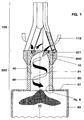
- Fig. 1 shows the overall structure of a burner.
- a swirl generator is 100 effective, the design of which is shown in more detail in the following FIGS. 3-6 and is described.
- This swirl generator 100 is a conical one Formation that is tangential multiple times from a tangentially flowing combustion air flow 115 is applied.
- the current that forms here is based on a transition geometry provided downstream of the swirl generator 100 transitioned seamlessly into a transition piece 200 such that there are none Detachment areas can occur.
- the configuration of this transition geometry is described in more detail in Fig. 6.
- This transition piece 200 is on the outflow side the transition geometry extended by a mixing tube 20, both Parts form the actual mixing section 220.
- the mixing section 220 consist of a single piece, i.e.
- transition piece 200 and the mixing tube 20 into a single continuous structure merge, maintaining the characteristics of each part.
- Transition piece 200 and mixing tube 20 created from two parts so these are connected by a bushing ring 10, the same bushing ring 10 on the head side serves as anchoring surface for the swirl generator 100.
- Such a bushing ring 10 also has the advantage that different mixing tubes are used can.
- the actual combustion chamber is located on the outflow side of the mixing tube 20 30, which is only symbolized here by a flame tube.
- the Mixing section 220 largely fulfills the task that is downstream of the swirl generator 100 a defined route is provided, in which a perfect premix of different types of fuel can be achieved.
- This mixing section so ostensibly the mixing tube 20, furthermore enables lossless flow guidance, so that it is also in operative connection with the transition geometry cannot initially form a backflow zone or backflow bubble, which means that Length of the mixing section 220 influences the quality of the mixture for all types of fuel can be exercised.
- This mixing section 220 has yet another property, which is that the axial velocity profile is in it itself has a pronounced maximum on the axis, so that the Flame from the combustion chamber is not possible. However, it is correct that at in such a configuration, this axial velocity drops towards the wall.
- the mixing tube 20 in Flow and circumferential direction with a number of regular or irregular distributed holes 21 of different cross-sections and directions, through which an amount of air flows into the interior of the mixing tube 20, and along the wall in the sense of a filming an increase in the flow rate induce.
- These holes 21 can also be designed in such a way that the inner wall of the mixing tube 20 at least additionally an effusion cooling established.
- Another possibility is to increase the speed of the mixture To achieve within the mixing tube 20 is that Flow cross-section on the outflow side of the transition channels 201, which already have the called transition geometry form, undergoes a narrowing, whereby the entire speed level within the mixing tube 20 is raised.
- these bores 21 run at an acute angle with respect to the Burner axis 60.
- the outlet corresponds to the transition channels 201 the narrowest flow cross-section of the mixing tube 20.
- the transition channels mentioned 201 accordingly bridge the respective cross-sectional difference, without negatively influencing the flow formed. If the chosen one Precautions when guiding the pipe flow 40 along the mixing pipe 20 causes intolerable pressure loss, this can be remedied, by a diffuser not shown in the figure at the end of this mixing tube is provided.
- a combustion chamber then closes at the end of the mixing tube 20 30 on, with a through a Burner front 70 formed cross-sectional jump is present.
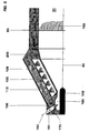
- FIG. 2 shows a schematic view of the burner according to FIG. 1, with particular reference being made to the flushing of a centrally arranged fuel nozzle 103 and to the effect of fuel injectors 170.
- the mode of operation of the remaining main components of the burner, namely swirl generator 100 and transition piece 200, are described in more detail in the following figures.
- the fuel nozzle 103 is encased with a spaced ring 190, in which a number of bores 161 arranged in the circumferential direction are laid, through which a quantity of air 160 flows into an annular chamber 180 and carries out the purging of the fuel lance there.
- These bores 161 are made obliquely forward so that an appropriate axial component is created on the burner axis 60.
- additional fuel injectors 170 are provided, which enter a certain amount, preferably a gaseous fuel, into the respective air amount 160 in such a way that a uniform fuel concentration 150 is established in the mixing tube 20 over the flow cross-section, as shown in FIG Figure symbolizes. It is precisely this uniform fuel concentration 150, in particular the strong concentration on the burner axis 60, that the flame front is stabilized at the outlet of the burner, thus avoiding combustion chamber pulsations.
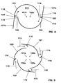
- FIG. 4 is used at the same time as FIG. 3. The following will in the description of Fig. 3 referred to the other figures as needed.
- the first part of the burner according to FIG. 1 forms the swirl generator shown in FIG. 3 100.
- This consists of two hollow conical partial bodies 101, 102 which are nested staggered.
- the number of conical part bodies can of course be greater than two, as shown in Figures 5 and 6; this depends on, as will be explained in more detail below the operating mode of the entire burner. It is with certain operating constellations not excluded, a swirl generator consisting of a single spiral provided.
- the offset of the respective central axis or longitudinal symmetry axes 101b, 102b (see FIG. 4) of the conical partial bodies 101, 102 to one another creates one on each of the neighboring walls in a mirror-image arrangement tangential channel, i.e.
- the conical shape of the partial bodies 101, 102 shown in Flow direction has a certain fixed angle. Of course, ever after operational use, the partial bodies 101, 102 can increase in the direction of flow or have decreasing cone inclination, similar to a trumpet resp. Tulip. The last two forms are not included in the drawing as they are for the expert can be easily understood.
- the two conical partial bodies 101, 102 each have a cylindrical annular starting part 101a. In the area this cylindrical initial part is the fuel nozzle already mentioned in FIG. 2 103 housed, which preferably with a liquid fuel 112 is operated.
- the injection 104 of this fuel 112 coincides with that narrowest cross section of the conical cavity formed by the conical partial bodies 101, 102 114 together.
- the injection capacity and the type of this fuel nozzle 103 depends on the specified parameters of the respective burner.
- the tapered partial bodies 101, 102 furthermore each have a fuel line 108, 109, which are arranged along the tangential air inlet slots 119, 120 and are provided with injection openings 117, through which preferably a gaseous fuel 113 is injected into the combustion air 115 flowing through there is how the arrows 116 symbolize this.
- fuel lines 108, 109 are preferably at the latest at the end of the tangential inflow Entry into the cone cavity 114, arranged to do this for an optimal Obtain air / fuel mixture.
- fuel 112 is normally a liquid Fuel, forming a mixture with another medium, for example with a recirculated flue gas, is easily possible. That fuel 112 is in the cone cavity at a preferably very acute angle 114 injected. A conical fuel spray thus forms from the fuel nozzle 103 105, from the rotating combustion air flowing in tangentially 115 enclosed and dismantled.
- the concentration is then in the axial direction of the injected fuel 112 continuously through the inflowing combustion air 115 degraded to mix in the direction of evaporation.
- the combustion air 115 additionally preheated, or for example with a recycled flue gas or exhaust gas enriched, this supports sustainably the evaporation of the liquid fuel 112 before this mixture into the downstream stage flows, here in the transition piece 200 (see FIGS. 1 and 7).
- the construction of the swirl generator 100 is furthermore excellently suitable, the size of the tangential Air inlet slots 119, 120 to change, so without changing the overall length of the swirl generator 100 covers a relatively large operational bandwidth can be.
- the partial bodies 101, 102 are also in another Plane can be moved relative to one another, which even provides an overlap thereof can be. It is also possible to pass through the partial bodies 101, 102 to interleave a counter-rotating movement in a spiral. Consequently it is possible to change the shape, size and configuration of the tangential air inlet slots 119, 120 to vary as desired, with which the swirl generator 100 is unchanged its overall length can be used universally.
- FIG. 4 shows, among other things, the geometric configuration of optional ones Baffles 121a, 121b. They have a flow initiation function these, according to their length, the respective end of the tapered partial body 101, 102 extend in the direction of flow towards the combustion air 115.
- the channeling of the combustion air 115 into the cone cavity 114 can be done by Open or close the guide plates 121a, 121b by one in the area of the entrance of this channel in the cone cavity 114 pivot point 123 optimized this is particularly necessary if the original gap size of the tangential air inlet slots 119, 120 should be changed dynamically, for example to change the speed of the combustion air 115 to reach.
- these dynamic arrangements can also be static can be provided by using a fixed component as required form the tapered partial body 101, 102.
- FIG. 5 shows, compared to FIG. 4, that the swirl generator 100 now consists of four partial bodies 130, 131, 132, 133 is constructed.
- the associated longitudinal symmetry axes for each sub-body are marked with the letter a.
- this configuration can be said that they are due to the lower twist strength generated with it and in combination with a correspondingly enlarged slot width suitable, the bursting of the vortex flow on the downstream side of the swirl generator To prevent the mixing tube, so that the mixing tube best fulfills its intended role can meet.
- FIG. 6 differs from FIG. 5 in that the partial bodies 140, 141, 142, 143 have a blade profile shape which is used to provide a certain Flow is provided. Otherwise, the mode of operation of the swirl generator is remained the same.
- the admixture of fuel 116 in the combustion air flow 115 happens from the inside of the blade profiles, i.e. the fuel line 108 is now integrated in the individual blades. They are here too Longitudinal axes of symmetry to the individual partial bodies marked with the letter a.
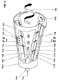
- the transition geometry is corresponding for a swirl generator 100 with four partial bodies 5 or 6, built. Accordingly, the transition geometry points as Natural extension of the upstream part of the four transition channels 201 on, whereby the conical quarter surface of said partial body is extended until it cuts the wall of the mixing tube.
- the same considerations also apply if the swirl generator is based on a principle other than that described under FIG. 3, is constructed.
- the downward surface of the individual Transition channels 201 have a spiral path in the direction of flow Form, which describes a crescent-shaped course, according to the The fact that in the present case the flow cross section of the transition piece 200 flared in the direction of flow.
- the twist angle of the transition channels 201 in the flow direction is selected so that the pipe flow then up to for the cross-sectional jump at the combustion chamber inlet there is still a sufficiently large distance remains to achieve a perfect premix with the injected fuel.
- the measures mentioned above also increase the Axial speed on the mixing tube wall downstream of the swirl generator.
- the transition geometry and the measures in the area of the mixing tube cause one significant increase in the axial speed profile to the center of the mixing tube so that the danger of early ignition is decisively counteracted.
- the flow cross-section of the tube 20 receives a transition radius in this area R, the size of which basically depends on the flow within the Tube 20 depends.
- This radius R is chosen so that the flow adjusts to the Puts on the wall and so the swirl number increases sharply. It can be quantified Define the size of the radius R so that it is> 10% of the inner diameter d of the tube is 20. Compared to a flow without a radius increases now the backflow bladder 50 tremendous.
- This radius R extends to the exit plane of the tube 20, the angle ⁇ between the beginning and end of the curvature ⁇ 90 ° is.
- the tear-off edge A ins runs along one leg of the angle ⁇ Interior of the tube 20 and thus forms a demolition step S compared to the front Point of the tear-off edge A, the depth of which is> 3 mm.
- the angle ⁇ ' the between the tangent of the tear-off edge A and perpendicular to the exit plane of the pipe 20 is the same size as the angle ⁇ .
- the benefits of this training this tear-off edge go from EP-0 780 629 A2 under the chapter "Representation of the invention ".
- Another configuration of the tear-off edge for the same purpose can be achieved with toroid-like notches on the combustion chamber side.
Landscapes
- Engineering & Computer Science (AREA)
- Chemical & Material Sciences (AREA)
- Combustion & Propulsion (AREA)
- Mechanical Engineering (AREA)
- General Engineering & Computer Science (AREA)
- Spray-Type Burners (AREA)
- Pressure-Spray And Ultrasonic-Wave- Spray Burners (AREA)
Description
Die Erfindung betrifft einen Brenner für den Betrieb eines Wärmeerzeugers gemäss Oberbegriff des Anspruchs 1.The invention relates to a burner for the operation of a heat generator according to Preamble of claim 1.
Aus EP-A2-0 780 630 bzw. aus EP-0 780 629 A2 ist ein Brenner bekanntgeworden, der anströmungsseitig aus einem Drallerzeuger besteht, wobei die hierin gebildete Strömung nahtlos in eine Mischstrecke übergeführt wird. Dies geschieht anhand einer am Anfang der Mischstrecke zu diesem Zweck gebildeten Strömungssgeometrie, welche aus Uebergangskanälen besteht, die sektoriell, entsprechend der Zahl der wirkenden Teilkörper des Drallerzeugers, die Stirnfläche der Mischstrecke erfassen und in Strömungsrichtung drallförmig verlaufen. Abströmungsseitig dieser Uebergangskanäle weist die Mischstrecke eine Anzahl Filmlegungsbohrungen auf, welche eine Erhöhung der Strömungsgeschwindigkeit entlang der Rohrwand gewährleisten. Anschliessend folgt eine Brennkammer, wobei der Uebergang zwischen der Mischstrecke und der Brennkammer durch einen Querschnittssprung gebildet wird, in dessen Ebene sich eine Rückströmzone oder Rückströmblase bildet. From EP-A2-0 780 630 and from EP-0 780 629 A2 a burner has become known, which on the inflow side a swirl generator, the flow formed therein seamlessly into one Mixing section is transferred. This is done using one at the beginning of the mixing section flow geometry formed for this purpose, which consists of transition channels exists, which is sectoral, according to the number of acting partial bodies of the swirl generator, capture the end face of the mixing section and in the direction of flow twist. The outflow side of these transition channels has the Mixing section on a number of filming holes, which increase the Ensure flow velocity along the pipe wall. Then follows a combustion chamber, the transition between the mixing section and the Combustion chamber is formed by a cross-sectional jump, in the plane of which forms a backflow zone or backflow bubble.
Die Drallstärke im Drallerzeuger wird denmach so gewählt, dass das Aufplatzen des Wirbels nicht innerhalb der Mischstrecke, sondern weiter stromab erfolgt, wie oben ausgeführt im Bereich des Querschnittssprunges. Die Länge der Mischstrecke ist so dimensioniert, dass eine ausreichende Mischungsgüte für alle Brennstoffarten gewährleistet ist.The swirl strength in the swirl generator is selected so that the bursting of the Vortex not within the mixing section, but further downstream, as above executed in the area of the cross-sectional jump. The length of the mixing section is like this dimensioned to ensure sufficient mix quality for all types of fuel is.
Obschon dieser Brenner gegenüber denjenigen aus dem vorangegangenen Stand der Technik eine signifikante Verbesserung hinsichtlich Stärkung der Flammenstabilität, tieferer Schadstoff-Emissionen, geringerer Pulsationen, vollständigen Ausbrandes, grossen Betriebsbereichs, guter Querzündung zwischen den verschiedenen Brennern, kompakter Bauweise, verbesserter Mischung, etc., gebracht hat, zeigt es sich, dass eine weitere Stärkung der Flammenstabilität sowie eine verbesserte Anpassung der Flamme an die vorgegebene Brennkammergeometrie für einen reibungslosen Betrieb auf höchster Ebene bei der Vormischverbrennung der neueren Generation vonnöten geworden ist, insbesondere wenn es darum geht, die Pulsationen zu eliminieren.Although this burner compared to those from the previous state the technology a significant improvement in terms of strengthening flame stability, lower pollutant emissions, lower pulsations, complete burnout, large operating range, good cross-ignition between the different Burner, compact design, improved mixing, etc., it shows that a further strengthening of flame stability as well as an improved adaptation the flame to the given combustion chamber geometry for a smooth Operation at the highest level in the premix combustion of the newer ones Generation has been needed, especially when it comes to pulsations to eliminate.
Hier will die Erfindung Abhilfe schaffen. Der Erfindung, wie sie in den Ansprüchen gekennzeichnet ist, liegt die Aufgabe zugrunde, bei einem Brenner der eingangs genannten Art Vorkehrungen vorzuschlagen, welche eine Stärkung der Flammenstabilität und eine Anpassung der Flamme an die vorgegebene Brennkammergeometrie bewirken, ohne die übrigen Vorteile dieses Brenners in irgendeiner Weise zu mindern.The invention seeks to remedy this. The invention as set out in the claims is characterized, the task is based on a burner of the type mentioned To propose kind of precautions which strengthen the flame stability and an adaptation of the flame to the given combustion chamber geometry effect without diminishing in any way the other advantages of this burner.
Zu diesem Zweck wird die kopfseitig wirkende und zum Drallerzeuger des Brenners gehörende Brennstoffdüse, welche vorzugsweise auf der Achse des Drallerzeugers bzw. des Brenners angeordnet ist und welche in der Regel mit einem flüssigen Brennstoff gespiesen wird, von einem ringförmigen beabstandeten Mantel umgeben, in welchem in Umfangsrichtung Bohrungen angebracht sind, durch welche eine Luftmenge zur Umspülung der Brennstoffdüse strömt. In Wirkverbindung mit diesen Bohrungen wirken zusätzliche Injektoren, welche vorzugsweise mit einem gasförmigen Brennstoff betrieben werden. Eine geringe Menge Brennstoff wird durch diese Injektoren in die Luftmenge zur Umspülung der Brennstoffdüse eingedüst, dergestalt, dass das für die Stabilität der Flamme wichtige Zentrum der Brennerströmung stets im richtigen Mass versorgt wird. Damit wird erreicht, dass sich eine gleichmässige Brennstoffkonzentration über den Strömungsquerschnitt des Brenners einstellt, welche zu einer Unterdrückung von Brennkammerschwingungen führen. Diese gleichmässige Brennstoffkonzentration über den Strömungsquerschnitt macht sich insbesondere auf der Brennerachse bemerkbar, wo erfahrungsgemäss wegen ungleichmässiger Brennstoffanreicherung die Schwingungen in der Flammenfront entstehen, welche zu Pulsationen führen. Darüber hinaus wird mit der Unterdrückung der Brennkammerschwingungen der Betriebsbereich des Brenners wesentlich erweitert, da keine Instabilität der Flamme mehr zu befürchten ist, welche zu eine Verschlechterung der Löschgrenze führt.For this purpose, the one acting on the head and the swirl generator of the burner belonging fuel nozzle, which is preferably on the axis of the swirl generator or the burner and which is usually with a liquid Fuel is fed, surrounded by an annular spaced jacket, in which holes are made in the circumferential direction, through which a Air volume flows around the fuel nozzle. In active connection with these Holes act additional injectors, which are preferably with a gaseous Fuel operated. A small amount of fuel is generated by this Injectors injected into the air volume for flushing around the fuel nozzle, in such a way that the center of the burner flow, which is important for the stability of the flame, always is supplied to the right extent. This ensures that there is a uniform Fuel concentration over the flow cross section of the burner, which lead to suppression of combustion chamber vibrations. This even Fuel concentration across the flow cross-section is particularly important noticeable on the burner axis, where experience has shown it to be uneven Fuel enrichment the vibrations in the flame front arise which lead to pulsations. In addition, with the suppression of Combustion chamber vibrations significantly expand the operating range of the burner, since there is no longer any fear of instability of the flame, which leads to deterioration the deletion limit.
Ein weiterer Vorteil der Erfindung ist darin zu sehen, dass die Spülluft durch die genannten Oeffnungen im Bereich der Brennstoffdüse eine Benetzung der Innenwand des kegelförmigen Drallerzeugers durch den eingedüsten flüssigen Brennstoff verhindert.Another advantage of the invention is the fact that the purge air through the above Openings in the area of the fuel nozzle wetting the inner wall of the conical swirl generator prevented by the injected liquid fuel.
Vorteilhafte und zweckmässige Weiterbildungen der erfindungsgemässen Aufgabenlösung sind in den weiteren Ansprüchen gekennzeichnet.Advantageous and expedient developments of the task solution according to the invention are characterized in the further claims.
Im folgenden werden anhand der Zeichnungen Ausführungsbeispiele der Erfindung näher erläutert. Alle für das unmittelbare Verständnis der Erfindung unwesentlichen Merkmale sind fortgelassen worden. Gleiche Elemente sind in den verschiedenen Figuren mit den gleichen Bezugszeichen versehen. Die Strömungsrichtung der Medien ist mit Pfeilen angegeben.Exemplary embodiments of the invention are described below with reference to the drawings explained in more detail. All of which are insignificant for the immediate understanding of the invention Features have been left out. The same elements are in the different Figures with the same reference numerals. The flow direction of the media is indicated with arrows.
Es zeigt:
- Fig. 1
- einen als Vormischbrenner ausgelegten Brenner mit einer Mischstrecke stromab eines Drallerzeugers,
- Fig. 2
- eine schematische darstellung des Brenners gemäss Fig. 1 mit Disposition der zusätzlichen Brennstoff-Injektoren,
- Fig. 3
- einen aus mehreren Schalen bestehenden Drallerzeuger in perspektivischer Darstellung, entsprechend aufgeschnitten,
- Fig. 4
- einen Querschnitt durch einen zweischaligen Drallerzeuger,
- Fig. 5
- einen Querschnitt durch einen vierschaligen Drallerzeuger,
- Fig. 6
- eine Ansicht durch einen Drallerzeuger, dessen Schalen schaufelförmig profiliert sind,
- Fig. 7
- eine Ausgestaltung der Uebergangsgeometrie zwischen Drallerzeuger und Mischstrecke und
- Fig. 8
- eine Abrisskante zur räumlichen Stabilisierung der Rückströmzone.
- Fig. 1
- a burner designed as a premix burner with a mixing section downstream of a swirl generator,
- Fig. 2
- 2 shows a schematic representation of the burner according to FIG. 1 with disposition of the additional fuel injectors,
- Fig. 3
- a swirl generator consisting of several shells in a perspective view, cut open accordingly,
- Fig. 4
- a cross section through a double-shell swirl generator,
- Fig. 5
- a cross section through a four-shell swirl generator,
- Fig. 6
- 2 shows a view through a swirl generator, the shells of which are profiled in a shovel shape,
- Fig. 7
- an embodiment of the transition geometry between swirl generator and mixing section and
- Fig. 8
- a tear-off edge for spatial stabilization of the backflow zone.
Fig. 1 zeigt den Gesamtaufbau eines Brenners. Anfänglich ist ein Drallerzeuger 100
wirksam, dessen Ausgestaltung in den nachfolgenden Fig. 3-6 noch näher gezeigt
und beschrieben wird. Es handelt sich bei diesem Drallerzeuger 100 um ein kegelförmiges
Gebilde, das tangential mehrfach von einem tangential einströmenden Verbrennungsluftstromes
115 beaufschlagt wird. Die sich hierein bildende Strömung
wird anhand einer stromab des Drallerzeugers 100 vorgesehenen Uebergangsgeometrie
nahtlos in ein Uebergangsstück 200 übergeleitet, dergestalt, dass dort keine
Ablösungsgebiete auftreten können. Die Konfiguration dieser Uebergangsgeometrie
wird unter Fig. 6 näher beschrieben. Dieses Uebergangsstück 200 ist abströmungsseitig
der Uebergangsgeometrie durch ein Mischrohr 20 verlängert, wobei beide
Teile die eigentliche Mischstrecke 220 bilden. Selbstverständlich kann die Mischstrecke
220 aus einem einzigen Stück bestehen, d.h. dann, dass das Uebergangsstück
200 und das Mischrohr 20 zu einem einzigen zusammenhängenden Gebilde
verschmelzen, wobei die Charakteristiken eines jeden Teils erhalten bleiben. Werden
Uebergangsstück 200 und Mischrohr 20 aus zwei Teilen erstellt, so sind diese
durch einen Buchsenring 10 verbunden, wobei der gleiche Buchsenring 10 kopfseitig
als Verankerungsfläche für den Drallerzeuger 100 dient. Ein solcher Buchsenring 10
hat darüber hinaus den Vorteil, dass verschiedene Mischrohre eingesetzt werden
können. Abströmungsseitig des Mischrohres 20 befindet sich die eigentliche Brennkammer
30, welche hier lediglich durch ein Flammrohr versinnbildlicht ist. Die
Mischstrecke 220 erfüllt weitgehend die Aufgabe, dass stromab des Drallerzeugers
100 eine definierte Strecke bereitgestellt wird, in welcher eine perfekte Vormischung
von Brennstoffen verschiedener Art erzielt werden kann. Diese Mischstrecke, also
vordergründig das Mischrohr 20, ermöglicht des weiteren eine verlustfreie Strömungsführung,
so dass sich auch in Wirkverbindung mit der Uebergangsgeometrie
zunächst keine Rückströmzone oder Rückströmblase bilden kann, womit über die
Länge der Mischstrecke 220 auf die Mischungsgüte für alle Brennstoffarten Einfluss
ausgeübt werden kann. Diese Mischstrecke 220 hat aber noch eine andere Eigenschaft,
welche darin besteht, dass in ihr selbst das Axialgeschwindigkeits-Profil ein
ausgeprägtes Maximum auf der Achse besitzt, so dass eine Rückzündung der
Flamme aus der Brennkammer nicht möglich ist. Allerdings ist es richtig, dass bei
einer solchen Konfiguration diese Axialgeschwindigkeit zur Wand hin abfällt. Um
Rückzündung auch in diesem Bereich zu unterbinden, wird das Mischrohr 20 in
Strömungs- und Umfangsrichtung mit einer Anzahl regelmässig oder unregelmässig
verteilter Bohrungen 21 verschiedenster Querschnitte und Richtungen versehen,
durch welche eine Luftmenge in das Innere des Mischrohres 20 strömt, und entlang
der Wand im Sinne einer Filmlegung eine Erhöhung der Durchfluss-Geschwindigkeit
induzieren. Diese Bohrungen 21 können auch so ausgelegt werden, dass sich an
der Innenwand des Mischrohres 20 mindestens zusätzlich noch eine Effusionskühlung
einstellt. Eine andere Möglichkeit eine Erhöhung der Geschwindigkeit des Gemisches
innerhalb des Mischrohres 20 zu erzielen, besteht darin, dass dessen
Durchflussquerschnitt abströmungsseitig der Uebergangskanäle 201, welche die bereits
genannten Uebergangsgeometrie bilden, eine Verengung erfährt, wodurch das
gesamte Geschwindigkeitsniveau innerhalb des Mischrohres 20 angehoben wird. In
der Figur verlaufen diese Bohrungen 21 unter einem spitzen Winkel gegenüber der
Brennerachse 60. Des weiteren entspricht der Auslauf der Uebergangskanäle 201
dem engsten Durchflussquerschnitt des Mischrohres 20. Die genannten Uebergangskanäle
201 überbrücken demnach den jeweiligen Querschnittsunterschied,
ohne dabei die gebildete Strömung negativ zu beeinflussen. Wenn die gewählte
Vorkehrung bei der Führung der Rohrströmung 40 entlang des Mischrohres 20 einen
nicht tolerierbaren Druckverlust auslöst, so kann hiergegen Abhilfe geschaffen werden,
indem am Ende dieses Mischrohres ein in der Figur nicht gezeigter Diffusor
vorgesehen wird. Am Ende des Mischrohres 20 schliesst sich sodann eine Brennkammer
30 an, wobei zwischen den beiden Durchflussquerschnitten ein durch eine
Brennerfront 70 gebildeter Querschnittssprung vorhanden ist. Erst hier bildet sich eine
zentrale Flammenfront mit einer Rückströmzone 50, welche gegenüber der
Flammenfront die Eigenschaften eines körperlosen Flammenhalters aufweist. Bildet
sich innerhalb dieses Querschnittssprunges während des Betriebes eine strömungsmässige
Randzone, in welcher durch den dort vorherrschenden Unterdruck
Wirbelablösungen entstehen, so führt dies zu einer verstärkten Ringstabilisation der
Rückströmzone 50. Stirnseitig weist die Brennkammer 30 eine Anzahl Oeffnungen
31 auf, durch welche eine Luftmenge direkt in den Querschnittssprung strömt, und
dort unteren anderen dazu beiträgt, dass die Ringstabilisation der Rückströmzone 50
gestärkt wird. Danebst darf nicht unerwähnt bleiben, dass die Erzeugung einer stabilen
Rückströmzone 50 auch eine ausreichend hohe Drallzahl in einem Rohr erfordert.
Ist eine solche zunächst unerwünscht, so können stabile Rückströmzonen
durch die Zufuhr kleiner stark verdrallter Luftströmungen am Rohrende, beispielsweise
durch tangentiale Oeffnungen, erzeugt werden. Dabei geht man hier davon aus,
dass die hierzu benötigte Luftmenge in etwa 5-20% der Gesamtluftmenge beträgt.
Was die Ausgestaltung der Brennerfront 70 am Ende des Mischrohres 20 zur Stabilisierung
der Rückströmzone oder Rückströmblase 50 betrifft, wird auf die Beschreibung
unter Fig. 8 verwiesen.Fig. 1 shows the overall structure of a burner. Initially, a swirl generator is 100
effective, the design of which is shown in more detail in the following FIGS. 3-6
and is described. This
Fig. 2 zeigt eine schematische Ansicht des Brenners gemäss Fig. 1, wobei hier insbesondere
auf die Umspülung einer zentral angeordneten Brennstoffdüse 103 und
auf die Wirkung von Brennstoff-Injektoren 170 hingewiesen wird. Die Wirkungsweise
der restlichen Hauptbestandteile des Brenners, nämlich Drallerzeuger 100 und Uebergangsstück
200 werden unter den nachfolgenden Figuren näher beschrieben.
Die Brennstoffdüse 103 wird mit einem beabstandeten Ring 190 ummantelt, in welchem
eine Anzahl in Umfangsrichtung disponierter Bohrungen 161 gelegt sind, durch
welche eine Luftmenge 160 in eine ringförmige Kammer 180 strömt und dort die
Umspülung der Brennstofflanze vornimmt. Diese Bohrungen 161 sind schräg nach
vorne angelegt, dergestalt, dass eine angemessene axiale Komponente auf der
Brennerachse 60 entsteht. In Wirkverbindung mit diesen Bohrungen 161 sind zusätzliche
Brennstoff-Injektoren 170 vorgesehen, welche eine bestimmte Menge vorzugsweise
eines gasförmigen Brennstoffes in die jeweilige Luftmenge 160 eingeben,
dergestalt, dass sich im Mischrohr 20 eine gleichmässige Brennstoffkonzentration
150 über den Strömungsquerschnitt einstellt, wie die Darstellung in der Figur versinnbildlichen
will. Genau diese gleichmässige Brennstoffkonzentration 150, insbesondere
die starke Konzentration auf der Brennerachse 60 sorgt dafür, dass sich eine
Stabilisierung der Flammenfront am Ausgangs des Brenners einstellt, womit aufkommende
Brennkammerpulsationen vermieden werden.FIG. 2 shows a schematic view of the burner according to FIG. 1, with particular reference being made to the flushing of a centrally arranged
The
Um den Aufbau des Drallerzeugers 100 besser zu verstehen, ist es von Vorteil,
wenn gleichzeitig zu Fig. 3 mindestens Fig. 4 herangezogen wird. Im folgenden wird
bei der Beschreibung von Fig. 3 nach Bedarf auf die übrigen Figuren hingewiesen.In order to better understand the structure of the
Der erste Teil des Brenners nach Fig. 1 bildet den nach Fig. 3 gezeigten Drallerzeuger
100. Dieser besteht aus zwei hohlen kegelförmigen Teilkörpem 101, 102, die
versetzt zueinander ineinandergeschachtelt sind. Die Anzahl der kegelförmigen Teilkörper
kann selbstverständlich grösser als zwei sein, wie die Figuren 5 und 6 zeigen;
dies hängt jeweils, wie weiter unten noch näher zur Erläuterung kommen wird, von
der Betriebsart des ganzen Brenners ab. Es ist bei bestimmten Betriebskonstellationen
nicht ausgeschlossen, einen aus einer einzigen Spirale bestehenden Drallerzeuger
vorzusehen. Die Versetzung der jeweiligen Mittelachse oder Längssymmetrieachsen
101b, 102b (Vgl. Fig. 4) der kegeligen Teilkörper 101, 102 zueinander
schafft bei der benachbarten Wandung, in spiegelbildlicher Anordnung, jeweils einen
tangentialen Kanal, d.h. einen Lufteintrittsschlitz 119, 120 (Vgl. Fig. 4), durch welche
die Verbrennungsluft 115 in Innenraum des Drallerzeugers 100, d.h. in den Kegelhohlraum
114 desselben strömt. Die Kegelform der gezeigten Teilkörper 101, 102 in
Strömungsrichtung weist einen bestimmten festen Winkel auf. Selbstverständlich, je
nach Betriebseinsatz, können die Teilkörper 101, 102 in Strömungsrichtung eine zunehmende
oder abnehmende Kegelneigung aufweisen, ähnlich einer Trompete resp.
Tulpe. Die beiden letztgenannten Formen sind zeichnerisch nicht erfasst, da sie für
den Fachmann ohne weiteres nachempfindbar sind. Die beiden kegeligen Teilkörper
101, 102 weisen je einen zylindrischen ringförmigen Anfangsteil 101a auf. Im Bereich
dieses zylindrischen Anfangsteils ist die bereits unter Fig. 2 erwähnte Brennstoffdüse
103 untergebracht, welche vorzugsweise mit einem flüssigen Brennstoff
112 betrieben wird. Die Eindüsung 104 dieses Brennstoffes 112 fällt in etwa mit dem
engsten Querschnitt des durch die kegeligen Teilkörper 101, 102 gebildeten Kegelhohlraumes
114 zusammen. Die Eindüsungskapazität und die Art dieser Brennstoffdüse
103 richtet sich nach den vorgegebenen Parametern des jeweiligen Brenners.
Die kegeligen Teilkörper 101, 102 weisen des weiteren je eine Brennstoffleitung 108,
109 auf, welche entlang der tangentialen Lufteintrittsschlitze 119, 120 angeordnet
und mit Eindüsungsöffnungen 117 versehen sind, durch welche vorzugsweise ein
gasförmiger Brennstoff 113 in die dort durchströmende Verbrennungsluft 115 eingedüst
wird, wie dies die Pfeile 116 versinnbildlichen wollen. Diese Brennstoffleitungen
108, 109 sind vorzugsweise spätestens am Ende der tangentialen Einströmung, vor
Eintritt in den Kegelhohlraum 114, angeordnet, dies um eine optimale
Luft/Brennstoff-Mischung zu erhalten. Bei dem durch die Brennstoffdüse 103 herangeführten
Brennstoff 112 handelt es sich, wie erwähnt, im Normalfall um einen flüssigen
Brennstoff, wobei eine Gemischbildung mit einem anderen Medium, beispielsweise
mit einem rückgeführten Rauchgas, ohne weiteres möglich ist. Dieser Brennstoff
112 wird unter einem vorzugsweise sehr spitzen Winkel in den Kegelhohlraum
114 eingedüst. Aus der Brennstoffdüse 103 bildet sich sonach ein kegeliges Brennstoffspray
105, das von der tangential einströmenden rotierenden Verbrennungsluft
115 umschlossen und abgebaut wird. In axialer Richtung wird sodann die Konzentration
des eingedüsten Brennstoffes 112 fortlaufend durch die einströmenden Verbrennungsluft
115 zu einer Vermischung Richtung Verdampfung abgebaut. Wird ein
gasförmiger Brennstoff 113 über die Oeffnungsdüsen 117 eingebracht, geschieht die
Bildung des Brennstoff/Luft-Gemisches direkt am Ende der Lufteintrittsschlitze 119,
120. Ist die Verbrennungsluft 115 zusätzlich vorgeheizt, oder beispielsweise mit einem
rückgeführten Rauchgas oder Abgas angereichert, so unterstützt dies nachhaltig
die Verdampfung des flüssigen Brennstoffes 112, bevor dieses Gemisch in die
nachgeschaltete Stufe strömt, hier in das Uebergangsstück 200 (Vgl. Fig. 1 und 7).
Die gleichen Ueberlegungen gelten auch, wenn über die Leitungen 108, 109 flüssige
Brennstoffe zugeführt werden sollten. Bei der Gestaltung der kegeligen Teilkörper
101, 102 hinsichtlich des Kegelwinkels und der Breite der tangentialen Lufteintrittsschlitze
119, 120 sind an sich enge Grenzen einzuhalten, damit sich das gewünschte
Strömungsfeld der Verbrennungsluft 115 am Ausgang des Drallerzeugers 100 einstellen
kann. Allgemein ist zu sagen, dass eine Verkleinerung der tangentialen
Lufteintrittsschlitze 119, 120 die schnellere Bildung einer Rückströmzone bereits im
Bereich des Drallerzeugers begünstigt. Die Axialgeschwindigkeit innerhalb des Drallerzeugers
100 lässt sich durch eine entsprechende unter Fig. 2 (Pos. 160) näher
beschriebene Zuführung einer Luftmenge erhöhen bzw. stabilisieren. Eine entsprechende
Drallerzeugung in Wirkverbindung mit dem nachgeschalteten Uebergangsstück
200 (Vgl. Fig. 1 und 7) verhindert die Bildung von Strömungsablösungen innerhalb
des dem Drallerzeuger 100 nachgeschalteten Mischrohr. Die Konstruktion
des Drallerzeugers 100 eignet sich des weiteren vorzüglich, die Grösse der tangentialen
Lufteintrittsschlitze 119, 120 zu verändern, womit ohne Veränderung der Baulänge
des Drallerzeugers 100 eine relativ grosse betriebliche Bandbreite erfasst
werden kann. Selbstverständlich sind die Teilkörper 101, 102 auch in einer anderen
Ebene zueinander verschiebbar, wodurch sogar eine Ueberlappung derselben vorgesehen
werden kann. Es ist des weiteren möglich, die Teilkörper 101, 102 durch
eine gegenläufig drehende Bewegung spiralartig ineinander zu verschachteln. Somit
ist es möglich, die Form, die Grösse und die Konfiguration der tangentialen Lufteintrittsschlitze
119, 120 beliebig zu variieren, womit der Drallerzeuger 100 ohne Veränderung
seiner Baulänge universell einsetzbar ist.The first part of the burner according to FIG. 1 forms the swirl generator shown in FIG. 3
100. This consists of two hollow conical
Aus Fig. 4 geht unter anderen die geometrische Konfiguration von wahlweise vorzusehenden
Leitbleche 121a, 121b hervor. Sie haben Strömungseinleitungsfunktion,
wobei diese, entsprechend ihrer Länge, das jeweilige Ende der kegeligen Teilkörper
101, 102 in Anströmungsrichtung gegenüber der Verbrennungsluft 115 verlängern.
Die Kanalisierung der Verbrennungsluft 115 in den Kegelhohlraum 114 kann durch
Oeffnen bzw. Schliessen der Leitbleche 121 a, 121b um einen im Bereich des Eintritts
dieses Kanals in den Kegelhohlraum 114 plazierten Drehpunkt 123 optimiert
werden, insbesondere ist dies vonnöten, wenn die ursprüngliche Spaltgrösse der
tangentialen Lufteintrittsschlitze 119, 120 dynamisch verändert werden soll, beispielsweise
um eine Aenderung der geschwindigkeit der Verbrennungsluft 115 zu
erreichen. Selbstverständlich können diese dynamische Vorkehrungen auch statisch
vorgesehen werden, indem bedarfsmässige Leitbleche einen festen Bestandteil mit
den kegeligen Teilkörpem 101, 102 bilden.4 shows, among other things, the geometric configuration of optional ones
Baffles 121a, 121b. They have a flow initiation function
these, according to their length, the respective end of the tapered
Fig. 5 zeigt gegenüber Fig. 4, dass der Drallerzeuger 100 nunmehr aus vier Teilkörpem
130, 131, 132, 133 aufgebaut ist. Die dazugehörigen Längssymmetrieachsen
zu jedem Teilkörper sind mit der Buchstabe a gekennzeichnet. Zu dieser Konfiguration
ist zu sagen, dass sie sich aufgrund der damit erzeugten, geringeren Drallstärke
und im Zusammenwirken mit einer entsprechend vergrösserten Schlitzbreite bestens
eignet, das Aufplatzen der Wirbelströmung abströmungsseitig des Drallerzeugers im
Mischrohr zu verhindern, womit das Mischrohr die ihm zugedachte Rolle bestens
erfüllen kann.5 shows, compared to FIG. 4, that the
Fig. 6 unterscheidet sich gegenüber Fig. 5 insoweit, als hier die Teilkörper 140, 141,
142, 143 eine Schaufelprofilform haben, welche zur Bereitstellung einer gewissen
Strömung vorgesehen wird. Ansonsten ist die Betreibungsart des Drallerzeugers die
gleiche geblieben. Die Zumischung des Brennstoffes 116 in den Verbrennungsluftstromes
115 geschieht aus dem Innern der Schaufelprofile heraus, d.h. die Brennstoffleitung
108 ist nunmehr in die einzelnen Schaufeln integriert. Auch hier sind die
Längssymmetrieachsen zu den einzelnen Teilkörpern mit der Buchstabe a gekennzeichnet.FIG. 6 differs from FIG. 5 in that the
Fig. 7 zeigt das Uebergangsstück 200 in dreidimensionaler Ansicht. Die Uebergangsgeometrie
ist für einen Drallerzeuger 100 mit vier Teilkörpern, entsprechend
der Fig. 5 oder 6, aufgebaut. Dementsprechend weist die Uebergangsgeometrie als
natürliche Verlängerung der stromauf wirkenden Teilkörper vier Uebergangskanäle
201 auf, wodurch die Kegelviertelfläche der genannten Teilkörper verlängert wird, bis
sie die Wand des Mischrohres schneidet. Die gleichen Ueberlegungen gelten auch,
wenn der Drallerzeuger aus einem anderen Prinzip, als den unter Fig. 3 beschriebenen,
aufgebaut ist. Die nach unten in Strömungsrichtung verlaufende Fläche der einzelnen
Uebergangskanäle 201 weist eine in Strömungsrichtung spiralförmig verlaufende
Form auf, welche einen sichelförmigen Verlauf beschreibt, entsprechend der
Tatsache, dass sich vorliegend der Durchflussquerschnitt des Uebergangsstückes
200 in Strömungsrichtung konisch erweitert. Der Drallwinkel der Uebergangskanäle
201 in Strömungsrichtung ist so gewählt, dass der Rohrströmung anschliessend bis
zum Querschnittssprung am Brennkammereintritt noch eine genügend grosse Strekke
verbleibt, um eine perfekte Vormischung mit dem eingedüsten Brennstoff zu bewerkstelligen.
Femer erhöht sich durch die oben genannten Massnahmen auch die
Axialgeschwindigkeit an der Mischrohrwand stromab des Drallerzeugers. Die Uebergangsgeometrie
und die Massnahmen im Bereich des Mischrohres bewirken eine
deutliche Steigerung des Axialgeschwindigkeitsprofils zum Mittelpunkt des Mischrohres
hin, so dass der Gefahr einer Frühzündung entscheidend entgegengewirkt wird.7 shows the
Fig. 8 zeigt die bereits angesprochene Abrisskante, welche am Brenneraustritt gebildet
ist. Der Durchflussquerschnitt des Rohres 20 erhält in diesem Bereich einen Uebergangsradius
R, dessen Grösse grundsätzlich von der Strömung innerhalb des
Rohres 20 abhängt. Dieser Radius R wird so gewählt, dass sich die Strömung an die
Wand anlegt und so die Drallzahl stark ansteigen lässt. Quantitativ lässt sich die
Grösse des Radius R so definieren, dass dieser > 10% des Innendurchmessers d
des Rohres 20 beträgt. Gegenüber einer Strömung ohne Radius vergrössert sich
nun die Rückströmblase 50 gewaltig. Dieser Radius R verläuft bis zur Austrittsebene
des Rohres 20, wobei der Winkei β zwischen Anfang und Ende der Krümmung < 90°
beträgt. Entlang des einen Schenkels des Winkels β verläuft die Abrisskante A ins
Innere des Rohres 20 und bildet somit eine Abrissstufe S gegenüber dem vorderen
Punkt der Abrisskante A, deren Tiefe > 3 mm beträgt. Selbstverständlich kann die
hier parall zur Austrittsebene des Rohres 20 verlaufende Kante anhand eines gekrümmten
Verlaufs wieder auf Stufe Austrittsebene gebracht werden. Der Winkel β',
der sich zwischen Tangente der Abrisskante A und Senkrechte zur Austrittsebene
des Rohres 20 ausbreitet, ist gleich gross wie Winkel β. Die Vorteile dieser Ausbildung
dieser Abrisskante gehen aus EP-0 780 629 A2 unter Dem Kapitel "Darstellung
der Erfindung" hervor.Eine weitere Ausgestaltung der Abrisskante zum selben Zweck
lässt sich mit brennkammerseitigen torusähnlichen Einkerbungen erreichen.8 shows the tear-off edge already mentioned, which is formed at the burner outlet
is. The flow cross-section of the
- 1010
- BuchenringBuchenring
- 2020
-
Mischrohr, Teil der Mischstrecke 220Mixing tube, part of the
mixing section 220 - 2121
- Bohrungen, OeffnungenHoles, openings
- 3030
- Brennkammercombustion chamber
- 3131
- OeffnungenOpenings
- 4040
- Strömung, Rohrströmung im Mischrohr, HauptströmungFlow, pipe flow in the mixing pipe, main flow
- 5050
- Rückströmzone, RückströmblaseBackflow zone, backflow bubble
- 6060
- BrennerachseBrenner
- 100100
- Drallerzeugerswirl generator
- 101, 102101, 102
- Kegelförmige TeilkörperPartial conical body
- 101a101
- Ringförmiger AnfangsteilAnnular initial part
- 101b, 102b101b, 102b
- LängssymmetrieachsenLongitudinal axes of symmetry
- 103103
- Brennstoffdüsefuel nozzle
- 104104
- Brennstoffeindüsungfuel injection
- 105105
- Brennstoffspray (Brennstoffeindüsungsprofil)Fuel spray (fuel injection profile)
- 108, 109108, 109
- Brennstoffleitungenfuel lines
- 112112
- Flüssiger BrennstoffLiquid fuel
- 113113
- Gasförmiger BrennstoffGaseous fuel
- 114114
- Kegelhohlraumconical cavity
- 115115
- Verbrennungsluft (Verbrennungsluftstrom)Combustion air (combustion air flow)
- 116116
-
Brennstoff Eindüsung aus den Leitungen 108, 109Fuel injection from
lines - 117117
- Brennstoffdüsenfuel nozzles
- 119, 120119, 120
- Tangentiale Lufteintrittsschlitze Tangential air inlet slots
- 121a, 121b121a, 121b
- Leitblechebaffles
- 123123
- Drehpunkt der LeitblechePivot point of the guide plates
- 130, 131, 132, 133130, 131, 132, 133
- Teilkörperpartial body
- 131a, 131a, 132a, 133a131a, 131a, 132a, 133a
- LängssymmetrieachsenLongitudinal axes of symmetry
- 140, 141, 142, 143140, 141, 142, 143
- Schaufelprofilförmige TeilkörperVane-shaped partial body
- 140a, 141a, 142a, 143a140a, 141a, 142a, 143a
- LängssymmetrieachsenLongitudinal axes of symmetry
- 150150
- Brennstoffkonzentrationfuel concentration
- 160160
- Luftmenge, MischluftAir volume, mixed air
- 161161
- Bohrungen, OeffnungenHoles, openings
- 170170
- Brennstoff-InjektorenFuel injectors
- 180180
- Ringförmige LuftkammerAnnular air chamber
- 190190
- Ringring
- 200200
-
Uebergangsstück, Teil der Mischstrecke 220Transition piece, part of the
mixing section 220 - 201201
- UebergangskanäleTransition passages
- 220220
- Mischstreckemixing section
Claims (15)
- Burner for operating a heat generator, the burner essentially comprising a swirl generator (100) for a combustion-air flow and means for injecting (103, 117) at least one fuel (112, 113) into the combustion-air flow (115), the means for injecting (103, 117) at least one fuel (112, 113) comprising at least one central fuel nozzle (103), arranged on the head side of the swirl generator (100), a mixing section (220) being arranged downstream of the swirl generator (100) and having, inside a first portion of the section in the direction of flow, a number of transition passages (201) for passing a flow formed in the swirl generator (100) into a mixing tube arranged downstream of these transition passages (201) and merging into a burner front, the swirl generator (100) having a ring (190) arranged around the central fuel nozzle (103), on the head side of the swirl generator (100), and the ring (190) having a number of bores (161) arranged in the circumferential direction,
characterized in that
fuel injectors (170) are arranged within the bores (161) of the ring (190), by means of which a fuel can be injected into an air quantity (160) flowing through the bores (161). - Burner according to Claim 1, characterized in that the bores (161) are directed so as to slant forwards.
- Burner according to Claim 1, characterized in that the fuel nozzle (103) is surrounded by an annular air chamber (180).
- Burner according to Claim 1, characterized in that the burner front of the mixing tube (20) to the downstream combustion chamber (30) is formed with a breakaway edge (A).
- Burner according to Claim 1, characterized in that the number of transition passages (201) in the mixing section (220) corresponds to the number of partial flows formed by the swirl generator (100).
- Burner according to Claim 1, characterized in that the mixing tube (20) arranged downstream of the transition passages (201) is provided with openings (21) in the direction of flow and in the peripheral direction for injecting an air flow into the interior of the mixing tube (20).
- Burner according to Claim 6, characterized in that the openings (21) run at an acute angle relative to the burner axis (60) of the mixing tube (20).
- Burner according to Claim 1, characterized in that the cross section of flow of the mixing tube (20) downstream of the transition passages (201) is less than, equal to or greater than the cross section of the flow (40) formed in the swirl generator (100, 100a).
- Burner according to Claim 1, characterized in that a combustion chamber (30) is arranged downstream of the mixing section (220), in that there is a jump in cross section between the mixing section (220) and the combustion chamber (30), which jump in cross section induces the initial cross section of flow of the combustion chamber (30), and in that a backflow zone (50) can take effect in the region of this jump in cross section.
- Burner according to Claim 1, characterized in that there is a diffuser and/or a venturi section upstream of the burner front (70).
- Burner according to Claim 1, characterized in that the swirl generator (100) consists of at least two hollow, conical sectional bodies (101, 102; 130, 131, 132, 133; 140, 141, 142, 143) which are nested one inside the other in the direction of flow, in that the respective longitudinal symmetry axes (101b, 102b; 130a, 131a, 132a, 133a; 140a, 141a, 142a, 143a) of these sectional bodies run mutually offset in such a way that the adjacent walls of the sectional bodies form ducts (119, 120), tangential in their longitudinal extent, for a combustion-air flow (115), and in that at least one fuel nozzle (103) can take effect in the interior space (114) formed by the sectional bodies.
- Burner according to Claim 11, characterized in that further fuel nozzles (117) are arranged in the region of the tangential ducts (119, 120) in their longitudinal extent.
- Burner according to Claim 11, characterized in that the sectional bodies (140, 141, 142, 143) have a blade-shaped profile in cross section.
- Burner according to Claim 11, characterized in that the sectional bodies have a fixed cone angle, increasing conicity, or decreasing conicity in the direction of flow.
- Burner according to Claim 11, characterized in that the sectional bodies are nested spirally one inside the other.
Priority Applications (5)
| Application Number | Priority Date | Filing Date | Title |
|---|---|---|---|
| DE59709791T DE59709791D1 (en) | 1997-09-19 | 1997-09-19 | Burner for operating a heat generator |
| EP97810687A EP0903540B1 (en) | 1997-09-19 | 1997-09-19 | Burner for operating a heat generator |
| US09/153,269 US5944511A (en) | 1997-09-19 | 1998-09-14 | Burner for operating a heat generator |
| CNB981192939A CN1143077C (en) | 1997-09-19 | 1998-09-18 | Burners for operating heat generators |
| JP26681698A JP4155635B2 (en) | 1997-09-19 | 1998-09-21 | Burner for operating the heat generator |
Applications Claiming Priority (1)
| Application Number | Priority Date | Filing Date | Title |
|---|---|---|---|
| EP97810687A EP0903540B1 (en) | 1997-09-19 | 1997-09-19 | Burner for operating a heat generator |
Publications (2)
| Publication Number | Publication Date |
|---|---|
| EP0903540A1 EP0903540A1 (en) | 1999-03-24 |
| EP0903540B1 true EP0903540B1 (en) | 2003-04-09 |
Family
ID=8230395
Family Applications (1)
| Application Number | Title | Priority Date | Filing Date |
|---|---|---|---|
| EP97810687A Expired - Lifetime EP0903540B1 (en) | 1997-09-19 | 1997-09-19 | Burner for operating a heat generator |
Country Status (5)
| Country | Link |
|---|---|
| US (1) | US5944511A (en) |
| EP (1) | EP0903540B1 (en) |
| JP (1) | JP4155635B2 (en) |
| CN (1) | CN1143077C (en) |
| DE (1) | DE59709791D1 (en) |
Families Citing this family (11)
| Publication number | Priority date | Publication date | Assignee | Title |
|---|---|---|---|---|
| EP0918191B1 (en) * | 1997-11-21 | 2003-07-02 | Alstom | Burner for the operation of a heat generator |
| DE59807856D1 (en) * | 1998-01-23 | 2003-05-15 | Alstom Switzerland Ltd | Burner for operating a heat generator |
| DE19914666B4 (en) * | 1999-03-31 | 2009-08-20 | Alstom | Burner for a heat generator |
| WO2001077182A1 (en) * | 2000-04-07 | 2001-10-18 | Matsushita Electric Industrial Co., Ltd. | Antibody/carrier complex, process for producing the same, method of controlling antigen-antibody reaction by using the same and immunoassay method |
| WO2001096785A1 (en) * | 2000-06-15 | 2001-12-20 | Alstom (Switzerland) Ltd | Method for operating a burner and burner with stepped premix gas injection |
| DE10051221A1 (en) * | 2000-10-16 | 2002-07-11 | Alstom Switzerland Ltd | Burner with staged fuel injection |
| US20050065136A1 (en) * | 2003-08-13 | 2005-03-24 | Roby Russell R. | Methods and compositions for the treatment of infertility using dilute hormone solutions |
| WO2005105106A2 (en) * | 2004-04-21 | 2005-11-10 | Roby Russell R | Hormone treatment of macular degeneration |
| US20060025390A1 (en) * | 2004-07-28 | 2006-02-02 | Roby Russell R | Treatment of hormone allergy and related symptoms and disorders |
| US9441543B2 (en) * | 2012-11-20 | 2016-09-13 | Niigata Power Systems Co., Ltd. | Gas turbine combustor including a premixing chamber having an inner diameter enlarging portion |
| US9261852B2 (en) | 2014-02-27 | 2016-02-16 | Ricoh Company, Ltd. | Acoustic device, and electronic device and image forming apparatus incorporating same |
Family Cites Families (8)
| Publication number | Priority date | Publication date | Assignee | Title |
|---|---|---|---|---|
| US5461865A (en) * | 1994-02-24 | 1995-10-31 | United Technologies Corporation | Tangential entry fuel nozzle |
| DE4435266A1 (en) * | 1994-10-01 | 1996-04-04 | Abb Management Ag | burner |
| DE4439619A1 (en) * | 1994-11-05 | 1996-05-09 | Abb Research Ltd | Method and device for operating a premix burner |
| DE19545309A1 (en) * | 1995-12-05 | 1997-06-12 | Asea Brown Boveri | Premix burner |
| DE19547913A1 (en) | 1995-12-21 | 1997-06-26 | Abb Research Ltd | Burners for a heat generator |
| DE19547914A1 (en) * | 1995-12-21 | 1997-06-26 | Abb Research Ltd | Premix burner for a heat generator |
| DE19547912A1 (en) * | 1995-12-21 | 1997-06-26 | Abb Research Ltd | Burners for a heat generator |
| DE19548851A1 (en) * | 1995-12-27 | 1997-07-03 | Asea Brown Boveri | Premix burner |
-
1997
- 1997-09-19 EP EP97810687A patent/EP0903540B1/en not_active Expired - Lifetime
- 1997-09-19 DE DE59709791T patent/DE59709791D1/en not_active Expired - Lifetime
-
1998
- 1998-09-14 US US09/153,269 patent/US5944511A/en not_active Expired - Lifetime
- 1998-09-18 CN CNB981192939A patent/CN1143077C/en not_active Expired - Fee Related
- 1998-09-21 JP JP26681698A patent/JP4155635B2/en not_active Expired - Fee Related
Also Published As
| Publication number | Publication date |
|---|---|
| CN1143077C (en) | 2004-03-24 |
| CN1212347A (en) | 1999-03-31 |
| US5944511A (en) | 1999-08-31 |
| DE59709791D1 (en) | 2003-05-15 |
| JPH11148618A (en) | 1999-06-02 |
| JP4155635B2 (en) | 2008-09-24 |
| EP0903540A1 (en) | 1999-03-24 |
Similar Documents
| Publication | Publication Date | Title |
|---|---|---|
| EP0780629B1 (en) | Burner for a heat generator | |
| EP0704657B1 (en) | Burner | |
| EP0780630B1 (en) | Burner for a heat generator | |
| EP0918191B1 (en) | Burner for the operation of a heat generator | |
| EP0918190A1 (en) | Burner for the operation of a heat generator | |
| EP0833105B1 (en) | Premix burner | |
| EP0899508B1 (en) | Burner for a heat producing device | |
| EP0718561B1 (en) | Combustor | |
| EP0797051B1 (en) | Burner for a heat generator | |
| EP0777081B1 (en) | Premix burner | |
| DE19757189B4 (en) | Method for operating a burner of a heat generator | |
| EP0694740A2 (en) | Combustion chamber | |
| EP0916894B1 (en) | Burner for operating a heat generator | |
| EP0994300B1 (en) | Burner for operating a heat generator | |
| EP0931980B1 (en) | Burner for operating a heat generator | |
| EP0909921B1 (en) | Burner for operating a heat generator | |
| EP0903540B1 (en) | Burner for operating a heat generator | |
| EP0833104B1 (en) | Burner for operating a combustion chamber | |
| EP0919768B1 (en) | Burner for the operation of a heat generator | |
| EP0751351A1 (en) | Combustion chamber | |
| DE19537636B4 (en) | Power plant | |
| EP0740108A2 (en) | Burner | |
| EP0913630B1 (en) | Burner for the operation of a heat generator | |
| EP0730121A2 (en) | Premix burner | |
| DE19914666A1 (en) | Burners for a heat generator |
Legal Events
| Date | Code | Title | Description |
|---|---|---|---|
| PUAI | Public reference made under article 153(3) epc to a published international application that has entered the european phase |
Free format text: ORIGINAL CODE: 0009012 |
|
| AK | Designated contracting states |
Kind code of ref document: A1 Designated state(s): DE FR GB IT |
|
| 17P | Request for examination filed |
Effective date: 19990429 |
|
| AKX | Designation fees paid |
Free format text: DE FR GB IT |
|
| RAP1 | Party data changed (applicant data changed or rights of an application transferred) |
Owner name: ALSTOM |
|
| 17Q | First examination report despatched |
Effective date: 20020306 |
|
| GRAH | Despatch of communication of intention to grant a patent |
Free format text: ORIGINAL CODE: EPIDOS IGRA |
|
| RAP1 | Party data changed (applicant data changed or rights of an application transferred) |
Owner name: ALSTOM (SWITZERLAND) LTD |
|
| GRAH | Despatch of communication of intention to grant a patent |
Free format text: ORIGINAL CODE: EPIDOS IGRA |
|
| GRAA | (expected) grant |
Free format text: ORIGINAL CODE: 0009210 |
|
| AK | Designated contracting states |
Designated state(s): DE FR GB IT |
|
| REG | Reference to a national code |
Ref country code: GB Ref legal event code: FG4D Free format text: NOT ENGLISH |
|
| GBT | Gb: translation of ep patent filed (gb section 77(6)(a)/1977) | ||
| ET | Fr: translation filed | ||
| PLBE | No opposition filed within time limit |
Free format text: ORIGINAL CODE: 0009261 |
|
| STAA | Information on the status of an ep patent application or granted ep patent |
Free format text: STATUS: NO OPPOSITION FILED WITHIN TIME LIMIT |
|
| 26N | No opposition filed |
Effective date: 20040112 |
|
| REG | Reference to a national code |
Ref country code: DE Ref legal event code: R082 Ref document number: 59709791 Country of ref document: DE Representative=s name: UWE ROESLER, DE |
|
| REG | Reference to a national code |
Ref country code: GB Ref legal event code: 732E Free format text: REGISTERED BETWEEN 20120802 AND 20120808 |
|
| REG | Reference to a national code |
Ref country code: DE Ref legal event code: R082 Ref document number: 59709791 Country of ref document: DE Representative=s name: ROESLER, UWE, DIPL.-PHYS.UNIV., DE Effective date: 20120713 Ref country code: DE Ref legal event code: R081 Ref document number: 59709791 Country of ref document: DE Owner name: GENERAL ELECTRIC TECHNOLOGY GMBH, CH Free format text: FORMER OWNER: ALSTOM (SWITZERLAND) LTD., BADEN, CH Effective date: 20120713 Ref country code: DE Ref legal event code: R081 Ref document number: 59709791 Country of ref document: DE Owner name: ALSTOM TECHNOLOGY LTD., CH Free format text: FORMER OWNER: ALSTOM (SWITZERLAND) LTD., BADEN, CH Effective date: 20120713 |
|
| REG | Reference to a national code |
Ref country code: FR Ref legal event code: TP Owner name: ALSTOM TECHNOLOGY LTD., CH Effective date: 20120918 |
|
| REG | Reference to a national code |
Ref country code: DE Ref legal event code: R082 Ref document number: 59709791 Country of ref document: DE Representative=s name: ROESLER, UWE, DIPL.-PHYS.UNIV., DE Ref country code: DE Ref legal event code: R081 Ref document number: 59709791 Country of ref document: DE Owner name: GENERAL ELECTRIC TECHNOLOGY GMBH, CH Free format text: FORMER OWNER: ALSTOM TECHNOLOGY LTD., BADEN, CH |
|
| REG | Reference to a national code |
Ref country code: FR Ref legal event code: PLFP Year of fee payment: 20 |
|
| PGFP | Annual fee paid to national office [announced via postgrant information from national office to epo] |
Ref country code: GB Payment date: 20160920 Year of fee payment: 20 Ref country code: DE Payment date: 20160921 Year of fee payment: 20 |
|
| PGFP | Annual fee paid to national office [announced via postgrant information from national office to epo] |
Ref country code: FR Payment date: 20160921 Year of fee payment: 20 |
|
| REG | Reference to a national code |
Ref country code: FR Ref legal event code: CD Owner name: ALSTOM TECHNOLOGY LTD, CH Effective date: 20161110 |
|
| PGFP | Annual fee paid to national office [announced via postgrant information from national office to epo] |
Ref country code: IT Payment date: 20160922 Year of fee payment: 20 |
|
| REG | Reference to a national code |
Ref country code: DE Ref legal event code: R071 Ref document number: 59709791 Country of ref document: DE |
|
| REG | Reference to a national code |
Ref country code: GB Ref legal event code: 732E Free format text: REGISTERED BETWEEN 20170824 AND 20170830 |
|
| REG | Reference to a national code |
Ref country code: GB Ref legal event code: PE20 Expiry date: 20170918 |
|
| REG | Reference to a national code |
Ref country code: FR Ref legal event code: TP Owner name: ANSALDO ENERGIA SWITZERLAND AG, CH Effective date: 20170914 |
|
| PG25 | Lapsed in a contracting state [announced via postgrant information from national office to epo] |
Ref country code: GB Free format text: LAPSE BECAUSE OF EXPIRATION OF PROTECTION Effective date: 20170918 |