EP0903537A2 - Méthode et appareil d'enlèvement d'un tube de chaudière - Google Patents
Méthode et appareil d'enlèvement d'un tube de chaudière Download PDFInfo
- Publication number
- EP0903537A2 EP0903537A2 EP98630051A EP98630051A EP0903537A2 EP 0903537 A2 EP0903537 A2 EP 0903537A2 EP 98630051 A EP98630051 A EP 98630051A EP 98630051 A EP98630051 A EP 98630051A EP 0903537 A2 EP0903537 A2 EP 0903537A2
- Authority
- EP
- European Patent Office
- Prior art keywords
- cutter
- tool
- boiler tube
- elongated
- head
- Prior art date
- Legal status (The legal status is an assumption and is not a legal conclusion. Google has not performed a legal analysis and makes no representation as to the accuracy of the status listed.)
- Withdrawn
Links
Images


Classifications
-
- F—MECHANICAL ENGINEERING; LIGHTING; HEATING; WEAPONS; BLASTING
- F22—STEAM GENERATION
- F22B—METHODS OF STEAM GENERATION; STEAM BOILERS
- F22B37/00—Component parts or details of steam boilers
- F22B37/02—Component parts or details of steam boilers applicable to more than one kind or type of steam boiler
- F22B37/58—Removing tubes from headers or drums; Extracting tools
-
- Y—GENERAL TAGGING OF NEW TECHNOLOGICAL DEVELOPMENTS; GENERAL TAGGING OF CROSS-SECTIONAL TECHNOLOGIES SPANNING OVER SEVERAL SECTIONS OF THE IPC; TECHNICAL SUBJECTS COVERED BY FORMER USPC CROSS-REFERENCE ART COLLECTIONS [XRACs] AND DIGESTS
- Y10—TECHNICAL SUBJECTS COVERED BY FORMER USPC
- Y10T—TECHNICAL SUBJECTS COVERED BY FORMER US CLASSIFICATION
- Y10T29/00—Metal working
- Y10T29/49—Method of mechanical manufacture
- Y10T29/4935—Heat exchanger or boiler making
- Y10T29/49352—Repairing, converting, servicing or salvaging
-
- Y—GENERAL TAGGING OF NEW TECHNOLOGICAL DEVELOPMENTS; GENERAL TAGGING OF CROSS-SECTIONAL TECHNOLOGIES SPANNING OVER SEVERAL SECTIONS OF THE IPC; TECHNICAL SUBJECTS COVERED BY FORMER USPC CROSS-REFERENCE ART COLLECTIONS [XRACs] AND DIGESTS
- Y10—TECHNICAL SUBJECTS COVERED BY FORMER USPC
- Y10T—TECHNICAL SUBJECTS COVERED BY FORMER US CLASSIFICATION
- Y10T29/00—Metal working
- Y10T29/51—Plural diverse manufacturing apparatus including means for metal shaping or assembling
- Y10T29/5188—Radiator making
-
- Y—GENERAL TAGGING OF NEW TECHNOLOGICAL DEVELOPMENTS; GENERAL TAGGING OF CROSS-SECTIONAL TECHNOLOGIES SPANNING OVER SEVERAL SECTIONS OF THE IPC; TECHNICAL SUBJECTS COVERED BY FORMER USPC CROSS-REFERENCE ART COLLECTIONS [XRACs] AND DIGESTS
- Y10—TECHNICAL SUBJECTS COVERED BY FORMER USPC
- Y10T—TECHNICAL SUBJECTS COVERED BY FORMER US CLASSIFICATION
- Y10T29/00—Metal working
- Y10T29/53—Means to assemble or disassemble
- Y10T29/53113—Heat exchanger
- Y10T29/53122—Heat exchanger including deforming means
Definitions
- This invention relates generally to the maintenance of tube-type boilers, and particularly concerns both a method and tube-machining apparatus that may be advantageously utilized in connection with boiler maintenance operations such as those involving the removal of a boiler tube from installation in the headers of a tube-type boiler for subsequent replacement.
- a preferred tube removal practice for use in connection with maintenance operations for typical tube-type boilers involves cutting the boiler tube that is to be replaced at locations adjacent the boiler headers in which the tube is installed, removing the cut major tube length from within the boiler, and afterwards separately removing the two remaining tube ends mounted in the tube mounting bores of the boiler tube headers from within their tube mounting bores.
- the subsequent removal of the tube ends generally has involved the use of apparatus that is first clamped to the interior surface of nearby tubes or other tube ends installed in the same boiler tube header, and that is then is subsequently actuated to machine a longitudinal gap or slit in the wall of tube end to be removed.
- the candidate tube end is laterally compressed to close the machined longitudinal gap, and manually or otherwise withdrawn from installation within the boiler header tube mounting bore.
- the preferred practice of tube removal avoids the probable damage to the boiler header tube mounting bores that typically occurs when other methods of tube removal such as oxy-acetylene flame cutting or axial driving force separation are utilized, and thus effectively eliminates the probable need for subsequent header metal repair and header tube mounting bore redrilling and honing.
- the gap-cutter tool of the present invention is essentially a unitary assembly comprised of a tool head subassembly that includes multiple conventional actuator devices, a clamp subassembly that co-operates with the head subassembly and that is inserted in the tube to be replaced to secure the apparatus cutting position, a positionally adjustable cutter head support track assembly that has a straight-line cutter head track in its cutting length, and a head subassembly that co-operates with the adjustable cutter head support track subassembly and that includes tool cutter insert and cutter bit components.
- Utilized with the gap-cutter tool assembly are sources of electrical and pressurized fluid power, and power controls for controlling the head subassembly actuator devices and the sequencing of the operation of the clamp, cutter head support track, and articulated cutter head subassemblies.
- the apparatus is first inserted into and clamped to the interior of the tube to be removed, a longitudinal gap is machined through the wall thickness of the candidate boiler tube, the apparatus is then removed from within the tube, the machined tube is afterwards cut cross-wise adjacent the boiler header and in a zone that includes the machined longitudinal gap, the machined tube end remaining within the boiler header is compressed laterally and/or circumferentially to close the machined gap, and lastly the compressed or collapsed tube end is withdrawn from installation within the boiler header without damage to the surface of the boiler header mounting bore.
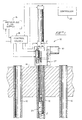
- Figure 1 we schematically illustrate a preferred embodiment of the gap-cutter tool 10 of our invention co-operating with one of several boiler tubes 12 mounted in boiler header 14 and in which the wall is to be machined to provide a longitudinal gap that facilitates subsequent removal of the tube end from its header installation.
- a source of pressurized fluid 16 which may be either pressurized hydraulic fluid or pressurized air
- a group of conventional fluid flow control valves 18 that direct the flow of pressurized fluid between pressurized fluid source 16 and the hereinafter-described actuator devices included in assembly 10
- a conventional controller 20 that regulates the sequential operation of particular fluid flow control valves and that also regulates the sequential operation of the hereinafter-described electrical stepper motor.
- Tool assembly 10 basically is comprised of a tool head subassembly 22 , a clamp subassembly 24 , a cutter head support track subassembly 26 , and a cutter head subassembly 28 , each of which is described hereinafter in greater detail.
- Figures 1 through 5 illustrate the end of tube-end 12 that co-operates with gap-cutter tool assembly 10 as extending beyond the free end of clamp subassembly 24 .
- Assembly 10 will function in a satisfactory manner as hereinafter explained if the free end of subassembly 24 projects beyond the end of tube-end 12 , it only being necessary that the length of tube gap to be machined is within the range of the apparatus cutter head subassembly cutting stroke.
- Tool head subassembly 22 essentially consists of a rigid adaptor block 30 which initially is installed in contacting relation with the cut tube end 12 that is to be provided with the machined gap, which in part functions as a housing to contain and support several different interiorly-mounted subassembly component parts, and which also supports several different exteriorly-located component parts.
- a rigid adaptor block 30 Securely joined to adaptor block 30 and at right-angles to the adaptor block surface that contacts the end surface of boiler cut tube end 12 are rigid and spaced-apart fixed guide rail elements 34 and 36 .
- Slide member 32 structurally a part of the hereinafter-described cutter head support track sub-assembly, slidably dovetails with cross guide ways 38 and 40 provided in adaptor block 30 , supports or carries conventional double-acting, pressurized fluid actuator 42 , and has an oversize interior bore 44 through which the piston rod 46 of actuator 42 passes.
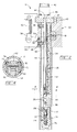
- Internal compression springs 48 are provided in tool head subassembly 22 and are arranged so that their lower ends bear against upper surfaces of the hereinafter described cutter head support track member. See Figure 2.
- a double-acting clamp actuator element 50 which may be of a type that utilizes compressed air as a power source, and conventional electrical stepper motor 52 .
- a clamp drive linkage comprised of clamp arm 54 which is connected to the piston rod 56 of actuator 50 , which is pivoted about pin 58 , and which has an opposite end hole or bore 60 that co-operates with a rail drive pin element of clamp subassembly 24 .
- adaptor block 30 preferably included within the interior of adaptor block 30 are the gear train 61 , which operationally connects stepper motor 52 to cutter support subassembly 26 , and pivoted clamp locking blades 62 ( Figure 5) that are biased toward a non-clamping condition by interior compression springs 64 .
- the ends of clamp locking blades 62 that project from within adaptor block 30 function as movable friction points that selectively contact the interior surface of tube end 12 when pivoted by the sliding action of a clamp rail and its included ramp surface in clamp subassembly 24 ).
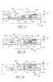
- the tool clamp subassembly 24 is basically comprised of a pair of elongated and longitudinally movable clamp side rails 70 and 72 that each have a segmental cross-section configuration, that are slidably inserted at their head ends into a corresponding recess in adaptor block 30 , and that are interconnected into a unitary structure at their other ends by mechanical actuator housing 74 and co-operating screw-type fasteners 75 .
- Each such clamp rail has a longitudinally intermediate ramp surface 78 that co-operates with a respective one of the clamp locking blades 62 incorporated into tool head subassembly 22 .
- clamp rail 70 is provided adjacent its extreme opposite mechanical actuator 74 with a drive pin 80 that is engaged with the bore 60 of pivoted clamp arm 54 that is included in tool head subassembly 22 .
- the body of mechanical actuator 74 includes a pair of elongated slots 82 in which through-pin element 76 slides as a consequence of longitudinal movement of clamp rails 70 and 72 by operation of clamp actuator 50 . Movement of through-pin 76 within slots 82 (see Figure 3) functions to first move actuator compression spring 84 , actuator interior cone element 86 , and the included three radially-slidable clamp pins 88 , and causes the ends of those pins to securely contact the interior wall surface of cut tube length 12 . Such clamping action involving radially-slidable clamp pins 88 occurs simultaneously with the clamping action induced into clamp locking blades 52 against the compression of blade spring element 54 .
- clamp pins 88 function as movable friction points that selectively engage the inner surface of boiler tube-end 12 when actuated.
- mechanical actuator element 74 can be modified to function with clamp locking blades similar to locking blades 62 in lieu of the radially-oriented clamp pin element 88 .
- subassembly 24 becomes clamped at its actuator 74 end before clamping is completed at its adaptor block 30 end, as in the case where the tube interior diameter of the actuator 74 end is significantly smaller than the tube interior diameter at the adaptor block 30 end, the required additional longitudinal movement of clamp rails 70 and 72 can occur because compression spring 84 will be further compressed and thereby "take up" the additional movement without further moving radial clamp pins 88 .
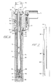
- clamp subassembly 24 in its installed position may be situated either completely within the interior limits of the boiler tube end 12 that is to be machined (Figure 1), or alternatively, at least throughout the extent of the cut that is to be made if installed in a materially shorter tube end 12 ( Figure 2).
- the radial clamp pins 88 are useful in assuring centering the axis of apparatus assembly 10 within the tube end, they need not make contact with a tube end interior in order to adequately clamp assembly 10 in position during an apparatus cutting stroke because the tube reaction force during cutting tends to more forcefully draw apparatus 10 into the tube interior.
- the cutter head support track subassembly 24 provided in gap-cutter tool assembly 10 is basically comprised of an elongated cutter head support member 90 that has an "H"-configured cross-section (see Figure 4) and that has an elevationally adjustable position relative to the interior of cut tube-end 12 .
- Cutter head support member 90 is rigidly joined to and carried by slide member 32 and is positioned in a manner whereby the support web that interconnects the support member spaced-apart upstanding legs of the "H"-configuration is oriented at right angles to the longitudinal axes of adaptor block cross-ways 38 and 40 .
- the previously-described compression springs 48 bear against the uppermost extremes of the spaced-apart upstanding legs of cutter support member 90 .
- Changes in lateral (elevational) position of cutter support member 90 within tube-end 12 are achieved by relative movement between multi-ramp wedge shoe 92 , which shoe is fastened to the underside of the interconnect web of cutter support member 90 , and complementary-configured multi-ramp wedge rack element 94 .
- Wedge rack element 94 has a toothed rack 96 adjacent one end, and that toothed rack co-operates with the gear train 61 that is powered by electrical stepper motor 18 .
- cutter support member 90 is positioned at its elevationally lowest position.
- Figure 3 illustrates support member 90 at an elevationally higher position than in Figure 2 - such as occurs when an individual longitudinal interior gap cut is being made in the wall of tube end 12 by apparatus 10 .
- Upward movement of cutter support member 90 resulting from longitudinal displacement of multi-ramp rack element 94 by stepper motor 52 and gear train 61 does not involve any movement of co-operating fixed rails 34 and 36 .
- cutter support member 90 An important feature of cutter support member 90 is the pair of oppositely-positioned guide track elements 98 which are preferably machined as a slot in each of the upstanding legs of cutter support member 90 .
- Each guide track element 98 has an elongated straight-run portion 100 and a connected, downwardly inclined, "dog-leg" portion 102 . See Figure 7.
- the hereinafter described tool articulated cutter head subassembly 28 co-operates directly with guide track elements 98 , and is elevationally being advanced toward or withdrawn from contact with a wall of tube-end 12 whenever the elevational position of cutter support member 90 is being changed.
- guide track elements 98 of apparatus support track subassembly 26 for use in cases wherein the tube mounting bore of boiler header 14 incorporates a flare or bell configuration to facilitate swaging the tube end in place during boiler tube installation.
- a substitute cutter support member having guide track elements with an alternate profile is provided. More specifically, the ends of guide track straight-run portions 100 nearest tool head subassembly 22 are in those situations each provided with a flare or bell contour that corresponds to the end flare or bell profile of the boiler header mounting bore in which boiler tube-end 12 is installed.
- subassembly 28 is an articulated subassembly that is basically comprised of a clevis body portion 110 , a tang body portion 112 , and three trunnion-like, support axle elements 114 , 116 , and 118 .
- support axle element 114 engages bore 120 of clevis body portion 110 of subassembly 28 and each end of that axle element projects outside clevis body portion 110 a sufficient distance to properly engage and co-operate with guide tracks 98 provided in cutter support member 90 .
- axle element 118 co-operates with a bore or through-hole 122 provided in tang body portion 112 of subassembly 28 and its projected ends also co-operate with guide track elements 98 of cutter support member 90 .
- Axle element 116 co-operates with the through-bore 124 of tang body portion 112 and with the identical elongate slot elements 126 provided in the legs of clevis body portion 110 .
- subassembly 28 is provided with a threaded bore 128 in one end of tang body portion 112 for cooperation with a correspondingly threaded end of actuator piston rod 46 , and with recesses 130 and 132 and mounting bores 134 and 136 in clevis body portion 110 for receiving conventional cutter tool bit holder inserts and their included cutter tool bits.
- the elongate slots 126 provided in the legs of the subassembly clevis body portion 110 have a "dog-leg" elevational configuration comprised of two portions 140 and 142 .
- Slot portion 142 preferably has an axial orientation that is rotated approximately 30° from the axial rotation of slot portion 140 . Such orientation departure is provided so that axle element 116 will impart a degree of rotation to clevis body portion 110 about the axis of axle element 114 during the apparatus operating return stroke.
- FIG. 10 Another and non-articulated form of cutter subassembly 128 that may advantageously be utilized in assembly 10 is illustrated in Figure 10.
- the cutter body is comprised only of an elongated clevis body portion 110 similar to the corresponding element illustrated in Figures 8 and 9.
- the Figure 10 trunnion-like axle element 116 is essentially a pin connection carried directly by the end of piston rod element 46 of actuator 42 rather than by a cutter head tang body portion such as element 112 of Figures 8 and 9.
- axle element 116 engages end-portions 140 ( Figure 9) of elongate slot elements 126 so that clevis body portion 110 is positioned with the tip of the cutter head included tool bit elevated a distance "A" above the upper surface of tang body portion 112 .
- each of three subassembly axle elements is engaged with the straight-line portions 100 of opposed guide track elements 98 .
- axle element 116 engages the end region 142 of clevis body portion slot elements 126 whereby clevis body portion is rotated about axle element 114 so that the tip of the cutter head included tool bit is elevated a smaller distance "B" above the upper surface of the subassembly tang body portion 112 .
- the distance "B” achieved during tool assembly operation is approximately 0.030 inch less that the distance "A" thus providing more than adequate clearance for the tool bit during the apparatus return stroke.
- Subassembly 28 is subsequently moved to an end-of-return stroke condition to facilitate the making of an adjustment to the elevational position of the cutter head subassembly 28 for the next succeeding cut.
- the tip of the subassembly included tool bit element (or elements if more than one cutter tool bit is utilized) is positioned at an elevation lower than that illustrated in connection with Figure 11. See Figure 13. More specifically, the new tool bit tip is positioned a distance "C" above the upper surface of subassembly tang body portion 112 .
- the distance "C" was approximately 0.090 inches below the Figure 10 position thus affording a more than adequate elevational height adjustment zone for elevating cutter support member 90 to its next succeeding position by the actuation of stepper motor 52 and co-operating wedge rack element 94 .
- Boiler tubes to which the present invention has had widest application generally are in the size range of from 2 inches diameter to 4 inches diameter, and with wall thicknesses ranging approximately from 0.095 to 0.180 inches.
- An operating hydraulic pressure of approximately 2,000 pounds per square inch has proven satisfactory with a cutting head reciprocating frequency of 60 cycles per minute being utilized. (Hydraulic actuator strokes may range to approximately 7 to 8 inches).
- the pulsed actuation of the apparatus stepper motor to reposition a multi-ramp wedge rack with included 30° inclined ramps has been controlled to move the cutter head subassembly and included tool cutting bits radially incrementally toward the tube end wall metal in increments of approximately 0.006 inches per completed cutting stroke.
- gap-cutter tool assembly 10 The procedural steps for the use of gap-cutter tool assembly 10 are prefaced with the remark that it is not necessary that the candidate boiler tube for removal and replacement be initially cut near its boiler header mounting bore for the reason that the disclosed and claimed gap cutter tool assembly functions equally well when installed and co-operating with either a short tube section or a comparatively long tube section.
- the apparatus clamp subassembly functions properly even though there is no tube interior surface for the clamp pins or clamp blades located farthest from the tool head to contact; the clamp blades situated near the apparatus adaptor block when alone contacting the tube length interior surface, either with or without surface scale, provide excellent apparatus centering and anchoring for the subsequent gap-machining steps.
- the clamp subassembly through its motion take-up compression spring 84 enables the tool assembly to be satisfactorily centered and anchored at the tube header end and even though the tube diameter near the clamp remote end is appreciably smaller due to substantial scaling.
- stepper motor 52 is sequenced by controller 20 to elevate cutter head support track subassembly 26 to its initial cut elevation through the co-operative interaction of wedge rack element 94 and wedge shoe element 94 .
- a depth of cut of approximately 0.006 inch, and the elevation of cutter head support track assembly 26 is set accordingly.
- pressurized fluid ported to actuator 42 causes cutter head assembly to move through a cutting stroke along straight-line portion 100 of guide tracks 98 , and then through a return stroke wherein the cutter head tool tip is lowered by as much as approximately 0.030 inch due to the engagement of trunnion axle element 116 engaging the slot ends 142 in cutter head body portion 110 .
- the tip of the cutter head tool bit insert is further lowered, e.g., by an additional approximately 0.060 inch, to its end-of-return stroke position.
- the system stepper motor 52 is then sequenced to elevate cutter head support track subassembly 26 by the depth of the next cut, e.g. approximately 0.006 inch.
- the cycle of cutting stroke, return stroke, and cutter head elevating steps is then repeated until the total depth of cut in tube end 12 has been achieved.
- clamp actuator 50 is deactivated, and tool assembly 10 is withdrawn from engagement with tube end 12 to facilitate the subsequent lateral or circumferential compression of the tube end and its withdrawal from within tube header 14 .
Landscapes
- Engineering & Computer Science (AREA)
- Physics & Mathematics (AREA)
- Thermal Sciences (AREA)
- Mechanical Engineering (AREA)
- General Engineering & Computer Science (AREA)
- Drilling And Boring (AREA)
- Milling, Broaching, Filing, Reaming, And Others (AREA)
- Turning (AREA)
Applications Claiming Priority (2)
| Application Number | Priority Date | Filing Date | Title |
|---|---|---|---|
| US08/934,818 US5893209A (en) | 1997-09-22 | 1997-09-22 | Apparatus for effecting boiler tube removal |
| US934818 | 1997-09-22 |
Publications (2)
| Publication Number | Publication Date |
|---|---|
| EP0903537A2 true EP0903537A2 (fr) | 1999-03-24 |
| EP0903537A3 EP0903537A3 (fr) | 2002-02-27 |
Family
ID=25466112
Family Applications (1)
| Application Number | Title | Priority Date | Filing Date |
|---|---|---|---|
| EP98630051A Withdrawn EP0903537A3 (fr) | 1997-09-22 | 1998-09-11 | Méthode et appareil d'enlèvement d'un tube de chaudière |
Country Status (3)
| Country | Link |
|---|---|
| US (1) | US5893209A (fr) |
| EP (1) | EP0903537A3 (fr) |
| CA (1) | CA2247488C (fr) |
Cited By (4)
| Publication number | Priority date | Publication date | Assignee | Title |
|---|---|---|---|---|
| EP0864810A3 (fr) * | 1997-03-10 | 2001-09-12 | Advanced Cutting Technologies, Inc. | Méthode et dispositif d'enlèvement d'un tube de chaudière |
| ITMI20101228A1 (it) * | 2010-07-05 | 2012-01-06 | Maus Italia F Agostino & C S A S | Dispositivo e metodo di snervamento e taglio di un tronchetto di tubo per agevolarne l'estrazione da un foro |
| JP2016161236A (ja) * | 2015-03-03 | 2016-09-05 | 三菱日立パワーシステムズ株式会社 | 伝熱管の応急処置具及び伝熱管の応急処置方法 |
| US9643827B2 (en) | 2014-10-06 | 2017-05-09 | Phil Madron | Fire tube implement, system, and method |
Families Citing this family (15)
| Publication number | Priority date | Publication date | Assignee | Title |
|---|---|---|---|---|
| US6182354B1 (en) | 1999-10-12 | 2001-02-06 | Advanced Cutting Technologies, Ltd. | Boiler tube segment and bend tool |
| US6209181B1 (en) | 1999-10-12 | 2001-04-03 | Advanced Cutting Technologies, Ltd. | Boiler tube flare-end segment peeler tool |
| US6205632B1 (en) | 1999-10-12 | 2001-03-27 | Advanced Cutting Technologies, Ltd. | Boiler tube flared-end compression tool |
| EP1096199A2 (fr) | 1999-10-27 | 2001-05-02 | Advanced Cutting Technologies, Ltd. | Méthode d'enlèvement d'un tube de chaudière |
| SE0202488D0 (sv) * | 2002-08-22 | 2002-08-22 | Alstom Switzerland Ltd | Method of dismantling a cooling tube in a stator tooth and tool used therefor |
| US7305756B2 (en) * | 2004-04-22 | 2007-12-11 | Barcock & Wilcox Canada Ltd. | Tube extracting device |
| US7194800B2 (en) * | 2004-06-07 | 2007-03-27 | Babcick & Wilcox Canada, Ltd. | Internal tube extracting device with a cylindrical collapsing wedge |
| US7146716B2 (en) * | 2004-06-08 | 2006-12-12 | Babcock & Wilcox Canada Ltd. | External tube extraction device with a cylindrical collapsing wedge |
| US7168143B2 (en) * | 2004-06-30 | 2007-01-30 | Babcock & Wilcox Canada Ltd. | External tube deforming extraction device |
| US7322090B2 (en) * | 2005-01-19 | 2008-01-29 | Babcock & Wilcox Canada Ltd. | Explosive tube removal device |
| US7657985B2 (en) * | 2006-03-08 | 2010-02-09 | Mcclure Mark W | Modified boiler wall tube tool |
| US8348253B2 (en) * | 2006-03-08 | 2013-01-08 | Mcclure Mark W | Modified boiler wall tube tool |
| US20070296133A1 (en) * | 2006-06-21 | 2007-12-27 | Mcclure Mark W | Modified Boiler Wall Tube Tool Having Inhibiting Means |
| US11118780B2 (en) | 2015-11-05 | 2021-09-14 | Charger Energy Services, Llc | System and method for removing and replacing fire-tubes |
| US20230084823A1 (en) * | 2021-09-14 | 2023-03-16 | Charger Energy Services, Llc | System and method for removing and replacing fire-tubes |
Family Cites Families (13)
| Publication number | Priority date | Publication date | Assignee | Title |
|---|---|---|---|---|
| GB579756A (en) * | 1945-01-12 | 1946-08-14 | Griscom Russell Co | Method of removing defective tubes from tube sheets |
| US2507201A (en) * | 1946-09-17 | 1950-05-09 | Evans Clair Otto | Tool for removing tubes from tube sheets |
| US3628246A (en) * | 1968-09-06 | 1971-12-21 | Carrier Corp | Apparatus for tube removal |
| GB8404922D0 (en) * | 1984-02-24 | 1984-03-28 | Babcock Power Ltd | Tool head |
| US4633555A (en) * | 1985-04-10 | 1987-01-06 | Legge Gerald A | Method for cutting tube-walls |
| US5044075A (en) * | 1986-10-07 | 1991-09-03 | Sma Controls, Inc. | Boiler repair |
| US4830551A (en) * | 1986-10-07 | 1989-05-16 | Sma Controls, Inc. | Boiler repair |
| US4979294A (en) * | 1989-07-17 | 1990-12-25 | The Dayton Power & Light Company | Boiler tube repair method |
| US5033347A (en) * | 1989-08-25 | 1991-07-23 | Hillestad Tollief O | Boiler tube cutting apparatus |
| US5356248A (en) * | 1993-11-17 | 1994-10-18 | Hillestad Mark W | Boiler tube bank repair |
| US5626445A (en) * | 1995-01-23 | 1997-05-06 | The United States Of America As Represented By The United States Department Of Energy | Tube cutter tool and method of use for coupon removal |
| US5826334A (en) * | 1997-03-10 | 1998-10-27 | Advanced Cutting Technologies, Inc. | Boiler tube removal method |
| EP1096199A2 (fr) * | 1999-10-27 | 2001-05-02 | Advanced Cutting Technologies, Ltd. | Méthode d'enlèvement d'un tube de chaudière |
-
1997
- 1997-09-22 US US08/934,818 patent/US5893209A/en not_active Expired - Fee Related
-
1998
- 1998-09-11 EP EP98630051A patent/EP0903537A3/fr not_active Withdrawn
- 1998-09-21 CA CA002247488A patent/CA2247488C/fr not_active Expired - Fee Related
Cited By (5)
| Publication number | Priority date | Publication date | Assignee | Title |
|---|---|---|---|---|
| EP0864810A3 (fr) * | 1997-03-10 | 2001-09-12 | Advanced Cutting Technologies, Inc. | Méthode et dispositif d'enlèvement d'un tube de chaudière |
| ITMI20101228A1 (it) * | 2010-07-05 | 2012-01-06 | Maus Italia F Agostino & C S A S | Dispositivo e metodo di snervamento e taglio di un tronchetto di tubo per agevolarne l'estrazione da un foro |
| US9643827B2 (en) | 2014-10-06 | 2017-05-09 | Phil Madron | Fire tube implement, system, and method |
| US9656841B2 (en) | 2014-10-06 | 2017-05-23 | Phil Madron | Fire tube implement, system, and method |
| JP2016161236A (ja) * | 2015-03-03 | 2016-09-05 | 三菱日立パワーシステムズ株式会社 | 伝熱管の応急処置具及び伝熱管の応急処置方法 |
Also Published As
| Publication number | Publication date |
|---|---|
| US5893209A (en) | 1999-04-13 |
| CA2247488C (fr) | 2004-10-26 |
| EP0903537A3 (fr) | 2002-02-27 |
| CA2247488A1 (fr) | 1999-03-22 |
Similar Documents
| Publication | Publication Date | Title |
|---|---|---|
| US5893209A (en) | Apparatus for effecting boiler tube removal | |
| US5826334A (en) | Boiler tube removal method | |
| US6161273A (en) | Method and apparatus for forming rivet joints | |
| JP2753125B2 (ja) | チューブ膨張を行う方法および装置 | |
| US4915181A (en) | Tubing bit opener | |
| KR100487836B1 (ko) | 보어구멍의에지용디버어링공구 | |
| JP5133353B2 (ja) | バリ取り工具 | |
| US7556187B2 (en) | Method of manufacturing cylindrical body, friction stir welding method, and friction stir welding device | |
| CN102896356B (zh) | 用于加工薄壁筒件的内钻孔装置 | |
| CN105364515A (zh) | 可调节夹具机构 | |
| AU602841B2 (en) | Method and apparatus for stitch-machining deep cavities in metal workpieces | |
| KR100887783B1 (ko) | 보일러 튜브 절단 장치용 마찰 라이너 가이드 레일 | |
| CA1048319A (fr) | Methode et dispositif de faconnage d'une forme aerodynamique | |
| CA3040358A1 (fr) | Machine de forage profond, outil destine a une machine de forage profond et tube en fonte centrifugee | |
| US7815094B2 (en) | Method of manufacturing cylindrical body, and friction stir welding method | |
| US20040253914A1 (en) | Machine tool with fluid actuated helical adjustment of abrasive elements | |
| US6309145B1 (en) | Portable machine tool for conditioning header tube openings for butt-welding tubes | |
| KR20020020844A (ko) | 공작물을 절삭 및 디버링 가공하는 공구 및 방법 | |
| US4002107A (en) | Disposable fluid actuator | |
| US7520705B2 (en) | Method for grooving the bore of a tube and grooving tool-holder | |
| JP3830161B2 (ja) | チューブ端の拡口機械 | |
| US7273113B2 (en) | Reversible penetrating machine with a differential air distributing mechanism | |
| US4964328A (en) | Notching blade assembly | |
| EP0234920B1 (fr) | Procédé pour remplacer les bouts de tuyaux d'un échangeur thermique | |
| CA1092402A (fr) | Mecanisme de traction d'une broche |
Legal Events
| Date | Code | Title | Description |
|---|---|---|---|
| PUAI | Public reference made under article 153(3) epc to a published international application that has entered the european phase |
Free format text: ORIGINAL CODE: 0009012 |
|
| AK | Designated contracting states |
Kind code of ref document: A2 Designated state(s): AT BE CH CY DE DK ES FI FR GB GR IE IT LI LU MC NL PT SE Kind code of ref document: A2 Designated state(s): DE FR GB IT SE |
|
| AX | Request for extension of the european patent |
Free format text: AL;LT;LV;MK;RO;SI |
|
| 17P | Request for examination filed |
Effective date: 19990706 |
|
| PUAL | Search report despatched |
Free format text: ORIGINAL CODE: 0009013 |
|
| AK | Designated contracting states |
Kind code of ref document: A3 Designated state(s): AT BE CH CY DE DK ES FI FR GB GR IE IT LI LU MC NL PT SE |
|
| AX | Request for extension of the european patent |
Free format text: AL;LT;LV;MK;RO;SI |
|
| RIC1 | Information provided on ipc code assigned before grant |
Free format text: 7F 22B 37/58 A, 7B 23D 21/02 B |
|
| AKX | Designation fees paid |
Free format text: DE FR GB IT SE |
|
| 17Q | First examination report despatched |
Effective date: 20070831 |
|
| STAA | Information on the status of an ep patent application or granted ep patent |
Free format text: STATUS: THE APPLICATION IS DEEMED TO BE WITHDRAWN |
|
| 18D | Application deemed to be withdrawn |
Effective date: 20080111 |