EP0903516A1 - Différentiel à glissement limité et assemblage perfectionné du boítier dudit différentiel - Google Patents
Différentiel à glissement limité et assemblage perfectionné du boítier dudit différentiel Download PDFInfo
- Publication number
- EP0903516A1 EP0903516A1 EP98117003A EP98117003A EP0903516A1 EP 0903516 A1 EP0903516 A1 EP 0903516A1 EP 98117003 A EP98117003 A EP 98117003A EP 98117003 A EP98117003 A EP 98117003A EP 0903516 A1 EP0903516 A1 EP 0903516A1
- Authority
- EP
- European Patent Office
- Prior art keywords
- defining
- housing
- differential
- endcap
- gear
- Prior art date
- Legal status (The legal status is an assumption and is not a legal conclusion. Google has not performed a legal analysis and makes no representation as to the accuracy of the status listed.)
- Withdrawn
Links
- 229910000831 Steel Inorganic materials 0.000 claims abstract description 7
- 239000010959 steel Substances 0.000 claims abstract description 7
- 230000007246 mechanism Effects 0.000 claims description 22
- 230000009471 action Effects 0.000 claims description 5
- 238000000034 method Methods 0.000 description 8
- 230000008569 process Effects 0.000 description 6
- 238000003466 welding Methods 0.000 description 5
- 229910001018 Cast iron Inorganic materials 0.000 description 4
- 230000008901 benefit Effects 0.000 description 4
- 238000005266 casting Methods 0.000 description 4
- 210000005069 ears Anatomy 0.000 description 4
- 238000003754 machining Methods 0.000 description 4
- 238000004519 manufacturing process Methods 0.000 description 4
- 230000004075 alteration Effects 0.000 description 2
- 239000011324 bead Substances 0.000 description 2
- 238000012986 modification Methods 0.000 description 2
- 230000004048 modification Effects 0.000 description 2
- 230000000750 progressive effect Effects 0.000 description 2
- 230000009467 reduction Effects 0.000 description 2
- JJLJMEJHUUYSSY-UHFFFAOYSA-L Copper hydroxide Chemical compound [OH-].[OH-].[Cu+2] JJLJMEJHUUYSSY-UHFFFAOYSA-L 0.000 description 1
- 238000010276 construction Methods 0.000 description 1
- 230000004069 differentiation Effects 0.000 description 1
- 108010036050 human cationic antimicrobial protein 57 Proteins 0.000 description 1
- 238000003780 insertion Methods 0.000 description 1
- 230000037431 insertion Effects 0.000 description 1
- 230000013011 mating Effects 0.000 description 1
- 239000003607 modifier Substances 0.000 description 1
- 239000007787 solid Substances 0.000 description 1
Images


Classifications
-
- F—MECHANICAL ENGINEERING; LIGHTING; HEATING; WEAPONS; BLASTING
- F16—ENGINEERING ELEMENTS AND UNITS; GENERAL MEASURES FOR PRODUCING AND MAINTAINING EFFECTIVE FUNCTIONING OF MACHINES OR INSTALLATIONS; THERMAL INSULATION IN GENERAL
- F16H—GEARING
- F16H48/00—Differential gearings
- F16H48/20—Arrangements for suppressing or influencing the differential action, e.g. locking devices
- F16H48/22—Arrangements for suppressing or influencing the differential action, e.g. locking devices using friction clutches or brakes
-
- F—MECHANICAL ENGINEERING; LIGHTING; HEATING; WEAPONS; BLASTING
- F16—ENGINEERING ELEMENTS AND UNITS; GENERAL MEASURES FOR PRODUCING AND MAINTAINING EFFECTIVE FUNCTIONING OF MACHINES OR INSTALLATIONS; THERMAL INSULATION IN GENERAL
- F16H—GEARING
- F16H48/00—Differential gearings
- F16H48/06—Differential gearings with gears having orbital motion
- F16H48/08—Differential gearings with gears having orbital motion comprising bevel gears
- F16H2048/085—Differential gearings with gears having orbital motion comprising bevel gears characterised by shafts or gear carriers for orbital gears
-
- F—MECHANICAL ENGINEERING; LIGHTING; HEATING; WEAPONS; BLASTING
- F16—ENGINEERING ELEMENTS AND UNITS; GENERAL MEASURES FOR PRODUCING AND MAINTAINING EFFECTIVE FUNCTIONING OF MACHINES OR INSTALLATIONS; THERMAL INSULATION IN GENERAL
- F16H—GEARING
- F16H48/00—Differential gearings
- F16H48/38—Constructional details
- F16H2048/382—Methods for manufacturing differential gearings
-
- Y—GENERAL TAGGING OF NEW TECHNOLOGICAL DEVELOPMENTS; GENERAL TAGGING OF CROSS-SECTIONAL TECHNOLOGIES SPANNING OVER SEVERAL SECTIONS OF THE IPC; TECHNICAL SUBJECTS COVERED BY FORMER USPC CROSS-REFERENCE ART COLLECTIONS [XRACs] AND DIGESTS
- Y10—TECHNICAL SUBJECTS COVERED BY FORMER USPC
- Y10T—TECHNICAL SUBJECTS COVERED BY FORMER US CLASSIFICATION
- Y10T74/00—Machine element or mechanism
- Y10T74/21—Elements
- Y10T74/2186—Gear casings
Definitions
- the present invention relates to differentials, and more particularly, to an improved design for a differential housing assembly.
- Limited slip differentials of the type which can utilize the present invention typically include a gear case or differential housing defining a gear chamber, and disposed therein, a differential gear set.
- a clutch pack is typically disposed between the gear set and the differential housing, such that the clutch pack is operable to retard or even prevent relative rotation between the gear case and the output gears (side gears) of the gear set.
- the differential housing has comprised a cast iron member, requiring a substantial amount of machining of various surfaces, diameters, etc.
- the tensile strength of cast iron is somewhat limited, such that a load bearing member like a differential housing must comprise a fairly hefty casting, in order to be able to transmit the types of loads to which differentials are typically subjected.
- the need for a fairly sturdy housing casting is especially true in view of the need for access windows, through which the various gears and friction discs are inserted into the housing.
- a differential gear mechanism of the type including a gear case defining an axis of rotation and a gear chamber.
- a differential gear means is disposed in the gear chamber including at least one input gear and first and second output gears.
- the gear case includes a first end cap defining a first hub portion disposed adjacent the first output gear and a housing defining a second hub portion disposed adjacent the second output gear.
- the improved differential gear mechanism is characterized by the first end cap defining a plurality of openings arranged generally circumferentially about the axis of rotation.
- the housing defines a plurality of tabs adapted to be received in the openings defined by the first end cap.
- a means fixedly attaches the tabs and the housing relative to the openings and the first end cap.
- FIG. 1 is an axial cross-section of a limited slip differential of the type with which the present invention may be utilized.
- the construction and operation of the limited slip differential illustrated in FIG. 1 may be better understood by reference to U.S. Patent No. 3,648,545, assigned to the assignee of the present invention, and incorporated herein by reference.
- the differential gear mechanism includes a gear case (or differential housing) 11 which defines therein a gear chamber, generally designated 13.
- Torque input to the differential mechanism is typically by means of an input ring gear 14 which may be attached to a mounting flange 15 of the gear case 11 by any suitable means, such as by a plurality of bolts 16.
- a differential gear set including a pair of input pinion gears 17, which are rotatably supported on a pinion shaft 19.
- the pinion shaft 19 has been secured relative to the gear case 11 by any suitable means, such as a locking pin.
- a circular groove 21 Disposed adjacent each axial end of the pinion shaft 19 is a circular groove 21, of the type which is adapted to receive a snap ring or C-clip or other similar, suitable retaining member.
- the pinion gears 17 are in meshing engagement with a pair of side gears 23 and 25.
- the side gears 23 and 25 define sets of internal, straight splines 27 and 29, respectively, which are adapted to be in splined engagement with mating external splines of a pair of axle shafts (not shown).
- the gear case 11 includes an end cap 31, including an annular hub portion 33, and a housing member 35, including an annular hub portion 37.
- the hub portions 33 and 37 may have mounted thereon a pair of bearing sets (not shown herein) which are used to provide rotational support for the differential mechanism 10 relative to an outer differential housing (also not shown herein).
- the limited slip differential 10 is provided with a clutch pack, generally designated 41, and a clutch pack, generally designated 43.
- the clutch pack 41 includes several friction discs 45 which are in engagement with the gear case 11, and more specifically with the housing member 35, and several friction discs 46 which are in splined engagement with the side gear 23.
- the clutch pack 43 includes several friction discs 47 which are in engagement with the housing member 35, and several friction discs 48 which are in splined engagement with the side gear 25.
- the end cap 31 defines a plurality of openings.
- the end cap 31 comprises a stamped steel member having a periphery 51, inboard of the mounting flange 15 (see both FIGS. 1 and 2) which, as may best be seen in FIG. 2, is both somewhat circular and somewhat squared.
- the end cap 31 has the mounting flange 15 formed integrally therewith, such that the various openings to be described may be pierced or stamped during the stamping of the end cap 31.
- the end cap 31 defines upper and lower straight openings 52 and 53, respectively, and four arcuate openings 54. It should be understood by those skilled in the art that the particular configuration of the openings 52, 53 and 54 it is not an essential feature of the invention, but typically, the openings will be arranged generally circumferentially about the axis of rotation A, for reasons which will become apparent subsequently. It should be understood that references hereinafter, and in the appended claims, to the openings being arranged circumferentially does not require that the openings be in a truly circular pattern, but instead, includes any sort of arrangement around the axis of rotation A, as shown in FIG. 2, in which the openings surround the axis of rotation A.
- the housing member 35 may comprise a one-piece steel stamping, which is initially stamped substantially as a flat, planar member as shown in FIG. 3, and then subsequently formed to its final configuration as shown in FIG. 4.
- the housing member 35 includes an end cap portion 57, including the annular hub portion 37. Attached to the end cap portion 57 is a pair of oppositely disposed upper and lower flat portions 59 and 61, respectively.
- Each of the flat portions 59 and 61 defines a circular opening 63 through which the respective end of the pinion shaft 19 extends, upon assembly of the differential mechanism 10.
- the upper flat portion 59 includes, toward its axial end a pair of side portions 65, which are ultimately formed as shown in FIGS. 4 and 5.
- the lower flat portion 61 includes a pair of side portions 67 which are also ultimately formed as shown in FIGS. 4 and 5.
- the upper flat portion 59 defines, at its axial end opposite the hub portion 37, an axial projection (or tab) 72.
- the lower flat portion 61 defines an axial projection (or tab) 73.
- each of the side portions 65 and each of the side portions 67 defines an axial projection (or tab) 74, the tabs 74 being flat when the housing member 35 is initially stamped (as shown in FIG. 3), but the tabs 74 eventually having the same arcuate configuration as the respective side portions 65 and 67, after the stamping is formed to its final configuration as shown in FIG. 4.
- the housing member 35 After the housing member 35 is stamped, as shown in FIG. 3, it must then be formed into the final configuration, as shown in FIG. 4.
- the particular forming process is not an essential feature of the present invention, but in the subject embodiment, a "progressive" die arrangement is used.
- progressive dies transform a work piece, such as the flat piece of FIG. 3, into the final configuration of FIG. 4 in a series of steps, in which each step performs a part of the overall forming process.
- the side portions 65 and 67 would be bent "upward" out of the plane of FIG. 3 to the shape (relative to the flat portions 59 and 61) shown in FIG. 5.
- the flat portions 59 and 61 would be bent upward out of the plane of FIG. 3 to provide the overall general U-shape defined by the end cap 57 and the flat portions 59 and 61.
- each pair of side portions 65 and 67 defines therebetween an axially extending gap 75 which opens into an access window 77 (only one of which is shown in FIG. 4).
- the access windows 77 are utilized during assembly of the differential mechanism 10 to insert within the gear case 11 the pinion gears, the side gears and the clutch packs. It is one advantage of the present invention that, because the stamping comprising the housing member 35 has greater tensile strength than a typical casting, the access windows 77 may be relatively larger than in prior art differentials, thus facilitating the assembly process.
- the gear case 11 is assembled by inserting the straight tabs 72 and 73 into the straight openings 52 and 53, respectively, while at the same time inserting each of the arcuate tabs 74 into its respective arcuate opening 54.
- this insertion step is performed with the assistance of appropriate fixturing so that each tab is in alignment with its respective opening.
- the use of one or more fixtures is also important to make sure that the annular hub portions 33 and 37 are substantially coaxial, after the tabs are inserted in the openings.
- This assembled condition is represented in FIG. 1 in which the straight tabs 72 and 73 are visible in their openings 52 and 53, respectively
- the assembly is completed by "fixing” in a permanent manner the tabs 72, 73 and 74 within the openings 52, 53 and 54, respectively.
- the tabs are fixed within the openings by any one of a number of well known welding methods.
- the welding step will be performed from the end cap end of the housing, i.e., from the left end in FIG. 1, so that any weld bead which is formed would be disposed within the opening 52, 53, or 54, as opposed to having a weld bead disposed inside the gear chamber 13, where it could interfere with the placement of the friction discs.
- the fully assembled gear case 11 is chucked on the outside diameters of the hub portions 33 and 37, after which the inside diameters are machined to desired dimension, then the hub portions 33 and 37 are chucked on the inside diameters, while the outside diameters are machined to desired dimension.
- there may be a ring gear pilot diameter associated with the mounting flange 15 which needs to be fairly accurately machined, for reasons which are well known to those skilled in the art.
- an inside surface of each of the flat portions 59 and 61, around the openings 63 typically needs to be machined as a seat for either the pinion gears 17 or for a backup washer disposed between the pinion gear and the adjacent flat surface.
- FIG. 5 one additional advantage of the present invention may be seen.
- the friction discs which are fixed relative to the gear case to be provided with a plurality (typically four) of ears received within corresponding slots formed on the inside of the housing casting.
- hardened wear guards also known as ear clips
- An important benefit of the present invention is that the stamped housing member 35 is able to retain the friction discs 45 and 47, without the need for any sort of clips or guards.
- each disc 45 (and each disc 47 as well) includes a pair of diametrically opposite "ears" 79, each of which defines a straight edge disposed immediately adjacent the flat, interior surface 59s and 61s of the flat portions 59 and 61.
- one or both of the hub portions 33 and 37 may comprise separate pieces.
- the hub portion 37 may comprise a separate member, which is received within an opening in the endcap portion 57.
- the separate hub portion is attached to its respective member by any suitable process such as MIG welding or spin (friction) welding.
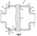
- FIG. 6 illustrates a housing for a limited slip differential which may be substantially identical to the one shown in FIG. 1, but wherein the gear case comprises an alternative embodiment of the invention.
- a gear case generally designated 81, comprising a stamped end cap 83 including an annular hub portion 85, and a housing assembly, comprising a housing member 87, and an end cap 89 including an annular hub portion 91.
- the housing 87 is a cylindrical member (rather than somewhat U-shaped as is the housing member 35.
- the housing 87 comprises a deep drawn steel stamping.
- the end cap 83 defines a plurality of openings, and because the housing 87 is cylindrical, the openings in the end cap 83 are truly arranged in a circular pattern about the axis of rotation A. It should be understood that the particular size, shape and arrangement of openings is not, in and of itself, a critical feature of the invention.
- the end cap 83 defines a plurality of arcuate openings 93, there being a total of six of the openings 93 shown in FIG. 7 At the left end (in FIG.
- the cylindrical stamping includes a plurality of projections or tabs 95 which preferably correspond in shape and location to the openings 93, in the same manner as in the primary embodiment.
- the tabs may be desirable for the tabs to be smaller than the respective openings, by an amount which is sufficient to insure that all of the tabs fit into the openings simultaneously, without the need to force the parts together. The above is part of the reason to hold the parts in appropriate fixturing as the parts are assembled and welded.
- the housing 87 includes a plurality of tabs 97 which, upon initial drawing of the housing 87 lie in the cylinder of the housing, i.e., extending to the right in FIG. 6.
- the end cap 89 is generally circular, but the outside diameter as seen in FIG. 6 defines a series of notches, each of which is approximately the circumferential width of one of the tabs 97.
- the next step is to place that assembly and the end cap 83 together, in the position shown in FIG. 6, and then fix the tabs 95 within the openings 93. As was the case in the primary embodiment, this is preferably accomplished by means of a suitable welding process. After the entire housing assembly 81 is together as shown in FIG. 6 (but without the pinion shaft 19), the machining described in connection with the primary embodiment would typically be done.
- the present invention provides several embodiments of an improved housing for use with a differential, wherein the housing assembly may comprise stampings, thereby reducing the normal tooling costs associated with the production of cast iron differential housings. It is considered likely that, for most designs, another benefit will be a stronger, but lighter, housing assembly.
Landscapes
- Engineering & Computer Science (AREA)
- General Engineering & Computer Science (AREA)
- Mechanical Engineering (AREA)
- Retarders (AREA)
- General Details Of Gearings (AREA)
Applications Claiming Priority (2)
| Application Number | Priority Date | Filing Date | Title |
|---|---|---|---|
| US933790 | 1997-09-19 | ||
| US08/933,790 US5938558A (en) | 1997-09-19 | 1997-09-19 | Limited slip differential and improved differential housing assembly therefor |
Publications (1)
| Publication Number | Publication Date |
|---|---|
| EP0903516A1 true EP0903516A1 (fr) | 1999-03-24 |
Family
ID=25464510
Family Applications (1)
| Application Number | Title | Priority Date | Filing Date |
|---|---|---|---|
| EP98117003A Withdrawn EP0903516A1 (fr) | 1997-09-19 | 1998-09-08 | Différentiel à glissement limité et assemblage perfectionné du boítier dudit différentiel |
Country Status (6)
| Country | Link |
|---|---|
| US (1) | US5938558A (fr) |
| EP (1) | EP0903516A1 (fr) |
| JP (1) | JPH11148548A (fr) |
| KR (1) | KR19990029865A (fr) |
| CN (1) | CN1212215A (fr) |
| BR (1) | BR9804106A (fr) |
Cited By (5)
| Publication number | Priority date | Publication date | Assignee | Title |
|---|---|---|---|---|
| WO2004053357A1 (fr) * | 2002-12-05 | 2004-06-24 | Ronjo Company, Llc | Mecanisme differentiel pour un vehicule |
| DE102006062200A1 (de) * | 2006-12-22 | 2008-06-26 | Gkn Driveline International Gmbh | Differentialanordnung mit mehrteiligem Differentialkorb und Verfahren zur Herstellung einer Differentialanordnung |
| DE102011007698A1 (de) * | 2011-04-19 | 2012-10-25 | Neapco Europe Gmbh | Differenzial mit integrierter Lagerung der Kronenräder |
| DE102013013737A1 (de) | 2013-08-21 | 2015-02-26 | Sona Blw Präzisionsschmiede Gmbh | Differentialgetriebeanordnung |
| DE102020113361A1 (de) | 2020-05-18 | 2021-11-18 | Elringklinger Ag | Gehäuse zur Aufnahme des Getriebes eines Kegelraddifferentials und Kegelraddifferential |
Families Citing this family (26)
| Publication number | Priority date | Publication date | Assignee | Title |
|---|---|---|---|---|
| US6010424A (en) * | 1998-10-22 | 2000-01-04 | Dana Corporation | Two-piece limited slip differential |
| KR100792941B1 (ko) * | 2001-05-23 | 2008-01-08 | 현대자동차주식회사 | 버스용 시트 마운팅 구조 |
| US7081061B1 (en) | 2002-09-03 | 2006-07-25 | Hydro-Gear Limited Partnership | Hydraulic motor apparatus |
| US6811510B1 (en) | 2002-09-03 | 2004-11-02 | Hydro-Gear Limited Partnership | Hydraulic motor apparatus and vehicle |
| US6811509B1 (en) | 2002-09-03 | 2004-11-02 | Hydro-Gear Limited Partnership | Hydraulic motor apparatus including brake mechanism |
| US6840879B1 (en) | 2002-09-03 | 2005-01-11 | Hydro-Gear Limited Partnership | Hydraulic motor apparatus |
| DE102004015316B4 (de) * | 2004-03-29 | 2012-08-30 | Zf Friedrichshafen Ag | Ausgleichsgetriebe |
| US7367914B2 (en) * | 2005-02-25 | 2008-05-06 | Ronjo Company | Differential housing support member |
| US7485064B2 (en) * | 2005-02-25 | 2009-02-03 | Ronjo Company | Releasable enclosure for differential housing |
| US7232397B2 (en) * | 2005-04-27 | 2007-06-19 | American Axle & Manufacturing, Inc. | Axleshaft retention assembly for differentials and method of assembly |
| US7320659B2 (en) * | 2005-04-29 | 2008-01-22 | American Axle & Manufacturing, Inc. | Differential assembly with semi-elliptical assembly window |
| USD549731S1 (en) * | 2005-10-20 | 2007-08-28 | Dana Corporation | Vehicle differential case |
| EP2137434B9 (fr) * | 2007-04-05 | 2013-05-29 | Neumayer Tekfor Holding GMBH | Differentiel presentant une roue motrice |
| RU2397390C1 (ru) * | 2008-12-31 | 2010-08-20 | Виктор Михайлович Кузеванов | Дифференциал |
| US9080622B2 (en) | 2009-04-03 | 2015-07-14 | Eaton Corporation | Hydraulic coupling having self-adjusting anti-rotation hydraulic fluid path |
| US9403233B2 (en) | 2011-12-16 | 2016-08-02 | Illinois Tool Works Inc. | DC electrode negative rotating arc welding method and system |
| US9511442B2 (en) | 2012-07-27 | 2016-12-06 | Illinois Tool Works Inc. | Adaptable rotating arc welding method and system |
| USD713935S1 (en) | 2013-06-05 | 2014-09-23 | Eaton Corporation | Limited slip differential |
| DE102013109835B4 (de) * | 2013-09-09 | 2017-07-27 | Gkn Automotive Ltd. | Differentialanordnung mit Kupplung |
| US10543551B2 (en) | 2013-09-16 | 2020-01-28 | Illinois Tool Works Inc. | Synchronized rotating arc welding method and system |
| US10953484B2 (en) | 2013-09-16 | 2021-03-23 | Illinois Tool Works Inc. | Narrow groove welding method and system |
| US9752624B2 (en) * | 2014-10-22 | 2017-09-05 | Deere & Company | Tractor/implement PTO connection mechanism |
| US9897188B2 (en) | 2014-12-03 | 2018-02-20 | Musashi Seimitsu Industry Co., Ltd. | Differential device |
| JP6660149B2 (ja) * | 2014-12-03 | 2020-03-04 | 武蔵精密工業株式会社 | 差動装置 |
| JP2016109297A (ja) * | 2014-12-03 | 2016-06-20 | 武蔵精密工業株式会社 | 差動装置 |
| US11946535B2 (en) * | 2022-08-14 | 2024-04-02 | Doubleeagle Industry (China) Limited | Clamp building block differential |
Citations (10)
| Publication number | Priority date | Publication date | Assignee | Title |
|---|---|---|---|---|
| US3906812A (en) * | 1973-03-31 | 1975-09-23 | Aisin Seiki | Locking differential |
| FR2438773A1 (fr) * | 1978-10-14 | 1980-05-09 | Volkswagenwerk Ag | Engrenage differentiel a roues coniques |
| US4221138A (en) * | 1978-01-05 | 1980-09-09 | Stewart Basil G | Differential housing and structure |
| US4455889A (en) * | 1981-10-08 | 1984-06-26 | Mtd Products Inc. | Free floating pinion shaft |
| US4520690A (en) * | 1982-05-14 | 1985-06-04 | Henry Dangel | Inter-axle differential transfer box unit for a four-wheel drive vehicle |
| US4916973A (en) * | 1988-05-20 | 1990-04-17 | General Motors Corporation | Torque biased differential mechanism |
| EP0411812A2 (fr) * | 1989-07-29 | 1991-02-06 | Fuji Jukogyo Kabushiki Kaisha | Différentiel central pour une voiture à quatre roues motrices |
| DE4115304A1 (de) * | 1991-05-10 | 1992-11-12 | Audi Ag | Differential |
| US5248284A (en) * | 1991-10-22 | 1993-09-28 | Fuji Jukogyo Kabushiki Kaisha | System for controlling a central differential of a four-wheel drive motor vehicle |
| DE19524280A1 (de) * | 1995-07-04 | 1997-01-23 | Zexel Torsen Inc | Steuerbares Parallelachsendifferential |
Family Cites Families (12)
| Publication number | Priority date | Publication date | Assignee | Title |
|---|---|---|---|---|
| US2817251A (en) * | 1955-03-10 | 1957-12-24 | Chrysler Corp | Positive drive differential |
| US3264900A (en) * | 1962-06-14 | 1966-08-09 | Powr Lok Corp | Differential |
| US3362258A (en) * | 1964-01-16 | 1968-01-09 | Ray F. Thornton | Locking differential |
| US3648545A (en) * | 1970-05-18 | 1972-03-14 | Easton Corp | Differential clutch mechanism |
| US4612825A (en) * | 1984-08-21 | 1986-09-23 | Auburn Gear | End cap limited slip differential |
| JP2599271B2 (ja) * | 1987-10-15 | 1997-04-09 | 富士重工業株式会社 | 差動制限装置 |
| US5019021A (en) * | 1990-07-02 | 1991-05-28 | Eaton Corporation | Modulating limited slip differential |
| US5404772A (en) * | 1992-11-06 | 1995-04-11 | Dana Corporation | Transmission housing |
| DE4313322C2 (de) * | 1993-04-23 | 2001-08-02 | Porsche Ag | Differential für den Achsantrieb eines Kraftfahrzeuges |
| DE4317073A1 (de) * | 1993-05-21 | 1994-11-24 | Porsche Ag | Differentialgehäuse für den Achsantrieb eines Kraftfahrzeuges |
| EP0683333B1 (fr) * | 1994-05-18 | 1997-10-01 | Dr.Ing.h.c. F. Porsche Aktiengesellschaft | Différentiel pour l'entraînement de l'essieu d'un véhicule motorisé |
| US5791205A (en) * | 1996-08-09 | 1998-08-11 | Meritor Heavy Vehicle Systems, Llc | Anti-rotation spline teeth for differential case |
-
1997
- 1997-09-19 US US08/933,790 patent/US5938558A/en not_active Expired - Fee Related
-
1998
- 1998-09-08 EP EP98117003A patent/EP0903516A1/fr not_active Withdrawn
- 1998-09-16 KR KR1019980038314A patent/KR19990029865A/ko not_active Withdrawn
- 1998-09-18 CN CN98119626.8A patent/CN1212215A/zh active Pending
- 1998-09-18 JP JP10264683A patent/JPH11148548A/ja active Pending
- 1998-09-18 BR BR9804106-1A patent/BR9804106A/pt not_active Application Discontinuation
Patent Citations (10)
| Publication number | Priority date | Publication date | Assignee | Title |
|---|---|---|---|---|
| US3906812A (en) * | 1973-03-31 | 1975-09-23 | Aisin Seiki | Locking differential |
| US4221138A (en) * | 1978-01-05 | 1980-09-09 | Stewart Basil G | Differential housing and structure |
| FR2438773A1 (fr) * | 1978-10-14 | 1980-05-09 | Volkswagenwerk Ag | Engrenage differentiel a roues coniques |
| US4455889A (en) * | 1981-10-08 | 1984-06-26 | Mtd Products Inc. | Free floating pinion shaft |
| US4520690A (en) * | 1982-05-14 | 1985-06-04 | Henry Dangel | Inter-axle differential transfer box unit for a four-wheel drive vehicle |
| US4916973A (en) * | 1988-05-20 | 1990-04-17 | General Motors Corporation | Torque biased differential mechanism |
| EP0411812A2 (fr) * | 1989-07-29 | 1991-02-06 | Fuji Jukogyo Kabushiki Kaisha | Différentiel central pour une voiture à quatre roues motrices |
| DE4115304A1 (de) * | 1991-05-10 | 1992-11-12 | Audi Ag | Differential |
| US5248284A (en) * | 1991-10-22 | 1993-09-28 | Fuji Jukogyo Kabushiki Kaisha | System for controlling a central differential of a four-wheel drive motor vehicle |
| DE19524280A1 (de) * | 1995-07-04 | 1997-01-23 | Zexel Torsen Inc | Steuerbares Parallelachsendifferential |
Cited By (8)
| Publication number | Priority date | Publication date | Assignee | Title |
|---|---|---|---|---|
| WO2004053357A1 (fr) * | 2002-12-05 | 2004-06-24 | Ronjo Company, Llc | Mecanisme differentiel pour un vehicule |
| US6945898B2 (en) | 2002-12-05 | 2005-09-20 | Ronjo Company, Llc | Differential mechanism for a vehicle |
| DE102006062200A1 (de) * | 2006-12-22 | 2008-06-26 | Gkn Driveline International Gmbh | Differentialanordnung mit mehrteiligem Differentialkorb und Verfahren zur Herstellung einer Differentialanordnung |
| DE102006062200B4 (de) * | 2006-12-22 | 2008-12-18 | Gkn Driveline International Gmbh | Differentialanordnung mit mehrteiligem Differentialkorb und Verfahren zur Herstellung einer Differentialanordnung |
| DE102011007698A1 (de) * | 2011-04-19 | 2012-10-25 | Neapco Europe Gmbh | Differenzial mit integrierter Lagerung der Kronenräder |
| DE102013013737A1 (de) | 2013-08-21 | 2015-02-26 | Sona Blw Präzisionsschmiede Gmbh | Differentialgetriebeanordnung |
| DE102013013737B4 (de) * | 2013-08-21 | 2017-07-27 | Sona Blw Präzisionsschmiede Gmbh | Differentialgetriebeanordnung |
| DE102020113361A1 (de) | 2020-05-18 | 2021-11-18 | Elringklinger Ag | Gehäuse zur Aufnahme des Getriebes eines Kegelraddifferentials und Kegelraddifferential |
Also Published As
| Publication number | Publication date |
|---|---|
| KR19990029865A (ko) | 1999-04-26 |
| BR9804106A (pt) | 1999-12-14 |
| CN1212215A (zh) | 1999-03-31 |
| JPH11148548A (ja) | 1999-06-02 |
| US5938558A (en) | 1999-08-17 |
Similar Documents
| Publication | Publication Date | Title |
|---|---|---|
| US5938558A (en) | Limited slip differential and improved differential housing assembly therefor | |
| US4125026A (en) | Differential device for vehicles | |
| JP3805890B2 (ja) | 最適化された組立体窓幾何学的形状を備える差動ユニット | |
| US8113979B2 (en) | Four pinion differential with cross pin retention unit and related method | |
| EP1052430B1 (fr) | Boítier de différentiel | |
| EP2450598B1 (fr) | Différentiel à engrenage hélicoidal | |
| US7695392B2 (en) | Differential mechanism assembly | |
| US7951037B2 (en) | Four pinion differential with cross pin retention unit and related method | |
| US6379277B1 (en) | Limited slip differential mechanism for an automotive vehicle and method for making the same | |
| KR102060545B1 (ko) | 회전 방지 슬롯을 구비한 알루미늄 플랜지 | |
| US5984823A (en) | Differential with shaft locking mechanism | |
| CN101395407A (zh) | 差速齿轮套壳和方法 | |
| US20100317480A1 (en) | Face gear differentials incorporating a torque ring | |
| US6884196B1 (en) | Inter-axle differential with improved differential gear mounting arrangement | |
| EP1367298B1 (fr) | Engrenage différentiel avec une bague de roulement filetée et un elément de fixation | |
| US5273498A (en) | Differential mechanism | |
| US20040045389A1 (en) | Rotating housing and gear assembly | |
| US7258644B2 (en) | Tandem axle carrier structural rib | |
| US6368242B1 (en) | Axle shaft retainer system | |
| US5038906A (en) | Clutch disc assembly | |
| US4577530A (en) | Differential cross shaft retaining means | |
| CN113661347A (zh) | 传动组件和用于组装所述传动组件的方法 | |
| CA2533718A1 (fr) | Procede de fabrication de mecanisme d'entrainement et de verrouillage de dispositif a palier | |
| US20050026734A1 (en) | Tandem axle pinion shaft subassembly | |
| US6116809A (en) | Rotating assembly with internal retaining ring |
Legal Events
| Date | Code | Title | Description |
|---|---|---|---|
| PUAI | Public reference made under article 153(3) epc to a published international application that has entered the european phase |
Free format text: ORIGINAL CODE: 0009012 |
|
| AK | Designated contracting states |
Kind code of ref document: A1 Designated state(s): DE FR GB IT SE |
|
| AX | Request for extension of the european patent |
Free format text: AL;LT;LV;MK;RO;SI |
|
| 17P | Request for examination filed |
Effective date: 19990304 |
|
| AKX | Designation fees paid |
Free format text: DE FR GB IT SE |
|
| STAA | Information on the status of an ep patent application or granted ep patent |
Free format text: STATUS: THE APPLICATION IS DEEMED TO BE WITHDRAWN |
|
| 18D | Application deemed to be withdrawn |
Effective date: 20010403 |