EP0903496B1 - Pressure control for a double diaphragm pump - Google Patents
Pressure control for a double diaphragm pump Download PDFInfo
- Publication number
- EP0903496B1 EP0903496B1 EP97121474A EP97121474A EP0903496B1 EP 0903496 B1 EP0903496 B1 EP 0903496B1 EP 97121474 A EP97121474 A EP 97121474A EP 97121474 A EP97121474 A EP 97121474A EP 0903496 B1 EP0903496 B1 EP 0903496B1
- Authority
- EP
- European Patent Office
- Prior art keywords
- pump
- pressure
- chamber
- diaphragm
- fluid
- Prior art date
- Legal status (The legal status is an assumption and is not a legal conclusion. Google has not performed a legal analysis and makes no representation as to the accuracy of the status listed.)
- Expired - Lifetime
Links
- 239000012530 fluid Substances 0.000 claims description 105
- 238000007599 discharging Methods 0.000 claims description 5
- 230000001276 controlling effect Effects 0.000 description 4
- 230000007423 decrease Effects 0.000 description 4
- 238000013019 agitation Methods 0.000 description 3
- 239000000835 fiber Substances 0.000 description 3
- 230000000903 blocking effect Effects 0.000 description 2
- 230000007935 neutral effect Effects 0.000 description 2
- 230000004044 response Effects 0.000 description 2
- 230000004888 barrier function Effects 0.000 description 1
- 230000008859 change Effects 0.000 description 1
- 230000006378 damage Effects 0.000 description 1
- 239000000383 hazardous chemical Substances 0.000 description 1
- 230000002035 prolonged effect Effects 0.000 description 1
- 238000005086 pumping Methods 0.000 description 1
- 230000001105 regulatory effect Effects 0.000 description 1
- 231100000331 toxic Toxicity 0.000 description 1
- 230000002588 toxic effect Effects 0.000 description 1
- 239000003440 toxic substance Substances 0.000 description 1
Images


Classifications
-
- F—MECHANICAL ENGINEERING; LIGHTING; HEATING; WEAPONS; BLASTING
- F04—POSITIVE - DISPLACEMENT MACHINES FOR LIQUIDS; PUMPS FOR LIQUIDS OR ELASTIC FLUIDS
- F04B—POSITIVE-DISPLACEMENT MACHINES FOR LIQUIDS; PUMPS
- F04B43/00—Machines, pumps, or pumping installations having flexible working members
- F04B43/0009—Special features
- F04B43/0081—Special features systems, control, safety measures
-
- F—MECHANICAL ENGINEERING; LIGHTING; HEATING; WEAPONS; BLASTING
- F04—POSITIVE - DISPLACEMENT MACHINES FOR LIQUIDS; PUMPS FOR LIQUIDS OR ELASTIC FLUIDS
- F04B—POSITIVE-DISPLACEMENT MACHINES FOR LIQUIDS; PUMPS
- F04B45/00—Pumps or pumping installations having flexible working members and specially adapted for elastic fluids
- F04B45/04—Pumps or pumping installations having flexible working members and specially adapted for elastic fluids having plate-like flexible members, e.g. diaphragms
-
- F—MECHANICAL ENGINEERING; LIGHTING; HEATING; WEAPONS; BLASTING
- F04—POSITIVE - DISPLACEMENT MACHINES FOR LIQUIDS; PUMPS FOR LIQUIDS OR ELASTIC FLUIDS
- F04B—POSITIVE-DISPLACEMENT MACHINES FOR LIQUIDS; PUMPS
- F04B43/00—Machines, pumps, or pumping installations having flexible working members
- F04B43/02—Machines, pumps, or pumping installations having flexible working members having plate-like flexible members, e.g. diaphragms
- F04B43/06—Pumps having fluid drive
- F04B43/073—Pumps having fluid drive the actuating fluid being controlled by at least one valve
- F04B43/0736—Pumps having fluid drive the actuating fluid being controlled by at least one valve with two or more pumping chambers in parallel
-
- F—MECHANICAL ENGINEERING; LIGHTING; HEATING; WEAPONS; BLASTING
- F04—POSITIVE - DISPLACEMENT MACHINES FOR LIQUIDS; PUMPS FOR LIQUIDS OR ELASTIC FLUIDS
- F04B—POSITIVE-DISPLACEMENT MACHINES FOR LIQUIDS; PUMPS
- F04B49/00—Control, e.g. of pump delivery, or pump pressure of, or safety measures for, machines, pumps, or pumping installations, not otherwise provided for, or of interest apart from, groups F04B1/00 - F04B47/00
- F04B49/02—Stopping, starting, unloading or idling control
- F04B49/022—Stopping, starting, unloading or idling control by means of pressure
-
- F—MECHANICAL ENGINEERING; LIGHTING; HEATING; WEAPONS; BLASTING
- F04—POSITIVE - DISPLACEMENT MACHINES FOR LIQUIDS; PUMPS FOR LIQUIDS OR ELASTIC FLUIDS
- F04B—POSITIVE-DISPLACEMENT MACHINES FOR LIQUIDS; PUMPS
- F04B53/00—Component parts, details or accessories not provided for in, or of interest apart from, groups F04B1/00 - F04B23/00 or F04B39/00 - F04B47/00
- F04B53/10—Valves; Arrangement of valves
-
- F—MECHANICAL ENGINEERING; LIGHTING; HEATING; WEAPONS; BLASTING
- F04—POSITIVE - DISPLACEMENT MACHINES FOR LIQUIDS; PUMPS FOR LIQUIDS OR ELASTIC FLUIDS
- F04B—POSITIVE-DISPLACEMENT MACHINES FOR LIQUIDS; PUMPS
- F04B53/00—Component parts, details or accessories not provided for in, or of interest apart from, groups F04B1/00 - F04B23/00 or F04B39/00 - F04B47/00
- F04B53/16—Casings; Cylinders; Cylinder liners or heads; Fluid connections
-
- F—MECHANICAL ENGINEERING; LIGHTING; HEATING; WEAPONS; BLASTING
- F04—POSITIVE - DISPLACEMENT MACHINES FOR LIQUIDS; PUMPS FOR LIQUIDS OR ELASTIC FLUIDS
- F04B—POSITIVE-DISPLACEMENT MACHINES FOR LIQUIDS; PUMPS
- F04B2201/00—Pump parameters
- F04B2201/02—Piston parameters
- F04B2201/0201—Position of the piston
-
- F—MECHANICAL ENGINEERING; LIGHTING; HEATING; WEAPONS; BLASTING
- F04—POSITIVE - DISPLACEMENT MACHINES FOR LIQUIDS; PUMPS FOR LIQUIDS OR ELASTIC FLUIDS
- F04B—POSITIVE-DISPLACEMENT MACHINES FOR LIQUIDS; PUMPS
- F04B2203/00—Motor parameters
- F04B2203/10—Motor parameters of linear elastic fluid motors
-
- F—MECHANICAL ENGINEERING; LIGHTING; HEATING; WEAPONS; BLASTING
- F05—INDEXING SCHEMES RELATING TO ENGINES OR PUMPS IN VARIOUS SUBCLASSES OF CLASSES F01-F04
- F05B—INDEXING SCHEME RELATING TO WIND, SPRING, WEIGHT, INERTIA OR LIKE MOTORS, TO MACHINES OR ENGINES FOR LIQUIDS COVERED BY SUBCLASSES F03B, F03D AND F03G
- F05B2210/00—Working fluid
- F05B2210/10—Kind or type
- F05B2210/12—Kind or type gaseous, i.e. compressible
Definitions
- This invention relates to improvements in a diaphragm pump of the type which discharges a pump fluid continuously by a diaphragm defining a pump chamber and a drive chamber.
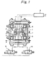
- a diaphragm pump according to the prior art has a structure shown in Figs. 1 through 4. As illustrated in Fig. 4, a diaphragm 4 defining a pump chamber 2 and a drive chamber 3 is provided on one end of a reciprocating rod 1, and a diaphragm 7 defining a pump chamber 5 and a drive chamber 6 is provided on the 1.
- the diaphragm pump has a controller 8 and changeover control valves 9 and 10.
- a driving fluid air, for example
- Fig. 2 shows the conditions which prevail during the driving of the reciprocating rod to the first side.
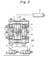
- this stopping position is sensed by a proximity sensor 11, as depicted in Fig. 3, in response to which the changeover control valves 9, 10 are changed over so that driving fluid is supplied to the drive chamber 6 on the second side of the reciprocating rod 1 to drive the reciprocating rod 1 to this side (the direction of arrow B) and expel the pump fluid from the pump chamber 5 on this side. Meanwhile, driving fluid in the drive chamber 3 on the first side of the reciprocating rod 1 is exhausted, during which time pump fluid is drawn into the pump chamber 2 on this side.
- this stopping position is sensed by a proximity sensor 12, as depicted in Fig.
- the diaphragm reversal phenomenon occurs, a situation arises in which stable, quantitatively accurate discharge of the pump fluid cannot be performed. If the diaphragm reversal phenomenon occurs frequently, moreover, the pump fluid undergoes agitation within the pump chamber. If the pump fluid contains fibers, the fibers will be destroyed by agitation resulting from the reversal phenomenon. If the pump fluid contains air bubbles, the air bubbles will be destroyed by agitation. Such destruction of fibers or air bubbles is undesirable. Furthermore, the service life of the diaphragms is shortened by the reversal phenomenon. This makes necessary the frequent replacement of the diaphragms and results in prolonged downtime. If the diaphragms tear because of shortened service life, outflow of the pump fluid can occur. This can result in a dangerous situation if the pump fluid is a toxic or hazardous substance.
- an object of the present invention is to provide a diaphragm pump wherein the reversal phenomenon, in which a diaphragm, which should expand toward the side of the pump chamber, contracts toward the drive chamber, or vice versa, is prevented from occurring both when the diaphragm pump is operating and when it is at rest, whereby the flexing of the diaphragm is regularized so that the diaphragm is made to reverse correctly during pump operation to make possible the reliable and accurate pumping of fluid.
- a diaphragm pump for discharging a pump fluid continuously by a diaphragm defining a pump chamber and a drive chamber, comprising pressure control means for controlling pressure of a driving fluid, which is supplied to the drive chamber neighboring the pump chamber via the intermediary of the diaphragm, in such a manner that pressure in the drive chamber becomes higher than pressure in the pump chamber when the pressure in the pump chamber is equal to or greater than the pressure in the drive chamber, whereby reversal of the diaphragm is prevented independently of the pressure in the pump chamber.
- the pressure control means includes a pressure sensor for sensing the pressure in the drive chamber, or a pressure sensor for sensing the pressure in the pump chamber, or pressure sensors for sensing the pressure in respective ones of the drive and pump chambers.
- the diaphragm pump further comprises a connecting body for guiding reciprocation of the diaphragm.
- the connecting body is a rod body, a plate body or a spring.
- the diaphragm pump is further characterized in that the pressure control means is actuated when the pump fluid is traveling through the pump chamber.
- the pressure control means is actuated when the pump fluid is not traveling through the pump chamber.
- a diaphragm pump which has a pair of diaphragms each of which defines a pump chamber and a drive chamber, for discharging a pump fluid continuously by reciprocation of the pair of diaphragms, comprising pressure control means for controlling pressure of a driving fluid, which is supplied to the drive chambers neighboring the pump chambers via the intermediary of the respective diaphragms, in such a manner that pressure in the drive chambers becomes higher than pressure in the pump chambers when the pressure in the pump chambers is equal to or greater than the pressure in the drive chambers, whereby reversal of each diaphragm is prevented.
- the pressure control means includes a pressure sensor for sensing the pressure in each drive chamber, or a pressure sensor for sensing the pressure in each pump chamber, or pressure sensors for sensing the pressure in each of the drive chambers and in each of the pump chambers.
- the diaphragm pump further comprises a connecting body for guiding reciprocation of the diaphragm.
- the connecting body is a rod body, a plate body or a spring.
- the diaphragm pump is further characterized in that the pressure control means is actuated when the pump fluid is traveling through the pump chamber.
- the pressure control means is actuated when the pump fluid is not traveling through the pump chamber.
- a diaphragm pump including a connecting body having two ends each of which is provided with a diaphragm defining a pump chamber and a drive chamber, and a control circuit for controlling reciprocation timing of the connecting body as well as timing at which supply of a driving fluid to each of the drive chambers is changed over, wherein when the connecting body is driven toward a first side thereof, the driving fluid is supplied to the drive chamber located on the first side of the connecting body, pump fluid is expelled from the pump chamber located on the first side and pump fluid is drawn into the pump chamber located on a second side of the connecting body while driving fluid is discharged from the drive chamber located on the second side, and when the connecting body is driven toward the second side thereof, the driving fluid is supplied to the drive chamber located on the second side of the connecting body, pump fluid is expelled from the pump chamber located on the second side and pump fluid is drawn into the pump chamber located on the first side of the connecting body while driving fluid is discharged from the drive chamber
- Passageways for supplying the driving fluid are connected to respective ones of the drive chambers and the pressure control means is provided in each passageway at a point along the length thereof.
- the present invention is applicable to a single-diaphragm pump incorporating a single diaphragm and to double-diaphragm pump incorporating two diaphragms.
- a connecting body is used to guide diaphragm reciprocation where necessary.
- the connecting body may be a telescoping or simply rod- shaped rod body, a small, disk-shaped plate or a spring such as a helical spring.
- the connecting body is for suitably supporting the diaphragms in the pump vessel or for interconnecting the diaphragms to assure the proper motion of the diaphragms in the double-diaphragm pump.
- Pressure sensing means is provided in the drive chamber or pump chamber or in both of these chambers. Alternatively, however, pressure sensing means is not provided, in which case diaphragm reversal can be prevented by holding the driving fluid at a positive pressure of, say, 0.5 kg/cm 2 with respect to the pressure of the pump fluid and producing a differential pressure between the pressure of the driving fluid to the pressure of the pump fluid by a pressure barrier, the differential pressure acting to prevent diaphragm reversal.
- the pressure of the pump fluid may rise owing to head pressure or the like even when the diaphragm pump is not operating. In such case diaphragm reversal is caused by the pressure difference between the pump and drive chambers. If a prescribed back pressure that takes head pressure into account is supplied to an air chamber on the side of the drive chamber, diaphragm reversal can be prevented.
- a reciprocating rod 21 serving as a connecting body is provided at the center of a diaphragm pump housing 20 so as to be movable in the horizontal direction.
- a ring-shaped magnetic plate 22 is attached to the reciprocating rod 21 at the exact center thereof.
- One end of the reciprocating rod 21 is provided with a diaphragm 23 and the other end with a diaphragm 24.
- the diaphragms 23, 24 are secured at their central portions to respective ends of the reciprocating rod 21 by mounting members 25, 26, respectively, and at their circumferential portions to the diaphragm pump housing 20 by mounting members 27.
- Spaces 28, 29 which allow the movement of the reciprocating rod 21 exist on respective sides of the reciprocating rod 21 in terms of the driving direction thereof.
- the space 28 is partitioned into a pump chamber 30 and a drive chamber 31 by the diaphragm 23, and the space 29 is partitioned into a pump chamber 32 and a drive chamber 33 by the diaphragm 24.
- the diaphragm 23 is in a state in which it is expanded toward the side of the pump chamber 30 and the diaphragm 24 s in a state in which it is expanded toward the side of the pump chamber 32.
- a supply passage 34 for supplying pump fluid to the pump chambers 30, 32 is provided in the lower part of the diaphragm pump housing 20.
- a discharge passage 35 for discharging the pump fluid within the pump chambers to the exterior of the pump.
- the lower portions of the pump chambers 30, 32 are provided with intake ports 36, 37, respectively, communicating with the supply passage 34.
- the upper portions of the pump chambers 30, 32 are provided with outlet ports 38, 39, respectively, communicating with the discharge passage 35.
- the intake ports 36, 37 and outlet ports 38, 39 are provided with ball valves 40, 41, 42, 43, respectively, serving as check valves for opening and closing the respective ports.
- the diaphragm pump housing 20 is formed to have passageways 44, 45 communicating with the drive chambers 31, 33, respectively.
- the passageway 44 is connected to a driving fluid supply pipe 48 via a passageway 46 and a changeover control valve 47
- the passageway 45 is connected to the driving fluid supply pipe 48 via a passageway 49 and a changeover control valve 50.
- the driving fluid supply pipe 48 functions to supply the drive chambers 31, 33 with air as the driving fluid.
- the changeover control valves 47, 50 have intake ports 51, 52; discharge ports 53, 54; and stop valves 55, 56; 57, 58, respectively.
- the changeover control valves 47, 50 are controlled by a controller 59.
- the main functions of the controller 59 are to sense the position to which the reciprocating rod 21 has been moved and alternately change over the changeover control valves 47, 50 to thereby control the operation timing of the reciprocating rod 21, and to regulate the pressure of the supplied air as the driving fluid based upon output signals from pressure sensors, described below.
- the diaphragm pump housing 20 is provided with magnet sensors 60, 61 as proximity sensors confronting the zone in which the magnetic plate 22 reciprocates. The outputs of the magnet sensors 60, 61 are fed into the controller 59.
- the pump chamber 30 is provided with a pressure sensor (a capacitor-type pressure-sensitive element or a piezoelectric element) 62 for sensing the pressure of the pump fluid in the pump chamber 30, the drive chamber 31 neighboring the pump chamber 30 is provided with a pressure sensor 63 for sensing the pressure of the driving fluid, the pump chamber 32 is provided with a pressure sensor 64, and the drive chamber 33 neighboring the pump chamber 32 is provided with a pressure sensor 65.
- the outputs of the pressure sensors 62 - 65 enter the controller 59.
- pressure regulators 66, 67 serving as pressure control means for regulating the pressure of the driving fluid which flows into the passageways 44, 45.
- the pressure regulators 66, 67 are controlled by the controller 59.
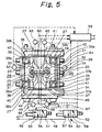
- the reciprocating rod 21 is located at a neutral position, as shown in Fig. 5, when the diaphragm pump is in the quiescent state.
- the ball valves 40, 41 under their own weight, have closed entrances 36a, 37a to the intake ports 36, 37 on the side of the supply passage 34; entrances 36b, 37b on the side of the pump chambers 30, 32 are open.
- the ball valves 42, 43 have closed exits 38a, 39a of the discharge ports 38, 39 on the side of the pump chambers 30, 32 and have opened exits 38b, 39b on the side of the discharge passage 35.
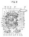
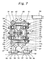
- the magnet sensor 60 senses the stopping position and the controller 59 responds by switching the changeover control valve 47 to the side of the discharge port 53 and switching the changeover control valve 50 to the side of the intake port 52, as depicted in Fig. 7.
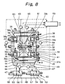
- Driving fluid is thus supplied to the drive chamber 33 and driving fluid is expelled into the atmosphere from the drive chamber 31 to drive the reciprocating rod 21 toward a second side (in the direction of arrow B), as shown in Fig. 8.
- the volume on the side of the pump chamber 32 decreases and the pressure of the pump fluid rises, thereby urging and displacing the ball valve 43 which is blocking the exit 39a of the discharge port 39 on the side of the fluid chamber 33.
- the discharge port 39 is thus opened.
- the ball valve 41 closes the entrance 37a to the discharge port 37. Accordingly, the pump fluid in the pump chamber 32 is discharged to the outside of the pump through the discharge passage 35.
- the controller 59 controls the pressure regulator 66 on the basis of the output signals from the two pressure sensors 62, 63 so as to elevate the pressure of the driving fluid in the drive chamber 31.
- the controller 59 controls the pressure regulator 67 on the basis of the output signals from the two pressure sensors 64, 65 so as to elevate the pressure of the driving fluid in the drive chamber 33.
- the pressure of the driving fluid in the driving chamber is maintained at a level higher than the pressure of the pump fluid in the pump chamber. This makes it possible to prevent the so-called reversal phenomenon, wherein a diaphragm that should expand toward the pump chamber contracts toward the drive chamber instead during driving of the diaphragm.
Landscapes
- Engineering & Computer Science (AREA)
- Mechanical Engineering (AREA)
- General Engineering & Computer Science (AREA)
- Reciprocating Pumps (AREA)
- Check Valves (AREA)
Description
- This invention relates to improvements in a diaphragm pump of the type which discharges a pump fluid continuously by a diaphragm defining a pump chamber and a drive chamber.
- A diaphragm pump according to the prior art has a structure shown in Figs. 1 through 4. As illustrated in Fig. 4, a
diaphragm 4 defining apump chamber 2 and adrive chamber 3 is provided on one end of a reciprocatingrod 1, and adiaphragm 7 defining apump chamber 5 and adrive chamber 6 is provided on the 1. The diaphragm pump has acontroller 8 andchangeover control valves reciprocating rod 1 is driven to one (a first) side (in the direction of arrow A), as illustrated in Fig. 1, a driving fluid (air, for example) is supplied to thedrive chamber 3 on the first side of thereciprocating rod 1 to expel the pump fluid from thepump chamber 2 on this side. Meanwhile, driving fluid (air) in thedrive chamber 6 on the other (a second) side of the reciprocatingrod 1 is exhausted, during which time pump fluid is drawn into thepump chamber 5 on this side. Fig. 2 shows the conditions which prevail during the driving of the reciprocating rod to the first side. - When the
control rod 1 reaches its stopping position on the first side, this stopping position is sensed by aproximity sensor 11, as depicted in Fig. 3, in response to which thechangeover control valves drive chamber 6 on the second side of thereciprocating rod 1 to drive thereciprocating rod 1 to this side (the direction of arrow B) and expel the pump fluid from thepump chamber 5 on this side. Meanwhile, driving fluid in thedrive chamber 3 on the first side of thereciprocating rod 1 is exhausted, during which time pump fluid is drawn into thepump chamber 2 on this side. When the reciprocatingrod 1 reaches its stopping position on the second side, this stopping position is sensed by aproximity sensor 12, as depicted in Fig. 4, in response to which thechangeover control valves rod 1 is reciprocated repeatedly to discharge the pump fluid continuously by this reciprocating motion. Such a diaphragm type pump is disclosed in US-A-5 281 107. - During the reciprocation of the reciprocating
rod 1, there are occasions where the pressure of the pump fluid expelled from one of the pump chambers exceeds the pressure of the driving fluid in the neighboring drive chamber for some reason. For example, if the pressure of the pump chamber surpasses the pressure in thedrive chamber 3 for some reason during the movement of thereciprocating rod 1 to the first side (i.e., during the discharge of the pump fluid), there is the danger that thediaphragm 4, which should expand toward the side of thepump chamber 2, will contract toward thedrive chamber 3, as indicated by thedashed line 4' in Fig. 2. This is referred to as a diaphragm reversal phenomenon. This phenomenon occurs also in a case where the pressure in thepump chamber 2 surpasses the pressure in thedrive chamber 3 during movement of thereciprocating rod 1 to the second side (i.e., during the intake of the pump fluid into the pump chamber 2). (See thedashed line 4' in Fig. 3.) - When the diaphragm reversal phenomenon occurs, a situation arises in which stable, quantitatively accurate discharge of the pump fluid cannot be performed. If the diaphragm reversal phenomenon occurs frequently, moreover, the pump fluid undergoes agitation within the pump chamber. If the pump fluid contains fibers, the fibers will be destroyed by agitation resulting from the reversal phenomenon. If the pump fluid contains air bubbles, the air bubbles will be destroyed by agitation. Such destruction of fibers or air bubbles is undesirable. Furthermore, the service life of the diaphragms is shortened by the reversal phenomenon. This makes necessary the frequent replacement of the diaphragms and results in prolonged downtime. If the diaphragms tear because of shortened service life, outflow of the pump fluid can occur. This can result in a dangerous situation if the pump fluid is a toxic or hazardous substance.
- Accordingly, an object of the present invention is to provide a diaphragm pump wherein the reversal phenomenon, in which a diaphragm, which should expand toward the side of the pump chamber, contracts toward the drive chamber, or vice versa, is prevented from occurring both when the diaphragm pump is operating and when it is at rest, whereby the flexing of the diaphragm is regularized so that the diaphragm is made to reverse correctly during pump operation to make possible the reliable and accurate pumping of fluid.
- According to the present invention, the foregoing object is attained by providing a diaphragm pump for discharging a pump fluid continuously by a diaphragm defining a pump chamber and a drive chamber, comprising pressure control means for controlling pressure of a driving fluid, which is supplied to the drive chamber neighboring the pump chamber via the intermediary of the diaphragm, in such a manner that pressure in the drive chamber becomes higher than pressure in the pump chamber when the pressure in the pump chamber is equal to or greater than the pressure in the drive chamber, whereby reversal of the diaphragm is prevented independently of the pressure in the pump chamber.
- In an embodiment of the present invention, the pressure control means includes a pressure sensor for sensing the pressure in the drive chamber, or a pressure sensor for sensing the pressure in the pump chamber, or pressure sensors for sensing the pressure in respective ones of the drive and pump chambers.
- In the embodiment of the present invention, the diaphragm pump further comprises a connecting body for guiding reciprocation of the diaphragm.
- The connecting body is a rod body, a plate body or a spring.
- The diaphragm pump is further characterized in that the pressure control means is actuated when the pump fluid is traveling through the pump chamber.
- Alternatively, the pressure control means is actuated when the pump fluid is not traveling through the pump chamber.
- In another aspect of the present invention, the foregoing object is attained by providing a diaphragm pump, which has a pair of diaphragms each of which defines a pump chamber and a drive chamber, for discharging a pump fluid continuously by reciprocation of the pair of diaphragms, comprising pressure control means for controlling pressure of a driving fluid, which is supplied to the drive chambers neighboring the pump chambers via the intermediary of the respective diaphragms, in such a manner that pressure in the drive chambers becomes higher than pressure in the pump chambers when the pressure in the pump chambers is equal to or greater than the pressure in the drive chambers, whereby reversal of each diaphragm is prevented.
- In an embodiment of the present invention, the pressure control means includes a pressure sensor for sensing the pressure in each drive chamber, or a pressure sensor for sensing the pressure in each pump chamber, or pressure sensors for sensing the pressure in each of the drive chambers and in each of the pump chambers.
- In the embodiment of the present invention, the diaphragm pump further comprises a connecting body for guiding reciprocation of the diaphragm.
- The connecting body is a rod body, a plate body or a spring.
- The diaphragm pump is further characterized in that the pressure control means is actuated when the pump fluid is traveling through the pump chamber.
- Alternatively, the pressure control means is actuated when the pump fluid is not traveling through the pump chamber.
- In a further aspect of the present invention, the foregoing object is attained by providing a diaphragm pump including a connecting body having two ends each of which is provided with a diaphragm defining a pump chamber and a drive chamber, and a control circuit for controlling reciprocation timing of the connecting body as well as timing at which supply of a driving fluid to each of the drive chambers is changed over, wherein when the connecting body is driven toward a first side thereof, the driving fluid is supplied to the drive chamber located on the first side of the connecting body, pump fluid is expelled from the pump chamber located on the first side and pump fluid is drawn into the pump chamber located on a second side of the connecting body while driving fluid is discharged from the drive chamber located on the second side, and when the connecting body is driven toward the second side thereof, the driving fluid is supplied to the drive chamber located on the second side of the connecting body, pump fluid is expelled from the pump chamber located on the second side and pump fluid is drawn into the pump chamber located on the first side of the connecting body while driving fluid is discharged from the drive chamber located on the second side, whereby the pump fluid is discharged continuously by reciprocation of the connecting body, the diaphragm pump comprising a pressure sensor provided in each pump chamber for sensing pressure of the pump fluid in each pump chamber, a pressure sensor provided in each drive chamber for sensing pressure of the driving fluid in each drive chamber, and pressure control means for controlling the pressure of the driving fluid based upon output signals from both of the pressure sensors in such a manner that the pressure of the driving fluid in each drive chamber neighboring each pump chamber becomes higher than the pressure of the pump fluid in the pump chamber when the pressure of the pump fluid in the pump chambers is equal to or greater than the pressure of the driving fluid in the drive chambers neighboring the pump chambers via the intermediary of the respective diaphragms.
- Passageways for supplying the driving fluid are connected to respective ones of the drive chambers and the pressure control means is provided in each passageway at a point along the length thereof.
- Thus, the present invention is applicable to a single-diaphragm pump incorporating a single diaphragm and to double-diaphragm pump incorporating two diaphragms. A connecting body is used to guide diaphragm reciprocation where necessary. The connecting body may be a telescoping or simply rod- shaped rod body, a small, disk-shaped plate or a spring such as a helical spring. The connecting body is for suitably supporting the diaphragms in the pump vessel or for interconnecting the diaphragms to assure the proper motion of the diaphragms in the double-diaphragm pump.
- Pressure sensing means is provided in the drive chamber or pump chamber or in both of these chambers. Alternatively, however, pressure sensing means is not provided, in which case diaphragm reversal can be prevented by holding the driving fluid at a positive pressure of, say, 0.5 kg/cm2 with respect to the pressure of the pump fluid and producing a differential pressure between the pressure of the driving fluid to the pressure of the pump fluid by a pressure barrier, the differential pressure acting to prevent diaphragm reversal.
- The pressure of the pump fluid may rise owing to head pressure or the like even when the diaphragm pump is not operating. In such case diaphragm reversal is caused by the pressure difference between the pump and drive chambers. If a prescribed back pressure that takes head pressure into account is supplied to an air chamber on the side of the drive chamber, diaphragm reversal can be prevented.
- Other features and advantages of the present invention will be apparent from the following description taken in conjunction with the accompanying drawings, in which like reference characters designate the same or similar parts throughout the figures thereof.
- Fig. 1 is a sectional view illustrating a diaphragm pump according to the prior art, the pump being shown in a state which prevails immediately after a reciprocating rod has been moved from a second side to a first side;
- Fig. 2 is a sectional view illustrating the diaphragm pump according to the prior art, the pump being shown in a state which prevails while the reciprocating rod is being moved from the second side to the first side;
- Fig. 3 is a sectional view illustrating the diaphragm pump according to the prior art, the pump being shown in a state which prevails immediately after the reciprocating rod has reached a stopping position on the first side and a changeover control valve has been changed over;
- Fig. 4 is a sectional view illustrating the diaphragm pump according to the prior art, the pump being shown in a state which prevails immediately before the reciprocating rod reaches a stopping position on the second side;
- Fig. 5 is a sectional view illustrating a diaphragm pump according to the present invention, the pump being shown in a state in which a reciprocating rod is at a neutral position when the pump is at rest;
- Fig. 6 is a sectional view illustrating the diaphragm pump according to the present invention, the pump being shown in a state in which the reciprocating rod has reached a stopping position on a first side;
- Fig. 7 is a sectional view illustrating the diaphragm pump according to the present invention, the pump being shown in a state which prevails immediately after the reciprocating rod has reached the stopping position on the first side and a changeover control valve has been changed over; and
- Fig. 8 is a sectional view illustrating the diaphragm pump according to the present invention, the pump being shown in a state which prevails immediately before the reciprocating rod reaches a stopping position on a second side.
-
- A preferred embodiment of a diaphragm pump according to the present invention will now be described with reference to Figs. 5 through 8.
- As shown in Fig. 5, a reciprocating
rod 21 serving as a connecting body is provided at the center of adiaphragm pump housing 20 so as to be movable in the horizontal direction. A ring-shapedmagnetic plate 22 is attached to the reciprocatingrod 21 at the exact center thereof. One end of the reciprocatingrod 21 is provided with adiaphragm 23 and the other end with adiaphragm 24. Thediaphragms rod 21 by mountingmembers diaphragm pump housing 20 by mountingmembers 27.Spaces rod 21 exist on respective sides of the reciprocatingrod 21 in terms of the driving direction thereof. Thespace 28 is partitioned into apump chamber 30 and adrive chamber 31 by thediaphragm 23, and thespace 29 is partitioned into apump chamber 32 and adrive chamber 33 by thediaphragm 24. Under ordinary conditions, i.e., in the absence of fluid, thediaphragm 23 is in a state in which it is expanded toward the side of thepump chamber 30 and the diaphragm 24 s in a state in which it is expanded toward the side of thepump chamber 32. - A
supply passage 34 for supplying pump fluid to thepump chambers diaphragm pump housing 20. Provided in the upper part of thediaphragm pump housing 20 is adischarge passage 35 for discharging the pump fluid within the pump chambers to the exterior of the pump. The lower portions of thepump chambers intake ports supply passage 34. The upper portions of thepump chambers outlet ports discharge passage 35. Theintake ports outlet ports ball valves - The
diaphragm pump housing 20 is formed to havepassageways drive chambers passageway 44 is connected to a drivingfluid supply pipe 48 via apassageway 46 and achangeover control valve 47, and thepassageway 45 is connected to the drivingfluid supply pipe 48 via apassageway 49 and achangeover control valve 50. The drivingfluid supply pipe 48 functions to supply thedrive chambers changeover control valves intake ports discharge ports valves changeover control valves controller 59. - The main functions of the
controller 59 are to sense the position to which thereciprocating rod 21 has been moved and alternately change over thechangeover control valves rod 21, and to regulate the pressure of the supplied air as the driving fluid based upon output signals from pressure sensors, described below. Thediaphragm pump housing 20 is provided withmagnet sensors magnetic plate 22 reciprocates. The outputs of themagnet sensors controller 59. - The
pump chamber 30 is provided with a pressure sensor (a capacitor-type pressure-sensitive element or a piezoelectric element) 62 for sensing the pressure of the pump fluid in thepump chamber 30, thedrive chamber 31 neighboring thepump chamber 30 is provided with apressure sensor 63 for sensing the pressure of the driving fluid, thepump chamber 32 is provided with apressure sensor 64, and thedrive chamber 33 neighboring thepump chamber 32 is provided with apressure sensor 65. The outputs of the pressure sensors 62 - 65 enter thecontroller 59. - Provided in the
passageways pressure regulators passageways controller 59. - The reciprocating
rod 21 is located at a neutral position, as shown in Fig. 5, when the diaphragm pump is in the quiescent state. Here theball valves entrances intake ports supply passage 34;entrances pump chambers ball valves exits discharge ports pump chambers exits discharge passage 35. - Power-supply voltage is applied to the
controller 59, whereby thechangeover control valve 47 is switched to the side of theintake port 51 and thechangeover control valve 50 is switched to the side of thedischarge port 54. When this is done the driving fluid is supplied to thedrive chamber 31 and the driving fluid is expelled into the atmosphere from thedrive chamber 33, whereby the reciprocatingrod 21 is driven toward a first side (in the direction of arrow A), as illustrated in Fig. 6. As a result, the volume on the side of thepump chamber 30 decreases and the pressure of the pump fluid rises, thereby urging and displacing theball valve 42 which is blocking theexit 38a of thedischarge port 38 on the side of thefluid chamber 30. Thedischarge port 38 is thus opened. It should be noted that theball valve 40 continues to keep theentrance 36a to theintake port 36 closed. Accordingly, the pump fluid in thepump chamber 30 is discharged to the outside of the pump through thedischarge passage 35. - Meanwhile, the volume of the
drive chamber 33 decreases and the volume of thepump chamber 32 increases. Consequently, the pressure in thepump chamber 32 declines and theentrance 37a to theintake port 37 is opened. Theball valve 43 continues to keep theexit 39a to thedischarge port 39 closed. Accordingly, pump fluid is supplied to thepump chamber 32 through thesupply passage 34. - When the reciprocating
rod 21 reaches its stopping position on the first side, as shown in Fig. 6, themagnet sensor 60 senses the stopping position and thecontroller 59 responds by switching thechangeover control valve 47 to the side of thedischarge port 53 and switching thechangeover control valve 50 to the side of theintake port 52, as depicted in Fig. 7. Driving fluid is thus supplied to thedrive chamber 33 and driving fluid is expelled into the atmosphere from thedrive chamber 31 to drive the reciprocatingrod 21 toward a second side (in the direction of arrow B), as shown in Fig. 8. As a result, the volume on the side of thepump chamber 32 decreases and the pressure of the pump fluid rises, thereby urging and displacing theball valve 43 which is blocking theexit 39a of thedischarge port 39 on the side of thefluid chamber 33. Thedischarge port 39 is thus opened. It should be noted that theball valve 41 closes theentrance 37a to thedischarge port 37. Accordingly, the pump fluid in thepump chamber 32 is discharged to the outside of the pump through thedischarge passage 35. - Meanwhile, the volume of the
drive chamber 31 decreases and the volume of thepump chamber 30 increases. Consequently, the pressure in thepump chamber 30 declines and theentrance 36a to theintake port 36 is opened. Accordingly, pump fluid is supplied to thepump chamber 30 through thesupply passage 34. - Assume that the pressure in the
pump chamber 30 has surpassed the pressure in thedrive chamber 31 for some reason during the reciprocation of the reciprocatingrod 21. In such case thecontroller 59 controls thepressure regulator 66 on the basis of the output signals from the twopressure sensors drive chamber 31. Next, assume that the pressure in thepump chamber 32 has surpassed the pressure in thedrive chamber 33 for some reason during the reciprocation of the reciprocatingrod 21. In such case thecontroller 59 controls thepressure regulator 67 on the basis of the output signals from the twopressure sensors drive chamber 33. - Thus, in accordance with the present invention, the pressure of the driving fluid in the driving chamber is maintained at a level higher than the pressure of the pump fluid in the pump chamber. This makes it possible to prevent the so-called reversal phenomenon, wherein a diaphragm that should expand toward the pump chamber contracts toward the drive chamber instead during driving of the diaphragm.
- Preventing the reversal phenomenon makes it possible to assure reliable, accurate pump operation at all times.
Claims (14)
- A diaphragm pump for discharging a pump fluid continuously by a diaphragm defining a pump chamber (30,32) and a drive chamber (31, 33), characterised in that:a pressure control means (59, 62-67) is provided including a pressure sensor (62, 64) for sensing the pressure in said pump chamber (30, 32), the pressure control means (59, 62-67) controlling pressure of a driving fluid, which is supplied to said drive chamber (31, 33) neighboring said pump chamber (30, 32) via the intermediary of said diaphragm (23, 24), in such a manner that pressure in said drive chamber (31, 33) becomes higher than pressure in said pump chamber (30, 32) when the pressure in said pump chamber (30, 32) is equal or greater than the pressure in said drive chamber (31, 33), whereby reversal of said diaphragm (23, 24) is prevented independently of the pressure in said pump chamber (30, 32).
- The diaphragm pump according to claim 1, wherein said pressure control means (59, 62-67) includes a pressure sensor (63, 65) for sensing the pressure in said drive chamber (31, 33).
- The diaphragm pump according to claim 1 or 2, wherein said diaphragm pump further comprises a connecting body (21) for guiding reciprocation of said diaphragm (23, 24).
- The diaphragm pump according to claim 3, wherein said connecting body is a rod (21), a plate or a spring.
- The diaphragm pump according to any one of claims 1-4, wherein said pressure control means (59, 62-67) is actuated when the pump fluid is traveling through said pump chamber (30, 32).
- The diaphragm pump according to any one of claims 1-4, wherein said pressure control means (59, 62-67) is actuated when the pump fluid is not traveling through said pump chamber (30, 32).
- A diaphragm pump according to claim 1, which has a pair of diaphragms (23, 24) each of which defines a pump chamber (30, 32) and a drive chamber (31, 33), for discharging a pump fluid continuously by reciprocation of the pair of diaphragms (23, 24), comprising: pressure control means (59, 62-67) including pressure sensors (62, 64) for sensing the pressure in respective pump chambers (30, 32), the pressure control means (59, 62-67) controlling pressure of a driving fluid, which is supplied to said drive chambers (31, 33) neighboring said pump chambers (30, 32) via the intermediary of the respective diaphragms (23, 24), in such a manner that pressure in said drive chambers (31, 33) becomes higher than pressure in said pump chambers (30, 32) when the pressure in said pump chambers (30, 32) is equal to or greater than the pressure in said drive chambers (31, 33), whereby reversal of each diaphragm (23, 24) is prevented.
- The diaphragm pump according to claim 7, wherein said pressure control means includes pressure sensors (63, 65) for sensing the pressure in respective drive chambers (31, 33).
- The diaphragm pump according to claim 7 or 8, wherein said diaphragm pump further comprises a connecting body (21) for guiding reciprocation of said diaphragm (23,24).
- The diaphragm pump according to claim 9, wherein said connecting body is a rod (21), a plate or a spring.
- The diaphragm pump according to any one of claims 7-10, wherein said pressure control means (59, 62-67) is actuated when the pump fluid is traveling through said pump chamber (30, 32).
- The diaphragm pump according to any one of claims 7-10, wherein said pressure control means (59, 62-67) is actuated when the pump fluid is not traveling through said pump chamber (30, 32).
- A diaphragm pump according to claim 1, including a connecting body (21) having two ends each of which is provided with a diaphragm (23, 24) defining a pump chamber (30, 32) and a drive chamber (31, 33), and a control circuit (59) for controlling reciprocation timing of said connecting body (21) as well as timing at which supply of a driving fluid to each of said drive chambers (31, 33) is changed over, wherein when said connecting body (21) is driven toward a first side thereof, the driving fluid is supplied to the drive chamber (31) located on the first side of said connecting body (21), pump fluid is expelled from the pump chamber (30) located on the first side and pump fluid is drawn into the pump chamber (32) located on a second side of said connecting body (21) while driving fluid is discharged from the drive chamber (33) located on the second side, and when said connecting body (21) is driven toward the second side thereof, the driving fluid is supplied to said drive chamber (33) located on the second side of said connecting body (21), pump fluid is expelled from said pump chamber (32) located on the second side and pump fluid is drawn into said pump chamber (30) located on the first side of said connecting body (21) while driving fluid is discharged from said drive chamber (33) located on the second side, whereby the pump fluid is discharged continuously by reciprocation of said connecting body (21), the diaphragm pump comprising:a pressure sensor (62, 64) provided in each pump chamber (30, 32) for sensing pressure of the pump fluid in each pump chamber (30, 32);a pressure sensor (63, 65) provided in each drive chamber (31, 33) for sensing pressure of the driving fluid in each drive chamber (31, 33); andpressure control means (59, 62-67) for controlling the pressure of the driving fluid based upon output signals from both of said pressure sensors in such a manner that the pressure of the driving fluid in each drive chamber (31, 33) neighboring each pump chamber (30, 32) becomes higher than the pressure of the pump fluid in the pump chamber (30, 32) when the pressure of the pump fluid in the pump chambers (30, 32) is equal to or greater than the pressure of the driving fluid in the drive chambers (31, 33) neighboring the pump chambers (30,32) via the intermediary of the respective diaphragms (23, 24).
- The diaphragm pump according to claim 13, wherein passageways for supplying the driving fluid are connected to respective ones of said drive chambers (31, 33) and said pressure control means is provided in each passageway at a point along the length thereof.
Applications Claiming Priority (3)
| Application Number | Priority Date | Filing Date | Title |
|---|---|---|---|
| JP253329/97 | 1997-09-18 | ||
| JP25332997 | 1997-09-18 | ||
| JP09253329A JP3083275B2 (en) | 1997-09-18 | 1997-09-18 | Double diaphragm pump |
Publications (3)
| Publication Number | Publication Date |
|---|---|
| EP0903496A2 EP0903496A2 (en) | 1999-03-24 |
| EP0903496A3 EP0903496A3 (en) | 1999-10-20 |
| EP0903496B1 true EP0903496B1 (en) | 2004-09-29 |
Family
ID=17249803
Family Applications (1)
| Application Number | Title | Priority Date | Filing Date |
|---|---|---|---|
| EP97121474A Expired - Lifetime EP0903496B1 (en) | 1997-09-18 | 1997-12-05 | Pressure control for a double diaphragm pump |
Country Status (7)
| Country | Link |
|---|---|
| US (1) | US6126403A (en) |
| EP (1) | EP0903496B1 (en) |
| JP (1) | JP3083275B2 (en) |
| KR (1) | KR100330428B1 (en) |
| CN (1) | CN1136393C (en) |
| DE (1) | DE69730958T2 (en) |
| TW (1) | TW362140B (en) |
Families Citing this family (65)
| Publication number | Priority date | Publication date | Assignee | Title |
|---|---|---|---|---|
| US6497676B1 (en) | 2000-02-10 | 2002-12-24 | Baxter International | Method and apparatus for monitoring and controlling peritoneal dialysis therapy |
| DE10012904B4 (en) * | 2000-03-16 | 2004-08-12 | Lewa Herbert Ott Gmbh + Co | Membrane clamping with elasticity compensation |
| US6752599B2 (en) * | 2000-06-09 | 2004-06-22 | Alink M, Inc. | Apparatus for photoresist delivery |
| JP3515070B2 (en) | 2000-12-18 | 2004-04-05 | 株式会社ヤマダコーポレーション | Pump restarter |
| US20030017056A1 (en) * | 2001-07-19 | 2003-01-23 | Baxter International Inc. | Pump having flexible liner and merchandiser having such a pump |
| US6769231B2 (en) | 2001-07-19 | 2004-08-03 | Baxter International, Inc. | Apparatus, method and flexible bag for use in manufacturing |
| US6905314B2 (en) | 2001-10-16 | 2005-06-14 | Baxter International Inc. | Pump having flexible liner and compounding apparatus having such a pump |
| TW517141B (en) * | 2001-12-28 | 2003-01-11 | Nanya Technology Corp | Liquid supplying device |
| US7175606B2 (en) | 2002-05-24 | 2007-02-13 | Baxter International Inc. | Disposable medical fluid unit having rigid frame |
| US6939111B2 (en) | 2002-05-24 | 2005-09-06 | Baxter International Inc. | Method and apparatus for controlling medical fluid pressure |
| US7153286B2 (en) | 2002-05-24 | 2006-12-26 | Baxter International Inc. | Automated dialysis system |
| AU2003274901A1 (en) | 2002-07-19 | 2004-02-09 | Baxter Healthcare S.A. | Systems and methods for performing peritoneal dialysis |
| US7238164B2 (en) | 2002-07-19 | 2007-07-03 | Baxter International Inc. | Systems, methods and apparatuses for pumping cassette-based therapies |
| US6675593B1 (en) * | 2002-10-15 | 2004-01-13 | Michael Suydam | Water distribution apparatus |
| JP2004141744A (en) | 2002-10-23 | 2004-05-20 | Toppan Printing Co Ltd | Coating liquid supply apparatus and method |
| US7007824B2 (en) | 2003-01-24 | 2006-03-07 | Baxter International Inc. | Liquid dispenser and flexible bag therefor |
| JP4506122B2 (en) * | 2003-08-01 | 2010-07-21 | 凸版印刷株式会社 | Coating liquid supply device |
| JP4691503B2 (en) | 2003-10-28 | 2011-06-01 | バクスター・インターナショナル・インコーポレイテッド | Method and apparatus for improved priming, integrity and head height for medical fluid systems |
| US8029454B2 (en) | 2003-11-05 | 2011-10-04 | Baxter International Inc. | High convection home hemodialysis/hemofiltration and sorbent system |
| MX2007005973A (en) * | 2004-11-17 | 2007-11-12 | Proportionair Inc | Control system for an air operated diaphragm pump. |
| US7517199B2 (en) * | 2004-11-17 | 2009-04-14 | Proportion Air Incorporated | Control system for an air operated diaphragm pump |
| US7658598B2 (en) * | 2005-10-24 | 2010-02-09 | Proportionair, Incorporated | Method and control system for a pump |
| US20060219642A1 (en) * | 2005-04-04 | 2006-10-05 | Ingersoll-Rand Company | Control system and method for an air-operated pump |
| US7424847B2 (en) * | 2005-05-25 | 2008-09-16 | Hart Arthur S | Diaphragm assembly for a pump |
| US8197231B2 (en) | 2005-07-13 | 2012-06-12 | Purity Solutions Llc | Diaphragm pump and related methods |
| UA89254C2 (en) * | 2005-07-28 | 2010-01-11 | Грако Міннесота Інк. | Piston pump with electronic control of air valve and pump |
| US9677549B2 (en) | 2005-07-28 | 2017-06-13 | Graco Minnesota Inc. | Reciprocating pump with electronically monitored air valve and piston |
| US8568112B2 (en) | 2005-07-29 | 2013-10-29 | Graco Minnesota Inc. | Reciprocating piston pump with air valve, detent and poppets |
| ES2363717T3 (en) | 2005-07-29 | 2011-08-12 | Graco Minnesota Inc. | ALTERNATIVE PUMP WITH ELECTRONICALLY MONITORED AIR VALVE THAT HAS A BATTERY AND ELECTRONIC MONITORING BY SOLENOID. |
| JP4668027B2 (en) * | 2005-10-17 | 2011-04-13 | シーケーディ株式会社 | Chemical supply system |
| US20080003120A1 (en) * | 2006-06-30 | 2008-01-03 | Meza Humberto V | Pump apparatus and method |
| US7587897B2 (en) * | 2007-04-10 | 2009-09-15 | Illinois Tool Works Inc. | Magnetically sequenced pneumatic motor |
| US7603855B2 (en) * | 2007-04-10 | 2009-10-20 | Illinois Tool Works Inc. | Valve with magnetic detents |
| US7603854B2 (en) * | 2007-04-10 | 2009-10-20 | Illinois Tool Works Inc. | Pneumatically self-regulating valve |
| GB0707220D0 (en) * | 2007-04-14 | 2007-05-23 | Stratabolt Pty Ltd | Improved pump |
| US7681456B2 (en) * | 2008-06-20 | 2010-03-23 | Rosemount Inc. | Field device including a capillary tube having a non-cylindrical lumen |
| US8062513B2 (en) | 2008-07-09 | 2011-11-22 | Baxter International Inc. | Dialysis system and machine having therapy prescription recall |
| US9514283B2 (en) | 2008-07-09 | 2016-12-06 | Baxter International Inc. | Dialysis system having inventory management including online dextrose mixing |
| CN102143775B (en) * | 2008-10-22 | 2017-03-08 | 生物技术公司 | MEMS fluid valve with integrated pressure sensor for malfunction detection |
| WO2010069320A2 (en) * | 2008-12-19 | 2010-06-24 | Stobbe Tech A/S | Biopharmaceutical plant in a column |
| WO2010085744A2 (en) | 2009-01-23 | 2010-07-29 | Idex Aodd, Inc. | Method for increasing compressed air efficiency in a pump |
| CN102439308B (en) * | 2009-05-08 | 2014-10-22 | 沃伦鲁普公司 | Air operated diaphragm pump with generator |
| US8382445B2 (en) * | 2009-12-16 | 2013-02-26 | Warren Rupp, Inc. | Air logic controller |
| GB2478784B (en) * | 2010-03-19 | 2017-01-25 | Finishing Brands Holdings Inc | Improvements in diaphragm pumps |
| WO2013036240A1 (en) | 2011-09-09 | 2013-03-14 | Ingersoll Rand Company | Air motor having a programmable logic controller interface and a method of retrofitting an air motor |
| US9610392B2 (en) | 2012-06-08 | 2017-04-04 | Fresenius Medical Care Holdings, Inc. | Medical fluid cassettes and related systems and methods |
| US10054115B2 (en) | 2013-02-11 | 2018-08-21 | Ingersoll-Rand Company | Diaphragm pump with automatic priming function |
| US10036378B2 (en) | 2013-02-28 | 2018-07-31 | Ingersoll-Rand Company | Positive displacement pump with pressure compensating calibration |
| NZ630340A (en) * | 2013-05-14 | 2016-04-29 | Joe Santa & Ass Pty Ltd | A valve for a diaphragm pump |
| DE102013108948B4 (en) * | 2013-08-19 | 2018-02-01 | Uwe Nakoinz | Device for conveying liquids with the aid of a piezo drive device |
| GB2518411B (en) * | 2013-09-20 | 2020-04-29 | Alveier Ltd | Pump Control |
| US9605664B2 (en) * | 2014-01-07 | 2017-03-28 | Ingersoll-Rand Company | Pneumatic piston pump metering and dispense control |
| CN103967734A (en) * | 2014-05-26 | 2014-08-06 | 成都科佑达技术开发有限公司 | Pneumatic metering pump |
| CN105443362B (en) * | 2014-07-25 | 2018-04-06 | 上海绩优机电股份有限公司 | A kind of pneumatic diaphragm pump |
| CN104806514B (en) * | 2015-05-27 | 2017-01-04 | 陆秀尧 | Air-flow runs through type controlling valve |
| DE102015108963B4 (en) * | 2015-06-08 | 2019-11-14 | Timmer Gmbh | Pneumatically operated diaphragm pump, in particular double diaphragm pump |
| KR20230156168A (en) * | 2015-08-08 | 2023-11-13 | 스토베 게엠베하 | Disposable bioprocess system supporting biological activity |
| GB201519145D0 (en) * | 2015-10-29 | 2015-12-16 | Gas Measurement Instr Ltd | Smart pump for a portable gas detection instrument |
| US11179516B2 (en) | 2017-06-22 | 2021-11-23 | Baxter International Inc. | Systems and methods for incorporating patient pressure into medical fluid delivery |
| CN107725299A (en) * | 2017-09-29 | 2018-02-23 | 上海华虹宏力半导体制造有限公司 | Piston type stabilized pressure pump |
| JP6784721B2 (en) * | 2018-06-18 | 2020-11-11 | 株式会社ヤマダコーポレーション | Ball check valve and diaphragm pump |
| CN108916009A (en) * | 2018-06-25 | 2018-11-30 | 安徽乐昌气动流体设备科技有限公司 | A kind of pneumatic diaphragm pump of automatic control |
| EP3660335A1 (en) * | 2018-11-27 | 2020-06-03 | Berlin Heart GmbH | Switch unit and pneumatic system |
| KR102297725B1 (en) | 2021-04-30 | 2021-09-02 | 박병호 | Locking ring structure of diaphram pump |
| US12322781B2 (en) | 2022-01-06 | 2025-06-03 | Lg Energy Solution, Ltd. | Slurry transfer device and slurry transfer method using the same |
Family Cites Families (11)
| Publication number | Priority date | Publication date | Assignee | Title |
|---|---|---|---|---|
| DE2102762C3 (en) * | 1971-01-21 | 1978-09-14 | Tuchenhagen, Otto, 2059 Buechen | Device for regulating the pressure and delivery rate of a hydraulically operated diaphragm pump |
| US3814548A (en) * | 1971-08-05 | 1974-06-04 | Rupp Co Warren | Diaphragm pump apparatus |
| US4093403A (en) * | 1976-09-15 | 1978-06-06 | Outboard Marine Corporation | Multistage fluid-actuated diaphragm pump with amplified suction capability |
| GB2062774A (en) * | 1979-11-02 | 1981-05-28 | Bran & Luebbe Gb Ltd | Diaphragm Pump Control |
| US4856969A (en) * | 1987-04-01 | 1989-08-15 | The Gorman-Rupp Company | Fluid powered diaphragm pump with cycle timer |
| DE3737350A1 (en) * | 1987-11-04 | 1989-05-24 | Kopperschmidt Mueller & Co | PUMP ARRANGEMENT WITH DOUBLE PUMP |
| NL9101556A (en) * | 1991-09-16 | 1993-04-16 | Holthuis Bv | CONTROL SYSTEM FOR PISTON MEMBRANE PUMP. |
| US5332372A (en) * | 1992-04-20 | 1994-07-26 | Warren Rupp, Inc. | Modular double-diaphragm pump |
| US5252041A (en) * | 1992-04-30 | 1993-10-12 | Dorr-Oliver Incorporated | Automatic control system for diaphragm pumps |
| US5378122A (en) * | 1993-02-16 | 1995-01-03 | Wilden Pump & Engineering Co. | Air driven diaphragm pump |
| US5927954A (en) * | 1996-05-17 | 1999-07-27 | Wilden Pump & Engineering Co. | Amplified pressure air driven diaphragm pump and pressure relief value therefor |
-
1997
- 1997-09-18 JP JP09253329A patent/JP3083275B2/en not_active Expired - Lifetime
- 1997-12-04 TW TW086118248A patent/TW362140B/en active
- 1997-12-05 EP EP97121474A patent/EP0903496B1/en not_active Expired - Lifetime
- 1997-12-05 DE DE69730958T patent/DE69730958T2/en not_active Expired - Lifetime
- 1997-12-22 US US08/995,830 patent/US6126403A/en not_active Expired - Lifetime
- 1997-12-29 CN CNB971263531A patent/CN1136393C/en not_active Expired - Lifetime
- 1997-12-30 KR KR1019970077843A patent/KR100330428B1/en not_active Expired - Lifetime
Also Published As
| Publication number | Publication date |
|---|---|
| KR100330428B1 (en) | 2002-08-08 |
| JP3083275B2 (en) | 2000-09-04 |
| JPH1193844A (en) | 1999-04-06 |
| DE69730958T2 (en) | 2005-10-06 |
| EP0903496A3 (en) | 1999-10-20 |
| CN1136393C (en) | 2004-01-28 |
| KR19990028192A (en) | 1999-04-15 |
| US6126403A (en) | 2000-10-03 |
| TW362140B (en) | 1999-06-21 |
| CN1211685A (en) | 1999-03-24 |
| EP0903496A2 (en) | 1999-03-24 |
| DE69730958D1 (en) | 2004-11-04 |
Similar Documents
| Publication | Publication Date | Title |
|---|---|---|
| EP0903496B1 (en) | Pressure control for a double diaphragm pump | |
| KR950003063B1 (en) | Reciprocating pump | |
| WO1999066204A1 (en) | Diaphragm pump and device for controlling same | |
| EP1225335B1 (en) | Restarting device of a pump change-over valve | |
| US4161308A (en) | Switching valve assembly for fluid motor-driven injector pump | |
| US5800136A (en) | Pump with bypass valve | |
| US6644940B2 (en) | Restarting device for a fluid operated double diaphragm piston pump | |
| KR100363748B1 (en) | Apparatus for damping pulsation of pump | |
| US3973877A (en) | Automatic pumping device | |
| JP2020002881A (en) | Liquid supply device and liquid supply method | |
| JPH0777163A (en) | Diaphragm pump | |
| KR100498084B1 (en) | Electrical type water-supply vale | |
| JPH0599126A (en) | Capacity control device for variable displacement hydraulic pump | |
| JP4958121B2 (en) | Reciprocating pump and check valve | |
| US4773830A (en) | Control apparatus for a gas driven pump | |
| KR930008298A (en) | Inclined Plate Compression with Variable Capacity Control | |
| US12454948B2 (en) | Bellows pump device | |
| EP0532603B1 (en) | A fluid valve device and a positive-displacement pump | |
| JPS626151B2 (en) | ||
| JPS629785B2 (en) | ||
| JPH0231589Y2 (en) | ||
| JPS6221189Y2 (en) | ||
| WO2024142631A1 (en) | Liquid ejection device | |
| JPS6131678A (en) | Variable stroke metering pump | |
| SU1087686A1 (en) | Driving gas feed control for pneumatically driven pump |
Legal Events
| Date | Code | Title | Description |
|---|---|---|---|
| PUAI | Public reference made under article 153(3) epc to a published international application that has entered the european phase |
Free format text: ORIGINAL CODE: 0009012 |
|
| AK | Designated contracting states |
Kind code of ref document: A2 Designated state(s): DE FR GB IT NL SE |
|
| AX | Request for extension of the european patent |
Free format text: AL;LT;LV;MK;RO;SI |
|
| PUAL | Search report despatched |
Free format text: ORIGINAL CODE: 0009013 |
|
| AK | Designated contracting states |
Kind code of ref document: A3 Designated state(s): AT BE CH DE DK ES FI FR GB GR IE IT LI LU MC NL PT SE |
|
| AX | Request for extension of the european patent |
Free format text: AL;LT;LV;MK;RO;SI |
|
| RIC1 | Information provided on ipc code assigned before grant |
Free format text: 6F 04B 43/067 A, 6F 04B 43/073 B, 6F 04B 43/00 B |
|
| 17P | Request for examination filed |
Effective date: 19991110 |
|
| AKX | Designation fees paid |
Free format text: DE FR GB IT NL SE |
|
| 17Q | First examination report despatched |
Effective date: 20011213 |
|
| GRAP | Despatch of communication of intention to grant a patent |
Free format text: ORIGINAL CODE: EPIDOSNIGR1 |
|
| GRAS | Grant fee paid |
Free format text: ORIGINAL CODE: EPIDOSNIGR3 |
|
| GRAA | (expected) grant |
Free format text: ORIGINAL CODE: 0009210 |
|
| AK | Designated contracting states |
Kind code of ref document: B1 Designated state(s): DE FR GB IT NL SE |
|
| REG | Reference to a national code |
Ref country code: GB Ref legal event code: FG4D |
|
| REF | Corresponds to: |
Ref document number: 69730958 Country of ref document: DE Date of ref document: 20041104 Kind code of ref document: P |
|
| REG | Reference to a national code |
Ref country code: SE Ref legal event code: TRGR |
|
| ET | Fr: translation filed | ||
| PLBE | No opposition filed within time limit |
Free format text: ORIGINAL CODE: 0009261 |
|
| STAA | Information on the status of an ep patent application or granted ep patent |
Free format text: STATUS: NO OPPOSITION FILED WITHIN TIME LIMIT |
|
| 26N | No opposition filed |
Effective date: 20050630 |
|
| PG25 | Lapsed in a contracting state [announced via postgrant information from national office to epo] |
Ref country code: IT Free format text: LAPSE BECAUSE OF NON-PAYMENT OF DUE FEES Effective date: 20091205 |
|
| PGRI | Patent reinstated in contracting state [announced from national office to epo] |
Ref country code: IT Effective date: 20110616 |
|
| REG | Reference to a national code |
Ref country code: DE Ref legal event code: R082 Ref document number: 69730958 Country of ref document: DE Representative=s name: MEISSNER BOLTE PATENTANWAELTE RECHTSANWAELTE P, DE Ref country code: DE Ref legal event code: R082 Ref document number: 69730958 Country of ref document: DE Representative=s name: MEISSNER, BOLTE & PARTNER GBR, DE |
|
| REG | Reference to a national code |
Ref country code: DE Ref legal event code: R082 Ref document number: 69730958 Country of ref document: DE Representative=s name: MEISSNER, BOLTE & PARTNER GBR, DE |
|
| REG | Reference to a national code |
Ref country code: FR Ref legal event code: PLFP Year of fee payment: 19 |
|
| REG | Reference to a national code |
Ref country code: FR Ref legal event code: PLFP Year of fee payment: 20 |
|
| PGFP | Annual fee paid to national office [announced via postgrant information from national office to epo] |
Ref country code: FR Payment date: 20161129 Year of fee payment: 20 Ref country code: NL Payment date: 20161221 Year of fee payment: 20 Ref country code: GB Payment date: 20161228 Year of fee payment: 20 |
|
| PGFP | Annual fee paid to national office [announced via postgrant information from national office to epo] |
Ref country code: SE Payment date: 20161221 Year of fee payment: 20 Ref country code: IT Payment date: 20161031 Year of fee payment: 20 |
|
| PGFP | Annual fee paid to national office [announced via postgrant information from national office to epo] |
Ref country code: DE Payment date: 20161229 Year of fee payment: 20 |
|
| REG | Reference to a national code |
Ref country code: DE Ref legal event code: R071 Ref document number: 69730958 Country of ref document: DE |
|
| REG | Reference to a national code |
Ref country code: NL Ref legal event code: MK Effective date: 20171204 |
|
| REG | Reference to a national code |
Ref country code: GB Ref legal event code: PE20 Expiry date: 20171204 |
|
| REG | Reference to a national code |
Ref country code: SE Ref legal event code: EUG |
|
| PG25 | Lapsed in a contracting state [announced via postgrant information from national office to epo] |
Ref country code: GB Free format text: LAPSE BECAUSE OF EXPIRATION OF PROTECTION Effective date: 20171204 |