EP0903475A2 - Venting system for oil lubricated vehicle units - Google Patents
Venting system for oil lubricated vehicle units Download PDFInfo
- Publication number
- EP0903475A2 EP0903475A2 EP98112348A EP98112348A EP0903475A2 EP 0903475 A2 EP0903475 A2 EP 0903475A2 EP 98112348 A EP98112348 A EP 98112348A EP 98112348 A EP98112348 A EP 98112348A EP 0903475 A2 EP0903475 A2 EP 0903475A2
- Authority
- EP
- European Patent Office
- Prior art keywords
- vehicle
- vehicle units
- venting system
- container
- units
- Prior art date
- Legal status (The legal status is an assumption and is not a legal conclusion. Google has not performed a legal analysis and makes no representation as to the accuracy of the status listed.)
- Granted
Links
Images
Classifications
-
- F—MECHANICAL ENGINEERING; LIGHTING; HEATING; WEAPONS; BLASTING
- F16—ENGINEERING ELEMENTS AND UNITS; GENERAL MEASURES FOR PRODUCING AND MAINTAINING EFFECTIVE FUNCTIONING OF MACHINES OR INSTALLATIONS; THERMAL INSULATION IN GENERAL
- F16H—GEARING
- F16H57/00—General details of gearing
- F16H57/02—Gearboxes; Mounting gearing therein
- F16H57/027—Gearboxes; Mounting gearing therein characterised by means for venting gearboxes, e.g. air breathers
-
- B—PERFORMING OPERATIONS; TRANSPORTING
- B60—VEHICLES IN GENERAL
- B60R—VEHICLES, VEHICLE FITTINGS, OR VEHICLE PARTS, NOT OTHERWISE PROVIDED FOR
- B60R17/00—Arrangements or adaptations of lubricating systems or devices
Definitions
- the invention relates to a ventilation system for vehicle assemblies with oil households.
- Vehicle units such as axles or transmissions, generally have ventilation, by means of these pressure fluctuations in the interior of the vehicle units can be balanced with the environment.
- a negative pressure is created, which creates ambient air in the vehicle units is sucked in.
- This ambient air can be contaminated with dirt and / or Water should be contaminated and together with the air drawn into the interior of the vehicle aggregates, which can have a damaging effect on them.
- the invention has for its object a ventilation system for vehicle units to create with oil budgets that with little technical effort Function of the vehicle aggregates guaranteed permanently.
- a separate container By providing a separate container according to the invention are initially all ventilation connections of vehicle units with closed Oil budgets such as B. manual transmission, transfer case, axles, clutches, Brakes can be connected in line and via one provided in the container common outlet opening can be vented into the environment.
- the container is there with at least one compressed air valve of a vehicle unit carrying cleaned compressed air connected so that the escaping from the compressed air valve, for example Exhaust air generated in vehicle use rinses the container.
- This exhaust air is, for example, in the case of connecting the container to the compressed air treatment system of the vehicle already cleaned and dried.
- negative pressure In a vehicle unit, the volume of air to be supplemented here be removed from the clean air of the container. An intrusion of Water and dirt in the vehicle units concerned thus remain effective prevented.
- the line connection of the air outlets of the additional vehicle units on the container can via a common manifold or each done separately.
- a Throttle point may be provided. Through this is a dirt entry from the environment avoided inside the container.
- the throttle point can only be in Be permeable to the surroundings. In this way, penetration is more contaminated Air in the tank and vehicle units effectively prevented.
- a filter instead of the throttle point or a filter can be installed in addition to this. This can be directly on the Throttle point must be connected. This can prevent contaminated air from entering reduced or avoided in the container.
- this can precede the compressed air valve
- Vehicle unit a compressed air treatment system, a vehicle brake, a servo clutch or the like.
- Crucial for the way of working of the container according to the invention is the availability of dried and cleaned Air for the additional vehicle units connected to the tank. Depending on the particular vehicle unit, this can be connected to it Compressed air valve through a clutch servo valve, a motor vehicle brake valve or the like.
- the additional vehicle units can through a manual transmission, a transfer case, axles or the like be given.
- the container can be attached to the Have the outer contour of the vehicle unit carrying it adapted shape.
- the container takes up little space.
- the attachment of the container on a vehicle unit can be by screwing, locking or the like can be realized.
- the line connection of the container to the respective air outlets of the Vehicle units or to the at least one compressed air valve can be made by plug connections or the like can be realized.
- the container can be attached to the Coupling housing flanged to a clutch booster of the servo clutch be educated.
- the ventilation of the Clutch booster air escaping into the interior of the clutch housing be directed.
- the additional container can also be used for storage cleaned and dried air by using the already existing Coupling housing is not required without replacement.
- the clutch housing ensures a high flushing frequency with cleaned air.
- the air outlets of the additional vehicle units connected in a top of the clutch housing Collecting line be merged.
- a pressure compensation valve can be provided, by means of which a too high one Pressure in the clutch housing is degradable and clutch abrasion as well as others Dirt particles can be blown out.
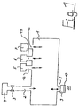
- Fig. 1 is provided at an outlet opening 2 with a compressed air valve 3
- Vehicle unit 4 a separate container 1 connected.
- the separate container 1 with air outlets 12, 13, 14 additionally available vehicle units 5, 6, 7 with locked oil households in line.
- the container 1 has an outlet opening 8 on the output side.
- a throttle point 9 which may only is permeable to an environment 11.
- a filter 10 attached at the throttle point 9 .
- the operation of the separate container 1 is based on first one in vehicle use, for example by clutch actuation resulting, already cleaned exhaust air from the compressed air valve 3 for the cleaning Provide rinsing of the container 1.
- the container 1 cannot according to one here Version shown is a matched to the respective spatial conditions in the vehicle Have shape.
- the container 1 can correspond to an outer contour a vehicle unit 4, 5, 6, 7 and be formed on this outer contour fit in a space-saving manner.
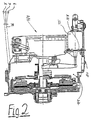
- a servo clutch 4/1 is shown in sections.
- Their 1/1 clutch housing is used for mounting and pressure equalization the originating from the additional vehicle units 5, 6, 7 and via a common manifold 16 introduced at the top of the clutch housing 1/1 Exhaust air.
- clutch booster 15 On the clutch housing 1/1 of the servo clutch 4/1 there is also a clutch booster 15 flanged.
- the exhaust air of the clutch booster 15 via a vent 3/1 in the clutch housing 1/1 can be introduced, so that the interior is always cleaned and dried Air for the piping connected to the coupling housing 1/1 additional vehicle units 5, 6, 7 is kept ready.
- 1 can the number of additional vehicle units that can be connected to the clutch housing 1/1 be expandable with oil budgets.
Landscapes
- Engineering & Computer Science (AREA)
- General Engineering & Computer Science (AREA)
- Mechanical Engineering (AREA)
- Hydraulic Clutches, Magnetic Clutches, Fluid Clutches, And Fluid Joints (AREA)
- General Details Of Gearings (AREA)
- Air-Conditioning For Vehicles (AREA)
Abstract
Die Erfindung betrifft ein Entlüftungssystem für Fahrzeugaggregate (4, 5, 6, 7) mit
Ölhaushalten. Die Fahrzeugaggregate (4, 5, 6, 7) weisen im allgemeinen Entlüftungen
auf, die Druckschwankungen innerhalb der Fahrzeugaggregate (4, 5, 6, 7) mit
der Umgebung ausgleichen. Bei auftretendem Unterdruck in den Fahrzeugaggregaten
können zusammen mit der Umgebungsluft Verunreinigungen in den Innenraum
des jeweiligen Fahrzeugsaggregats angesaugt werden, was dessen Funktion beeinträchtigen
kann. Der Erfindung liegt daher die Aufgabe zugrunde, ein Entlüftungssystem
für Fahrzeugaggregate mit Ölhaushalten zu schaffen, das mit geringem
technischen Aufwand die Funktion der Fahrzeugaggregate dauerhaft garantiert.
Diese Aufgabe wird erfindungsgemäß dadurch gelöst, daß ausgangsseitig eines gereinigte
Druckluft führenden Druckluftventiles (3) eines Fahrzeugaggregates (4) ein
separater Behälter (1) vorgesehen ist, der leitungsmäßig mit Luftauslässen
(12, 13, 14) zusätzlicher Fahrzeugaggregate (5, 6, 7) verbunden ist und der eine
mit einer Umgebung (11) in Verbindung stehende Auslaßöffnung (8) aufweist.

Description
Die Erfindung bezieht sich auf ein Entlüftungssystem für Fahrzeugaggregate mit Ölhaushalten.The invention relates to a ventilation system for vehicle assemblies with oil households.
Fahrzeugaggregate, wie beispielsweise Achsen oder Getriebe, weisen allgemein eine Entlüftung auf, mittels dieser Druckschwankungen im Innenraum der Fahrzeugaggregate mit der Umgebung ausgeglichen werden können. Dabei kann im Falle einer Abkühlung in den Fahrzeugaggregaten, beispielsweise durch deren Kontakt mit kalten Medien, ein Unterdruck entstehen, wodurch Umgebungsluft in die Fahrzeugaggregate eingesaugt wird. Diese Umgebungsluft kann mit Schmutz und/oder Wasser verunreinigt sein und zusammen mit der angesaugten Luft in den Innenraum der Fahrzeugaggregate gelangen, was sich für diese schädigend auswirken kann.Vehicle units, such as axles or transmissions, generally have ventilation, by means of these pressure fluctuations in the interior of the vehicle units can be balanced with the environment. In the case cooling in the vehicle units, for example by their contact With cold media, a negative pressure is created, which creates ambient air in the vehicle units is sucked in. This ambient air can be contaminated with dirt and / or Water should be contaminated and together with the air drawn into the interior of the vehicle aggregates, which can have a damaging effect on them.
Aus der DE 195 23 454 A1 ist eine Belüftungs- und Entlüftungsvorrichtung für Getriebe und Achsen bekannt, bei der für die Be- und Entlüftung jeweils ein separater Belüftungskanal bzw. Entlüftungskanal mit jeweils einer Belüftungs- bzw. Entlüftungsöffnung in einer Gehäusewand vorgesehen ist. Dabei ist der Entlüftungskanal mit einem sich nach außen hin öffnenden Überdruckventil und der Belüftungskanal mit einem sich mit Unterdruck in Richtung des Getriebe- bzw. Achsinneren hin öffnenden, vorgespannten Ventilglied versehen. Der Belüftungskanal ist mit einem zwischen der äußeren Belüftungsöffnung und dem Ventilglied angeordneten, gasdurchlässigen Abdeckglied versehen. Diese Vorrichtung ist technisch relativ aufwendig darstellbar.DE 195 23 454 A1 describes a ventilation and venting device for gears and axes known, in which a separate one for ventilation Ventilation channel or ventilation channel, each with a ventilation or ventilation opening is provided in a housing wall. Here is the ventilation duct with an overpressure valve that opens outwards and the ventilation duct with one with negative pressure in the direction of the gearbox or axle interior provided opening, preloaded valve member. The ventilation duct is with one arranged between the outer ventilation opening and the valve member, provided gas-permeable cover member. This device is technically relative complex to represent.
Der Erfindung liegt die Aufgabe zugrunde, ein Entlüftungssystem für Fahrzeugaggregate mit Ölhaushalten zu schaffen, das bei technisch geringem Aufwand die Funktion der Fahrzeugaggregate dauerhaft garantiert.The invention has for its object a ventilation system for vehicle units to create with oil budgets that with little technical effort Function of the vehicle aggregates guaranteed permanently.
Diese Aufgabe wird erfindungsgemäß durch die Merkmale des Anspruches 1 gelöst. This object is achieved by the features of claim 1.
Durch das Vorsehen eines erfindungsgemäßen separaten Behälters sind zunächst sämtliche Entlüftungsanschlüsse von Fahrzeugaggregaten mit abgeschlossenen Ölhaushalten, wie z. B. Schaltgetriebe, Verteilergetriebe, Achsen, Kupplungen, Bremsen leitungsmäßig zusammenschließbar und über eine im Behälter vorgesehene gemeinsame Auslaßöffnung in die Umgebung entlüftbar. Der Behälter ist dabei mit wenigstens einem, gereinigte Druckluft führenden Druckluftventil eines Fahrzeugaggregates verbunden, so daß die aus dem Druckluftventil entweichende, beispielsweise im Fahrzeugeinsatz entstehende Abluft den Behälter spült. Diese Abluft ist beispielsweise im Falle des Anschlusses des Behälters an die Druckluftaufbereitungsanlage des Fahrzeuges bereits gereinigt und getrocknet. Bei Unterdruck in einem Fahrzeugaggregat kann das hierbei zu ergänzende Volumen an Luft aus der sauberen Behälterluft des Behälters entnommen werden. Ein Eindringen von Wasser und Schmutz in die betreffenden Fahrzeugaggregate bleibt somit wirksam unterbunden. Der leitungsmäßige Anschluß der Luftauslässe der zusätzlichen Fahrzeugaggregate an dem Behälter kann über eine gemeinsame Sammelleitung oder jeweils separat erfolgen.By providing a separate container according to the invention are initially all ventilation connections of vehicle units with closed Oil budgets such as B. manual transmission, transfer case, axles, clutches, Brakes can be connected in line and via one provided in the container common outlet opening can be vented into the environment. The container is there with at least one compressed air valve of a vehicle unit carrying cleaned compressed air connected so that the escaping from the compressed air valve, for example Exhaust air generated in vehicle use rinses the container. This exhaust air is, for example, in the case of connecting the container to the compressed air treatment system of the vehicle already cleaned and dried. With negative pressure In a vehicle unit, the volume of air to be supplemented here be removed from the clean air of the container. An intrusion of Water and dirt in the vehicle units concerned thus remain effective prevented. The line connection of the air outlets of the additional vehicle units on the container can via a common manifold or each done separately.
Gemäß einer weiteren Ausgestaltung der Erfindung, kann an der Auslaßöffnung eine Drosselstelle vorgesehen sein. Durch diese ist ein Schmutzeintrag von der Umgebung in das Innere des Behälters vermieden.According to a further embodiment of the invention, a Throttle point may be provided. Through this is a dirt entry from the environment avoided inside the container.
Gemäß einer weiteren Ausgestaltung der Erfindung kann die Drosselstelle nur in Richtung der Umgebung durchlässig sein. Auf diese Weise ist ein Eindringen verunreinigter Luft in den Behälter und der Fahrzeugaggregate wirksam unterbunden.According to a further embodiment of the invention, the throttle point can only be in Be permeable to the surroundings. In this way, penetration is more contaminated Air in the tank and vehicle units effectively prevented.
Gemäß einer weiteren Ausgestaltung der Erfindung kann anstelle der Drosselstelle oder zusätzlich zu dieser ein Filter installiert sein. Dieser kann unmittelbar an der Drosselstelle angeschlossen sein. Hierdurch kann ein Eindringen verunreinigter Luft in den Behälter reduziert oder vermieden werden. According to a further embodiment of the invention, instead of the throttle point or a filter can be installed in addition to this. This can be directly on the Throttle point must be connected. This can prevent contaminated air from entering reduced or avoided in the container.
Gemäß einer weiteren Ausführung der Erfindung kann das dem Druckluftventil vorgeschaltete Fahrzeugaggregat eine Druckluftaufbereitungsanlage, eine Fahrzeugbremse, eine Servokupplung oder dergleichen sein. Entscheidend für die Arbeitsweise des erfindungsgemäßen Behälters ist die Bereithaltung getrockneter und gereinigter Luft für die zusätzlich am Behälter angeschlossenen Fahrzeugaggregate. Entsprechend des jeweiligen Fahrzeugaggregates kann das mit diesem verbundene Druckluftventil durch ein Kupplungsservoventil, ein Motorwagenbremsventil oder dergleichen gegeben sein.According to a further embodiment of the invention, this can precede the compressed air valve Vehicle unit a compressed air treatment system, a vehicle brake, a servo clutch or the like. Crucial for the way of working of the container according to the invention is the availability of dried and cleaned Air for the additional vehicle units connected to the tank. Depending on the particular vehicle unit, this can be connected to it Compressed air valve through a clutch servo valve, a motor vehicle brake valve or the like.
Gemäß einer weiteren Ausgestaltung der Erfindung können die zusätzlichen Fahrzeugaggregate durch ein Schaltgetriebe, ein Verteilergetriebe, Achsen oder dergleichen gegeben sein.According to a further embodiment of the invention, the additional vehicle units can through a manual transmission, a transfer case, axles or the like be given.
Gemäß einer weiteren Ausgestaltung der Erfindung kann der Behälter eine an die Außenkontur des ihn tragenden Fahrzeugaggregates angepaßte Form aufweisen. Somit beansprucht der Behälter nur geringen Bauraum. Die Befestigung des Behälters an einem Fahrzeugaggregat kann durch eine Verschraubung, Verrastung oder dergleichen realisiert sein.According to a further embodiment of the invention, the container can be attached to the Have the outer contour of the vehicle unit carrying it adapted shape. Thus, the container takes up little space. The attachment of the container on a vehicle unit can be by screwing, locking or the like can be realized.
Der leitungsmäßige Anschluß des Behälters an die jeweiligen Luftauslässe der Fahrzeugaggregate bzw. an das wenigstens eine Druckluftventil, kann durch Steckanschlüsse oder dergleichen realisiert sein.The line connection of the container to the respective air outlets of the Vehicle units or to the at least one compressed air valve can be made by plug connections or the like can be realized.
Gemäß einer weiteren Ausgestaltung der Erfindung kann der Behälter durch das an einem Kupplungskraftverstärker der Servokupplung angeflanschte Kupplungsgehäuse gebildet sein. Somit kann in vorteilhafter Weise die von einer Entlüftung des Kupplungskraftverstärkers entweichende Luft in das Innere des Kupplungsgehäuses geleitet werden. Da der Kupplungskraftverstärker direkt am Kupplungsgehäuse der Servokupplung angeflanscht ist, sind für diesen Anschluß keine zusätzlichen Verbindungsleitungen erforderlich. Auch kann der zusätzliche Behälter zur Bevorratung gesäuberter und getrockneter Luft durch die Nutzung des bereits vorhandenen Kupplungsgehäuses ersatzlos entfallen. In vorteilhafter Weise ist innerhalb des den Druckausgleich für die verschiedenen Fahrzeugaggregate sicherstellenden Kupplungsgehäuses eine hohe Spülhäufigkeit mit gereinigter Luft sichergestellt.According to a further embodiment of the invention, the container can be attached to the Coupling housing flanged to a clutch booster of the servo clutch be educated. Thus, the ventilation of the Clutch booster air escaping into the interior of the clutch housing be directed. Since the clutch booster is located directly on the clutch housing Flanged, there are no additional connecting cables for this connection required. The additional container can also be used for storage cleaned and dried air by using the already existing Coupling housing is not required without replacement. Advantageously, within the Pressure equalization for the various vehicle assemblies ensuring the clutch housing ensures a high flushing frequency with cleaned air.
Gemäß einer weiteren Ausgestaltung der Erfindung können die Luftauslässe der zusätzlichen Fahrzeugaggregate in einer oberseitig des Kupplungsgehäuses angeschlossenen Sammelleitung zusammengeführt sein. Unterseitig des Kupplungsgehäuses kann ein Druckausgleichsventil vorgesehen sein, mittels diesem ein zu hoher Druck im Kupplungsgehäuse abbaubar ist und Kupplungsabrieb sowie andere Schmutzpartikel ausblasbar sind.According to a further embodiment of the invention, the air outlets of the additional vehicle units connected in a top of the clutch housing Collecting line be merged. On the underside of the clutch housing a pressure compensation valve can be provided, by means of which a too high one Pressure in the clutch housing is degradable and clutch abrasion as well as others Dirt particles can be blown out.
Nachstehend ist die erfindungsgemäße Lösung anhand zweier in der Zeichnung dargestellter Ausführungsbeispiele näher erläutert.Below is the solution according to the invention based on two in the drawing illustrated embodiments explained in more detail.
In der Zeichnung zeigen:
- Fig. 1
- schematisch ein Entlüftungssystem für Fahrzeugaggregate mit abgeschlossenen Ölhaushalten und
- Fig. 2
- ausschnittsweise eine Servokupplung als Bestandteil eines Entlüftungssystems gemäß Fig. 1.
- Fig. 1
- schematically a ventilation system for vehicle units with closed oil households and
- Fig. 2
- Detail of a servo clutch as part of a ventilation system according to FIG. 1.
In Fig. 1 ist an einer Auslaßöffnung 2 eines mit einem Druckluftventil 3 versehenen
Fahrzeugaggregates 4 ein separater Behälter 1 angeschlossen. Des weiteren steht
der separate Behälter 1 mit Luftauslässen 12, 13, 14 zusätzlich vorhandener Fahrzeugaggregate
5, 6, 7 mit abgeschlossenen Ölhaushalten leitungsmäßig in Verbindung.
Der Behälter 1 weist ausgangsseitig eine Auslaßöffnung 8 auf. An dieser ist in
der hier gezeigten Version eine Drosselstelle 9 angeordnet, die gegebenenfalls nur
in Richtung einer Umgebung 11 durchlässig ist. An der Drosselstelle 9 ist zusätzlich
ein Filter 10 angebracht. Die Wirkungsweise des separaten Behälters 1 basiert darauf,
zunächst eine im Fahrzeugeinsatz, beispielsweise durch Kupplungsbetätigung
entstehende, bereits gereinigte Abluft aus dem Druckluftventil 3 für die reinigende
Spülung des Behälters 1 vorzusehen. Bei Unterdruck in den genannten Fahrzeug-aggregaten
5, 6, 7, beispielsweise durch Abkühlung ausgelöst, kann diese gereinigte
Abluft bei Bedarf für die Fahrzeugaggregate 5, 6, 7 bereitgestellt werden. Die Anzahl
zusätzlich an den separaten Behälter 1 anschließbarer Fahrzeugaggregate mit
Ölhaushalten ist beliebig erweiterbar. Der Behälter 1 kann gemäß einer hier nicht
gezeigten Version eine auf die jeweiligen Raumverhältnisse im Fahrzeug abgestimmte
Form aufweisen. Dabei kann der Behälter 1 entsprechend einer Außenkontur
eines Fahrzeugaggregates 4, 5, 6, 7 geformt sein und an dieser Außenkontur
raumsparend anliegen.In Fig. 1 is provided at an outlet opening 2 with a
In Fig. 2 ist als Bestandteil eines Entluftungssystems für Fahrzeugaggregate 5, 6, 7
mit abgeschlossenen Ölhaushalten ausschnittsweise eine Servokupplung 4/1 dargestellt.
Deren Kupplungsgehäuse 1/1 dient zur Aufnahme und zum Druckausgleich
der aus den zusätzlichen Fahrzeugaggregaten 5, 6, 7 stammenden und über eine
gemeinsame Sammelleitung 16 an der Oberseite des Kupplungsgehäuses 1/1 eingeleiteten
Abluft.2 is a component of a ventilation system for
An das Kupplungsgehäuse 1/1 der Servorkupplung 4/1 ist des weiteren ein Kupplungskraftverstärker
15 angeflanscht. In dem hier gezeigten Ausführungsbeispiel ist
die Abluft des Kupplungskraftverstärkers 15 über eine Entlüftung 3/1 in das Kupplungsgehäuse
1/1 einleitbar, so daß in dessen Innenraum stets gereinigte und getrocknete
Luft für die an dem Kupplungsgehäuse 1/1 leitungsmäßig angeschlossenen,
zusätzlichen Fahrzeugaggregate 5, 6, 7 bereitgehalten ist. Gemäß Fig. 1 kann
die Anzahl der zusätzlich an das Kupplungsgehäuse 1/1 anschließbaren Fahrzeugaggregate
mit Ölhaushalten beliebig erweiterbar sein.On the clutch housing 1/1 of the servo clutch 4/1 there is also a
Claims (9)
Applications Claiming Priority (4)
| Application Number | Priority Date | Filing Date | Title |
|---|---|---|---|
| DE19736071 | 1997-08-20 | ||
| DE19736071 | 1997-08-20 | ||
| DE19817054 | 1998-04-17 | ||
| DE19817054A DE19817054A1 (en) | 1997-08-20 | 1998-04-17 | Breather system for ancillary units of motor vehicle with enclosed oil sump |
Publications (3)
| Publication Number | Publication Date |
|---|---|
| EP0903475A2 true EP0903475A2 (en) | 1999-03-24 |
| EP0903475A3 EP0903475A3 (en) | 1999-07-14 |
| EP0903475B1 EP0903475B1 (en) | 2002-03-20 |
Family
ID=26039302
Family Applications (1)
| Application Number | Title | Priority Date | Filing Date |
|---|---|---|---|
| EP19980112348 Expired - Lifetime EP0903475B1 (en) | 1997-08-20 | 1998-07-03 | Venting system for oil lubricated vehicle units |
Country Status (1)
| Country | Link |
|---|---|
| EP (1) | EP0903475B1 (en) |
Cited By (1)
| Publication number | Priority date | Publication date | Assignee | Title |
|---|---|---|---|---|
| CN102278457A (en) * | 2010-06-09 | 2011-12-14 | Zf腓德烈斯哈芬股份公司 | Vehicle transmission |
Family Cites Families (2)
| Publication number | Priority date | Publication date | Assignee | Title |
|---|---|---|---|---|
| US3489034A (en) * | 1968-05-17 | 1970-01-13 | Gen Electric | Evacuated gear casing |
| DE19523454B4 (en) * | 1995-06-28 | 2005-05-04 | Zf Friedrichshafen Ag | Ventilation device for gearboxes and axles |
-
1998
- 1998-07-03 EP EP19980112348 patent/EP0903475B1/en not_active Expired - Lifetime
Cited By (3)
| Publication number | Priority date | Publication date | Assignee | Title |
|---|---|---|---|---|
| CN102278457A (en) * | 2010-06-09 | 2011-12-14 | Zf腓德烈斯哈芬股份公司 | Vehicle transmission |
| EP2395263A1 (en) * | 2010-06-09 | 2011-12-14 | ZF Friedrichshafen AG | Vehicle transmission |
| CN102278457B (en) * | 2010-06-09 | 2016-08-03 | Zf腓德烈斯哈芬股份公司 | Transmission for vehicles |
Also Published As
| Publication number | Publication date |
|---|---|
| EP0903475A3 (en) | 1999-07-14 |
| EP0903475B1 (en) | 2002-03-20 |
Similar Documents
| Publication | Publication Date | Title |
|---|---|---|
| EP0818338A3 (en) | Ventilation device for a vehicle cab and filter housing | |
| DE102016223747B4 (en) | Drive arrangement for a vehicle and vehicle with the drive arrangement | |
| DE102019204907A1 (en) | Transmission for a commercial vehicle with a transmission housing with a ventilation arrangement | |
| EP2681015A1 (en) | Robot transmission with a pressure compensation device | |
| DE202006016661U1 (en) | Filter arrangement for brake dust retention systems | |
| DE102019132499A1 (en) | Transmission device for an electrically drivable vehicle, drive device for an electrically drivable vehicle and vehicle | |
| DE102021130151A1 (en) | Drive device for an electrified vehicle axle | |
| DE19523454B4 (en) | Ventilation device for gearboxes and axles | |
| EP2145811B1 (en) | Electric power steering with ventilation | |
| EP0903475B1 (en) | Venting system for oil lubricated vehicle units | |
| DE3942780C1 (en) | ||
| DE102014116043A1 (en) | Outside air filter for vehicle transmission and the like | |
| DE19945897C2 (en) | Gearbox vent structure | |
| DE19817054A1 (en) | Breather system for ancillary units of motor vehicle with enclosed oil sump | |
| DE102007027769A1 (en) | Arrangement of the venting device for a transmission of a motor vehicle | |
| DE10141986A1 (en) | Air filter system for vehicle cabins | |
| EP1320170A2 (en) | Driving and braking device | |
| DE102017005772B4 (en) | Arrangement and method for cleaning a vent hose device, as well as a vehicle | |
| DE102018108135A1 (en) | drive unit | |
| DE102006002606B3 (en) | Dust-free guide table | |
| DE102013103940A1 (en) | cab vehicle | |
| DE102022115786A1 (en) | Drive device with ventilation device | |
| DE102020216287A1 (en) | Transmission device for an electrically driven vehicle | |
| EP1043501B1 (en) | Multistage piston compressor with oil filter | |
| DE102008008173A1 (en) | Electrical controller for being accommodated in engine compartment of motor vehicle, has protection device covering membrane, connecting membrane with environment and preventing direct subjection of membrane with fluid jet |
Legal Events
| Date | Code | Title | Description |
|---|---|---|---|
| PUAI | Public reference made under article 153(3) epc to a published international application that has entered the european phase |
Free format text: ORIGINAL CODE: 0009012 |
|
| AK | Designated contracting states |
Kind code of ref document: A2 Designated state(s): DE FR IT SE |
|
| AX | Request for extension of the european patent |
Free format text: AL;LT;LV;MK;RO;SI |
|
| PUAL | Search report despatched |
Free format text: ORIGINAL CODE: 0009013 |
|
| AK | Designated contracting states |
Kind code of ref document: A3 Designated state(s): AT BE CH CY DE DK ES FI FR GB GR IE IT LI LU MC NL PT SE |
|
| AX | Request for extension of the european patent |
Free format text: AL;LT;LV;MK;RO;SI |
|
| RIC1 | Information provided on ipc code assigned before grant |
Free format text: 6F 01M 13/00 A, 6F 16H 57/02 B |
|
| 17P | Request for examination filed |
Effective date: 19990731 |
|
| AKX | Designation fees paid |
Free format text: DE FR IT SE |
|
| GRAG | Despatch of communication of intention to grant |
Free format text: ORIGINAL CODE: EPIDOS AGRA |
|
| GRAG | Despatch of communication of intention to grant |
Free format text: ORIGINAL CODE: EPIDOS AGRA |
|
| GRAH | Despatch of communication of intention to grant a patent |
Free format text: ORIGINAL CODE: EPIDOS IGRA |
|
| GRAH | Despatch of communication of intention to grant a patent |
Free format text: ORIGINAL CODE: EPIDOS IGRA |
|
| 17Q | First examination report despatched |
Effective date: 20010808 |
|
| GRAA | (expected) grant |
Free format text: ORIGINAL CODE: 0009210 |
|
| AK | Designated contracting states |
Kind code of ref document: B1 Designated state(s): DE FR IT SE |
|
| REF | Corresponds to: |
Ref document number: 59803413 Country of ref document: DE Date of ref document: 20020425 |
|
| PLBE | No opposition filed within time limit |
Free format text: ORIGINAL CODE: 0009261 |
|
| STAA | Information on the status of an ep patent application or granted ep patent |
Free format text: STATUS: NO OPPOSITION FILED WITHIN TIME LIMIT |
|
| 26N | No opposition filed |
Effective date: 20021223 |
|
| PG25 | Lapsed in a contracting state [announced via postgrant information from national office to epo] |
Ref country code: FR Free format text: LAPSE BECAUSE OF NON-PAYMENT OF DUE FEES Effective date: 20040331 |
|
| REG | Reference to a national code |
Ref country code: FR Ref legal event code: ST |
|
| REG | Reference to a national code |
Ref country code: FR Ref legal event code: D3 |
|
| PGFP | Annual fee paid to national office [announced via postgrant information from national office to epo] |
Ref country code: FR Payment date: 20090716 Year of fee payment: 12 |
|
| PGFP | Annual fee paid to national office [announced via postgrant information from national office to epo] |
Ref country code: SE Payment date: 20090715 Year of fee payment: 12 Ref country code: DE Payment date: 20090722 Year of fee payment: 12 |
|
| PGFP | Annual fee paid to national office [announced via postgrant information from national office to epo] |
Ref country code: IT Payment date: 20090725 Year of fee payment: 12 |
|
| REG | Reference to a national code |
Ref country code: FR Ref legal event code: ST Effective date: 20110331 |
|
| PG25 | Lapsed in a contracting state [announced via postgrant information from national office to epo] |
Ref country code: DE Free format text: LAPSE BECAUSE OF NON-PAYMENT OF DUE FEES Effective date: 20110201 |
|
| REG | Reference to a national code |
Ref country code: DE Ref legal event code: R119 Ref document number: 59803413 Country of ref document: DE Effective date: 20110201 |
|
| PG25 | Lapsed in a contracting state [announced via postgrant information from national office to epo] |
Ref country code: IT Free format text: LAPSE BECAUSE OF NON-PAYMENT OF DUE FEES Effective date: 20100703 |
|
| PG25 | Lapsed in a contracting state [announced via postgrant information from national office to epo] |
Ref country code: SE Free format text: LAPSE BECAUSE OF NON-PAYMENT OF DUE FEES Effective date: 20100704 |
|
| PG25 | Lapsed in a contracting state [announced via postgrant information from national office to epo] |
Ref country code: FR Free format text: LAPSE BECAUSE OF NON-PAYMENT OF DUE FEES Effective date: 20100731 |