EP0903469B1 - Procédé de régulation de la puissance d'un groupe à turbine et dispositif pour la réalisation du procédé - Google Patents
Procédé de régulation de la puissance d'un groupe à turbine et dispositif pour la réalisation du procédé Download PDFInfo
- Publication number
- EP0903469B1 EP0903469B1 EP97810694A EP97810694A EP0903469B1 EP 0903469 B1 EP0903469 B1 EP 0903469B1 EP 97810694 A EP97810694 A EP 97810694A EP 97810694 A EP97810694 A EP 97810694A EP 0903469 B1 EP0903469 B1 EP 0903469B1
- Authority
- EP
- European Patent Office
- Prior art keywords
- power
- shaft
- turbine
- kin
- generator
- Prior art date
- Legal status (The legal status is an assumption and is not a legal conclusion. Google has not performed a legal analysis and makes no representation as to the accuracy of the status listed.)
- Expired - Lifetime
Links
- 238000000034 method Methods 0.000 title claims description 26
- 238000002485 combustion reaction Methods 0.000 claims description 21
- 230000001105 regulatory effect Effects 0.000 claims description 15
- 230000001133 acceleration Effects 0.000 claims description 9
- 239000000446 fuel Substances 0.000 claims description 8
- 238000002955 isolation Methods 0.000 claims 1
- 238000010586 diagram Methods 0.000 description 4
- 238000005259 measurement Methods 0.000 description 3
- 230000002123 temporal effect Effects 0.000 description 3
- 230000003321 amplification Effects 0.000 description 2
- 238000003199 nucleic acid amplification method Methods 0.000 description 2
- 230000000903 blocking effect Effects 0.000 description 1
- 230000006735 deficit Effects 0.000 description 1
- 230000001419 dependent effect Effects 0.000 description 1
- 230000004069 differentiation Effects 0.000 description 1
- 238000005516 engineering process Methods 0.000 description 1
- 230000000977 initiatory effect Effects 0.000 description 1
- 238000009413 insulation Methods 0.000 description 1
- 230000003993 interaction Effects 0.000 description 1
- 230000007257 malfunction Effects 0.000 description 1
- 230000001681 protective effect Effects 0.000 description 1
- 238000000926 separation method Methods 0.000 description 1
- 230000001360 synchronised effect Effects 0.000 description 1
- 230000001960 triggered effect Effects 0.000 description 1
Images
Classifications
-
- F—MECHANICAL ENGINEERING; LIGHTING; HEATING; WEAPONS; BLASTING
- F02—COMBUSTION ENGINES; HOT-GAS OR COMBUSTION-PRODUCT ENGINE PLANTS
- F02C—GAS-TURBINE PLANTS; AIR INTAKES FOR JET-PROPULSION PLANTS; CONTROLLING FUEL SUPPLY IN AIR-BREATHING JET-PROPULSION PLANTS
- F02C9/00—Controlling gas-turbine plants; Controlling fuel supply in air- breathing jet-propulsion plants
- F02C9/48—Control of fuel supply conjointly with another control of the plant
- F02C9/50—Control of fuel supply conjointly with another control of the plant with control of working fluid flow
- F02C9/54—Control of fuel supply conjointly with another control of the plant with control of working fluid flow by throttling the working fluid, by adjusting vanes
-
- F—MECHANICAL ENGINEERING; LIGHTING; HEATING; WEAPONS; BLASTING
- F01—MACHINES OR ENGINES IN GENERAL; ENGINE PLANTS IN GENERAL; STEAM ENGINES
- F01D—NON-POSITIVE DISPLACEMENT MACHINES OR ENGINES, e.g. STEAM TURBINES
- F01D17/00—Regulating or controlling by varying flow
- F01D17/02—Arrangement of sensing elements
- F01D17/04—Arrangement of sensing elements responsive to load
-
- F—MECHANICAL ENGINEERING; LIGHTING; HEATING; WEAPONS; BLASTING
- F01—MACHINES OR ENGINES IN GENERAL; ENGINE PLANTS IN GENERAL; STEAM ENGINES
- F01D—NON-POSITIVE DISPLACEMENT MACHINES OR ENGINES, e.g. STEAM TURBINES
- F01D17/00—Regulating or controlling by varying flow
- F01D17/02—Arrangement of sensing elements
- F01D17/06—Arrangement of sensing elements responsive to speed
-
- H—ELECTRICITY
- H02—GENERATION; CONVERSION OR DISTRIBUTION OF ELECTRIC POWER
- H02P—CONTROL OR REGULATION OF ELECTRIC MOTORS, ELECTRIC GENERATORS OR DYNAMO-ELECTRIC CONVERTERS; CONTROLLING TRANSFORMERS, REACTORS OR CHOKE COILS
- H02P9/00—Arrangements for controlling electric generators for the purpose of obtaining a desired output
- H02P9/04—Control effected upon non-electric prime mover and dependent upon electric output value of the generator
-
- F—MECHANICAL ENGINEERING; LIGHTING; HEATING; WEAPONS; BLASTING
- F05—INDEXING SCHEMES RELATING TO ENGINES OR PUMPS IN VARIOUS SUBCLASSES OF CLASSES F01-F04
- F05D—INDEXING SCHEME FOR ASPECTS RELATING TO NON-POSITIVE-DISPLACEMENT MACHINES OR ENGINES, GAS-TURBINES OR JET-PROPULSION PLANTS
- F05D2200/00—Mathematical features
- F05D2200/10—Basic functions
- F05D2200/11—Sum
-
- F—MECHANICAL ENGINEERING; LIGHTING; HEATING; WEAPONS; BLASTING
- F05—INDEXING SCHEMES RELATING TO ENGINES OR PUMPS IN VARIOUS SUBCLASSES OF CLASSES F01-F04
- F05D—INDEXING SCHEME FOR ASPECTS RELATING TO NON-POSITIVE-DISPLACEMENT MACHINES OR ENGINES, GAS-TURBINES OR JET-PROPULSION PLANTS
- F05D2270/00—Control
- F05D2270/01—Purpose of the control system
- F05D2270/05—Purpose of the control system to affect the output of the engine
- F05D2270/053—Explicitly mentioned power
-
- F—MECHANICAL ENGINEERING; LIGHTING; HEATING; WEAPONS; BLASTING
- F05—INDEXING SCHEMES RELATING TO ENGINES OR PUMPS IN VARIOUS SUBCLASSES OF CLASSES F01-F04
- F05D—INDEXING SCHEME FOR ASPECTS RELATING TO NON-POSITIVE-DISPLACEMENT MACHINES OR ENGINES, GAS-TURBINES OR JET-PROPULSION PLANTS
- F05D2270/00—Control
- F05D2270/01—Purpose of the control system
- F05D2270/06—Purpose of the control system to match engine to driven device
- F05D2270/061—Purpose of the control system to match engine to driven device in particular the electrical frequency of driven generator
-
- F—MECHANICAL ENGINEERING; LIGHTING; HEATING; WEAPONS; BLASTING
- F05—INDEXING SCHEMES RELATING TO ENGINES OR PUMPS IN VARIOUS SUBCLASSES OF CLASSES F01-F04
- F05D—INDEXING SCHEME FOR ASPECTS RELATING TO NON-POSITIVE-DISPLACEMENT MACHINES OR ENGINES, GAS-TURBINES OR JET-PROPULSION PLANTS
- F05D2270/00—Control
- F05D2270/30—Control parameters, e.g. input parameters
- F05D2270/304—Spool rotational speed
Definitions
- the present invention relates to the field of Power plant technology. It concerns a procedure for regulation the power of a thermal power in electrical power converting turbo group, which turbo group on one common shaft driven by thermal power Turbine and one driven by the turbine, electrical power to a generator supplying a network which method is used by the generator electrical power output determined and the thermal Power for the turbine depending on the measured electrical power is regulated.
- the invention further relates to a device for performing of the method, comprising a power controller for Regulation of the thermal power for the turbine, as well as first Means having an output power of the turbo group compare a predetermined power value and a difference value pass on to the power controller as a control signal.
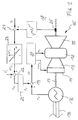
- FIG. 1 An exemplary circuit diagram for such a known power control is shown in FIG. 1.
- the output of a turbo group 10 consisting of a gas turbine system 15 and a generator 16 is regulated.
- the gas turbine system 15 comprises the actual turbine 11, a combustion chamber 12, a compressor 13 and a controllable inlet 14 for the combustion air, which usually consists of adjustable inlet guide vanes ( V ariable I nlet G uiding V anes VIGVs) exists.
- Turbine 11 and generator 16 sit on a common shaft 17, the rotational frequency f of which is measured by means of a rotational frequency transmitter 25.
- the generator 16 outputs the generated electrical power P G to a network 18, usually a three-phase network.
- the electrical power P G of the generator 16 is compared in a subtractor 19 with a predetermined power value P C and the difference value ⁇ P is fed to a power controller 20 which in turn controls the amount of combustion air supplied to the compressor 13 and the mass flow dm fc via the controllable inlet 14 / dt of the fuel supplied to the combustion chamber 12 controls.
- a rise limiter 21 is provided which limits the rate of change of the control signal.
- the control circuit shown in FIG. 1 can lead to a possibly dangerous behavior of the gas turbine if strong (positive or negative) accelerations of the shaft occur.
- the measured (electrical) output power P G turbo group is no longer a measure of the generated thermal power P T of the gas turbine 15, which is determined by the mass flows of the combustion air and the fuel, but also contains a significant proportion of kinetic power.
- the resulting inequality between the measured output power and the generated thermal power can lead to the power control initiating (in itself unjustified) changes in the mass flows of the combustion air and the fuel, which are dangerous for the gas turbine itself and / or the stability of the connected network can.
- the generator switch also opens, the measured electrical power P G at the generator drops to zero since there is no power flow into the network. In this case too, there is an inequality between the measured output power and the generated thermal power, and the power control receives incorrect information about the thermal state of the gas turbine, which leads to undesired behavior of the power controller.
- the measurement of the electrical output power P G is generally not a direct measure of the thermal power on the gas turbine, but a measure of the total power on the shaft, and includes kinetic power that is given or absorbed when the shaft is braked or accelerated.
- EP 0742356 A2 describes a method for setting a Main controlled variable when operating a gas turbine group.
- the main controlled variable can be, for example Generator power or the rotational frequency of the rotor are used.
- a setpoint of the selected main controlled variable is shown with a Measured value of the main control variable compared, and a required
- the main rule difference is hierarchically based on management distributed at least one cascade.
- a gas turbine group with sequential combustion should preferably proceed in such a way that initially the potential of a first power-temperature cascade, which the fuel mass flow into the first combustion chamber sets until a maximum turbine inlet temperature is reached is exhausted, and then that Potential of a second power-temperature cascade for the second combustion chamber is exhausted and then that of Power pressure cascade.
- main control difference By distributing the main control difference separate cascades become one mutual interaction of the cascades excluded.
- main controlled variable controller and Size controller within the cascade is the size controller always ready to respond. This makes the scheme fast and certainly with a view to excluding one another Exertion of influence. Still, if you limit yourself to The main control variables mentioned are power and rotational frequency the aforementioned disadvantages are not reliably excluded become.
- a method for protecting a turbomachine from a dangerous increase in the rotor frequency during load shedding is described in SU 1149037 A based on the operation of a steam turbine system. This method is based on three output variables, the measured electrical generator power N ⁇ , the rotational frequency n of the rotor and the effective mechanical turbine power N T , which are measured indirectly using the measured pressure parameters p 1 ; p 2 ; p 3 of the process steam and coefficients K 1 not explained in more detail; K 2 ; K 3 is determined by calculation in an adder (1).
- N T -N ⁇ I ⁇ n ⁇ dn / dt, where I symbolize the moment of inertia of the rotating mass of the rotor and dn / dt its acceleration , the kinetic power I ⁇ n ⁇ dn / dt of the rotating rotor is calculated.
- An adder (6) links the signals corresponding to the rotational frequency and the kinetic power. As soon as the sum of these signals exceeds a predetermined limit value (comparator (7)), a warning signal is output by the pulse shaper (8) to the logic module (12).
- the generator power N ⁇ is conducted via comparators (9) and (10).
- pulse shaper (11) outputs a warning signal to the logic module (12). If warning signals are received at the logic module (12) from both cascades at the same time, a protective signal is triggered which causes the steam supply to the turbine to be shut off.
- This method is not designed as a power control of a turbo group, but rather as a method for protecting turbo groups against mechanical overload during load shedding.
- the electrical power at the terminals of the generator can be measured.
- Another one, from the generator independent type of measurement is preferred according to a second Embodiment of the invention characterized in that to determine the electrical output from the generator Power the rotational frequency of the shaft and that at the Shaft attacking torque measured and from these sizes the electrical power is calculated.
- the moment of inertia ⁇ of the shaft is included in the determination of the kinetic power of the shaft.
- the moment of inertia can be calculated or also determined experimentally.
- a preferred embodiment of the device according to the invention is characterized in that the third means a differentiator, a multiplier and an amplifier with an adjustable gain factor.
- the method is applied to a turbo group, which includes a steam turbine or a gas turbine, or on a combined cycle power plant, which has a gas turbine and a steam turbine connected behind the gas turbine.
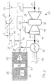
- FIG. 2 shows a power control for a gas turbine 15 in a schematic circuit diagram analogous to FIG. 1, which is based on a preferred exemplary embodiment of the method according to the invention.
- the gas turbine system 15 with its parts 11, .., 14, the shaft 17, the generator 16 connected to a network 18, and the control loop formed from the elements 19, .., 25 are essentially the same as in FIG. 1, and therefore provided with the same reference numerals.
- a change compared to FIG. 1 results in that the measured electrical power P G from the generator 16 is not compared directly at the subtractor 19 with the predetermined power target value P C , but that the electrical power P G is initially compared in an adder 30 kinetic power P kin is added.
- the kinetic power P kin is calculated in a correction circuit 26 from the rotational frequency f of the shaft 17 measured on the shaft 17 in accordance with equation (2).
- the measured rotational frequency f is applied to an input of a multiplier 28 provided with two inputs.
- the temporal change df / dt of the rotational frequency f which is derived from the measured rotational frequency f by differentiation in a differentiator 27, is applied to the other input of the multiplier 28.
- the product of the quantities f and df / dt calculated in the multiplier 28 is then amplified in an amplifier 29 which has the amplification factor 4 ⁇ 2 ⁇ .
- the correction circuit 26 of the exemplary embodiment represents an analog computing circuit which calculates the desired kinetic power P kin from the measured rotational frequency f.
- this calculation can also be carried out digitally by means of a microprocessor or the like if the input variables are digitized accordingly beforehand.
- the rotation frequency f is measured in FIG. 2 by means of a separate rotation frequency transmitter 25 '.
- this separate rotary frequency transmitter 25 ' can be dispensed with and the output signal of the rotary frequency transmitter 25 can be used for the calculation of the kinetic power.
- the sum of the electrical power P G and the kinetic power P kin formed in the adder 30 is compared in the subtractor 19 with a predetermined power value P C and the thermal power P T is reduced if the difference value ⁇ P is positive, or increased if the difference value ⁇ P is negative.
- a gas turbine system 15 which comprises a controllable inlet 14 for the combustion air, a compressor 13 for compressing the combustion air, a combustion chamber 12 for burning a fuel while supplying the combustion air, and a turbine 11, the thermal power P T the mass flow of the intake combustion air via the controllable inlet 14, and the mass flow of the fuel dm fc / dt regulated.
- the electrical power P G for the power control is taken directly from the output terminals of the generator 16. If such a measurement on the generator 16 is to be dispensed with, the rotational frequency f of the shaft 17 and the torque acting on the shaft 17 can be measured to determine the electrical power P G output by the generator 16, and the electrical power P G can be calculated from these variables. In this way, insulation problems on the generator side can be avoided, for example.
- the electrical power P G is set to zero by disconnecting the generator 16 from the network 18 during a stationary operation of the turbo group 10 at a time.
- the rotational frequency f and rotational acceleration df / dt of the shaft 17 present at this time are measured and, for example, input into the correction circuit 26.
- the regulation procedure described can be applied to individual Turbo groups or a combination of several of Apply turbo groups.
- the turbine can - as explained in the Example - be a gas turbine. But it can also be a steam turbine.
- inventive Use procedures in combined cycle power plants, which at least one gas turbine and at least one behind the Gas turbine switched steam turbine include.
Landscapes
- Engineering & Computer Science (AREA)
- Mechanical Engineering (AREA)
- General Engineering & Computer Science (AREA)
- Chemical & Material Sciences (AREA)
- Combustion & Propulsion (AREA)
- Physics & Mathematics (AREA)
- Fluid Mechanics (AREA)
- Power Engineering (AREA)
- Control Of Eletrric Generators (AREA)
- Control Of Turbines (AREA)
- Engine Equipment That Uses Special Cycles (AREA)
Claims (8)
- Procédé de régulation de la puissance d'un groupe à turbine (10) convertissant une puissance thermique en une puissance électrique, groupe à turbine (10) qui comprend, sur un arbre commun (17), une turbine (11) entraínée par la puissance thermique et un générateur (16) entraíné par la turbine (11) et fournissant une puissance électrique PG à un réseau (18), procédé dans lequel on détermine la puissance électrique PG fournie par le générateur (16) et la puissance cinétique Pcin absorbée, respectivement fournie par l'arbre (17) et on régule la puissance thermique PT pour la turbine (11) en fonction de la puissance électrique PG et de la puissance cinétique Pcin, caractérisé en ce que l'on détecte la puissance électrique PG et la fréquence de rotation f de l'arbre (17), on détermine la puissance cinétique Pcin de l'arbre (17) à partir de la fréquence de rotation f et de la variation temporelle df/dt de la fréquence de rotation f selon l'équation Pcin = 4π2··f·df/dt (dans laquelle symbolise le moment d'inertie de la masse en rotation), on additionne la puissance cinétique Pcin de l'arbre (17) et la puissance électrique PG, on compare la somme de la puissance électrique PG et de la puissance cinétique Pcin avec une valeur de puissance prédéterminée PC, et on transmet la valeur différentielle détectée ΔP à un régulateur de puissance (20) en vue de la régulation de la puissance thermique PT de la turbine (11).
- Procédé suivant la revendication 1, caractérisé en ce que l'on réduit la puissance thermique PT lorsque la valeur différentielle détectée ΔP est positive, et on l'augmente lorsque la valeur différentielle ΔP est négative.
- Procédé suivant la revendication 1, caractérisé en ce que la turbine (11) fait partie d'une installation de turbine à gaz (15), installation de turbine à gaz (15) qui comprend une entrée réglable (14) pour l'air de combustion, un compresseur (13) pour la compression de l'air de combustion, une chambre de combustion (12) pour la combustion d'un combustible avec apport de l'air de combustion et la turbine (11), et en ce que, pour la régulation de la puissance thermique PT, on régule le courant massique de l'air de combustion entrant au moyen de l'entrée réglable (14) et le courant massique de combustible dmfc/dt.
- Procédé suivant la revendication 1, caractérisé en ce que, pour la détermination de la puissance électrique PG fournie par le générateur (16), on mesure la fréquence de rotation f de l'arbre (17) et le couple de rotation attaquant l'arbre (17) et on calcule la puissance électrique PG à partir de ces grandeurs.
- Procédé suivant la revendication 4, caractérisé en ce que, pour la fixation du moment d'inertie de l'arbre (17) déterminant pour la régulation, on amène la puissance électrique PG à zéro en séparant le générateur (16) du réseau (18) à un instant donné dans un domaine stationnaire du groupe à turbine (10) et on mesure la fréquence de rotation f et l'accélération angulaire df/dt de l'arbre (17) à cet instant, et en ce que l'on choisit la valeur du moment d'inertie de l'arbre (17) de telle façon que la puissance cinétique Pcin calculée par l'équation Pcin = 4π2··f·(df/dt) soit égale à la puissance électrique PG à l'instant de la séparation.
- Dispositif pour la mise en oeuvre du procédé de régulation de la puissance d'un groupe à turbine (10) convertissant une puissance thermique en une puissance électrique, groupe à turbine (10) qui comprend, sur un arbre commun (17), une turbine (11) entraínée par la puissance thermique et un générateur (16) entraíné par la turbine (11) et fournissant une puissance électrique PG à un réseau (18), ainsi qu'un régulateur de puissance (20) en vue de la régulation de la puissance thermique PT pour la turbine (11), caractérisé par des premiers moyens (19), qui comparent une puissance de sortie du groupe à turbine (10) avec une valeur de puissance prédéterminée PC et transmettent une valeur différentielle ΔP comme signal de commande au régulateur de puissance (20) en vue de la régulation de la puissance thermique PT pour la turbine (11), des deuxièmes moyens (25, 25') pour la mesure de la fréquence de rotation f de l'arbre (17), des troisièmes moyens (26, ..., 29), qui déterminent la puissance cinétique Pcin de l'arbre (17) à partir de la fréquence de rotation mesurée f et de la variation temporelle df/dt de la fréquence de rotation f selon l'équation Pcin = 4π2··f·(df/dt) (dans laquelle symbolise le moment d'inertie de la masse en rotation (17)), et des quatrièmes moyens (30), qui additionnent la puissance électrique PG fournie par le générateur (16) et la puissance cinétique Pcin déterminée par les troisièmes moyens (26, ..., 29), et la transmettent comme puissance de sortie du groupe à turbine (10) aux premiers moyens (19).
- Dispositif suivant la revendication 6, caractérisé en ce que les troisièmes moyens comprennent un module de différentiation (27), un module de multiplication (28) et un amplificateur (29) avec un facteur d'amplification réglable.
- Dispositif suivant la revendication 6 ou 7, caractérisé en ce que les premiers moyens comprennent un module de soustraction (19), les deuxièmes moyens un capteur de fréquence de rotation (25, 25') et les quatrièmes moyens un module d'addition (30).
Priority Applications (7)
| Application Number | Priority Date | Filing Date | Title |
|---|---|---|---|
| EP97810694A EP0903469B1 (fr) | 1997-09-22 | 1997-09-22 | Procédé de régulation de la puissance d'un groupe à turbine et dispositif pour la réalisation du procédé |
| DE59708625T DE59708625D1 (de) | 1997-09-22 | 1997-09-22 | Verfahren zur Regelung der Leistung einer Turbogruppe und Vorrichtung zur Durchführung des Verfahrens |
| TW087114139A TW402662B (en) | 1997-09-22 | 1998-08-27 | Method for regulating the power of a turbo set, device for carrying out the method and use of the method |
| US09/153,020 US6216437B1 (en) | 1997-09-22 | 1998-09-15 | Method for regulating the power of a turbo set |
| MYPI98004233A MY124581A (en) | 1997-09-22 | 1998-09-16 | Method for controlling the power of a turbine plant and device for implementing the method |
| JP26681598A JP4199856B2 (ja) | 1997-09-22 | 1998-09-21 | ターボ群の出力の調整方法および装置およびターボ群の出力の調整方法の用途 |
| CN98120341A CN1113154C (zh) | 1997-09-22 | 1998-09-21 | 涡轮机组功率调节方法及实现该方法的设备 |
Applications Claiming Priority (1)
| Application Number | Priority Date | Filing Date | Title |
|---|---|---|---|
| EP97810694A EP0903469B1 (fr) | 1997-09-22 | 1997-09-22 | Procédé de régulation de la puissance d'un groupe à turbine et dispositif pour la réalisation du procédé |
Publications (2)
| Publication Number | Publication Date |
|---|---|
| EP0903469A1 EP0903469A1 (fr) | 1999-03-24 |
| EP0903469B1 true EP0903469B1 (fr) | 2002-10-30 |
Family
ID=8230400
Family Applications (1)
| Application Number | Title | Priority Date | Filing Date |
|---|---|---|---|
| EP97810694A Expired - Lifetime EP0903469B1 (fr) | 1997-09-22 | 1997-09-22 | Procédé de régulation de la puissance d'un groupe à turbine et dispositif pour la réalisation du procédé |
Country Status (7)
| Country | Link |
|---|---|
| US (1) | US6216437B1 (fr) |
| EP (1) | EP0903469B1 (fr) |
| JP (1) | JP4199856B2 (fr) |
| CN (1) | CN1113154C (fr) |
| DE (1) | DE59708625D1 (fr) |
| MY (1) | MY124581A (fr) |
| TW (1) | TW402662B (fr) |
Families Citing this family (22)
| Publication number | Priority date | Publication date | Assignee | Title |
|---|---|---|---|---|
| US6380639B1 (en) * | 2000-05-11 | 2002-04-30 | Bombardier Inc. | System, method and apparatus for power regulation |
| DE10050248A1 (de) * | 2000-10-11 | 2002-04-18 | Alstom Switzerland Ltd | Brenner |
| US6474069B1 (en) * | 2000-10-18 | 2002-11-05 | General Electric Company | Gas turbine having combined cycle power augmentation |
| US6897577B2 (en) * | 2003-07-14 | 2005-05-24 | General Electric Company | Methods and system for power generation |
| EP2038517B8 (fr) | 2006-07-06 | 2016-09-14 | General Electric Technology GmbH | Procédé pour faire fonctionner une turbine à gaz et turbine à gaz permettant la mise en oeuvre du procédé |
| EP2292910B1 (fr) * | 2009-07-21 | 2016-02-10 | Alstom Technology Ltd | Procédé de contrôle de turbine à gaz |
| JP5716183B2 (ja) * | 2010-11-02 | 2015-05-13 | 三菱日立パワーシステムズ株式会社 | 発電システム及び発電システムの制御方法 |
| FR2971815B1 (fr) | 2011-02-21 | 2015-07-24 | Turbomeca | Dispositif et procede d'injection privilegiee |
| DE102011088524A1 (de) * | 2011-12-14 | 2013-06-20 | Siemens Aktiengesellschaft | Verfahren zum Stabilisieren einer Netzfrequenz mit einer Gasturbine im Brennstoffmischbetrieb |
| US9002615B2 (en) * | 2012-01-18 | 2015-04-07 | General Electric Company | Methods and systems for managing power of an engine |
| EP2772742A1 (fr) * | 2013-02-27 | 2014-09-03 | Siemens Aktiengesellschaft | Procédé de détermination de puissance et turbomachine |
| US9638101B1 (en) * | 2013-03-14 | 2017-05-02 | Tucson Embedded Systems, Inc. | System and method for automatically controlling one or multiple turbogenerators |
| US20150033750A1 (en) * | 2013-07-31 | 2015-02-05 | General Electric Company | Gas turbine system control adjustment for gas turbine shaft speed change |
| TWI500231B (zh) * | 2013-08-19 | 2015-09-11 | Univ Nat Cheng Kung | 發電系統及方法 |
| US9771823B2 (en) * | 2014-06-26 | 2017-09-26 | General Electric Company | Power generation system control following transient grid event |
| GB201412473D0 (en) * | 2014-07-14 | 2014-08-27 | Rolls Royce Plc | Shaft stiffness |
| AT516817B1 (de) * | 2015-01-23 | 2025-12-15 | Innio Jenbacher Gmbh & Co Og | Verfahren zum Betreiben einer Anordnung umfassend eine rotierende Arbeitsmaschine |
| EP3208936A1 (fr) * | 2016-02-16 | 2017-08-23 | General Electric Technology GmbH | Procédé et dispositif de commande de générateur |
| US10205414B2 (en) * | 2016-05-24 | 2019-02-12 | General Electric Company | Systems and methods for adjusting operations of a gas turbine following a transient event |
| EP3301267A1 (fr) * | 2016-09-29 | 2018-04-04 | Siemens Aktiengesellschaft | Procédé de fonctionnement d'un turbo-générateur et le dispositif |
| US10337348B2 (en) * | 2017-03-27 | 2019-07-02 | General Electric Company | Systems and methods for controlling a power generation system |
| US11056989B1 (en) | 2020-06-15 | 2021-07-06 | General Electric Company | Operation of power plant at transient loads during switching event on transmission lines |
Citations (1)
| Publication number | Priority date | Publication date | Assignee | Title |
|---|---|---|---|---|
| EP0742356A2 (fr) * | 1995-05-08 | 1996-11-13 | ABB Management AG | Méthode à établir un paramètre pour la régulation d'une turbine à gaz |
Family Cites Families (11)
| Publication number | Priority date | Publication date | Assignee | Title |
|---|---|---|---|---|
| US3898842A (en) * | 1972-01-27 | 1975-08-12 | Westinghouse Electric Corp | Electric power plant system and method for operating a steam turbine especially of the nuclear type with electronic reheat control of a cycle steam reheater |
| US4242592A (en) * | 1977-10-11 | 1980-12-30 | Westinghouse Electric Corp. | Gas turbine power plant control apparatus including an ambient temperature responsive control system |
| US4625510A (en) * | 1981-04-24 | 1986-12-02 | Bendix Avelex Inc. | Stress limiter apparatus for a gas turbine engine |
| US4425510A (en) * | 1982-06-01 | 1984-01-10 | Jury Webster W | Method and apparatus for tidal generation of power |
| JPS59142603A (ja) * | 1983-02-01 | 1984-08-15 | Sanyo Denki Kk | 高ゲインフイ−ドバツク制御系 |
| US4522026A (en) * | 1983-02-07 | 1985-06-11 | Pratt & Whitney Canada Inc. | Power/torque limiter unit for free turbine type engines |
| US4529887A (en) * | 1983-06-20 | 1985-07-16 | General Electric Company | Rapid power response turbine |
| SU1149037A1 (ru) * | 1983-11-22 | 1985-04-07 | Производственное Предприятие "Уралтехэнерго" Производственного Объединения По Наладке,Совершенствованию Технологии И Эксплуатации Электростанций И Сетей "Союзтехэнерго" | Способ защиты турбомашины при сбросе нагрузки |
| US4638173A (en) * | 1985-05-14 | 1987-01-20 | The United States Of America As Represented By The Secretary Of The Navy | Electromechanical power source |
| SE469758B (sv) * | 1992-01-29 | 1993-09-06 | Asea Brown Boveri | Foerfarande foer styrning av effekt alstrad av en gasturbin samt anordning foer genomfoerande av foerfarandet |
| US5896736A (en) * | 1997-03-06 | 1999-04-27 | General Electric Company | Load rejection rapid acting fuel-air controller for gas turbine |
-
1997
- 1997-09-22 DE DE59708625T patent/DE59708625D1/de not_active Expired - Lifetime
- 1997-09-22 EP EP97810694A patent/EP0903469B1/fr not_active Expired - Lifetime
-
1998
- 1998-08-27 TW TW087114139A patent/TW402662B/zh not_active IP Right Cessation
- 1998-09-15 US US09/153,020 patent/US6216437B1/en not_active Expired - Lifetime
- 1998-09-16 MY MYPI98004233A patent/MY124581A/en unknown
- 1998-09-21 CN CN98120341A patent/CN1113154C/zh not_active Expired - Lifetime
- 1998-09-21 JP JP26681598A patent/JP4199856B2/ja not_active Expired - Lifetime
Patent Citations (1)
| Publication number | Priority date | Publication date | Assignee | Title |
|---|---|---|---|---|
| EP0742356A2 (fr) * | 1995-05-08 | 1996-11-13 | ABB Management AG | Méthode à établir un paramètre pour la régulation d'une turbine à gaz |
Also Published As
| Publication number | Publication date |
|---|---|
| CN1216338A (zh) | 1999-05-12 |
| DE59708625D1 (de) | 2002-12-05 |
| JPH11153004A (ja) | 1999-06-08 |
| MY124581A (en) | 2006-06-30 |
| CN1113154C (zh) | 2003-07-02 |
| EP0903469A1 (fr) | 1999-03-24 |
| TW402662B (en) | 2000-08-21 |
| JP4199856B2 (ja) | 2008-12-24 |
| US6216437B1 (en) | 2001-04-17 |
Similar Documents
| Publication | Publication Date | Title |
|---|---|---|
| EP0903469B1 (fr) | Procédé de régulation de la puissance d'un groupe à turbine et dispositif pour la réalisation du procédé | |
| DE3308566C2 (fr) | ||
| EP2038517B1 (fr) | Procédé pour faire fonctionner une turbine à gaz et turbine à gaz permettant la mise en oeuvre du procédé | |
| DE2922972C2 (de) | Windturbinenregelsystem | |
| DE60029660T2 (de) | Gasturbinenkraftzentrale mit Regelung der Reservekapazität | |
| DE60121679T2 (de) | Regeleinrichtung für eine Dampfturbine, die variable Frequenzregelung erlaubt | |
| DE2914595C2 (de) | Einrichtung zum Regeln des Drehmoments eines Asynchron-Wechselstrommotors | |
| CH701506A1 (de) | Verfahren zum frühzeitigen Erkennen und vorausschauenden Beherrschen von verbraucherseitigen Lastabwürfen in einem elektrischen Netz sowie Vorrichtung zur Durchführung des Verfahrens. | |
| EP2118997B1 (fr) | Procédé de fonctionnement d'une centrale électrique | |
| DE2635993C3 (de) | Brennstoffregelung für eine Gasturbinenanlage | |
| DE10136974A1 (de) | Verfahren zum Betreiben einer Windenergieanlage | |
| DE102010014165A1 (de) | Dynamische Trägheitsregelung | |
| DE2902697A1 (de) | Verfahren und vorrichtung zur steuerung des schubs eines gasturbinentriebwerks | |
| EP2093419A2 (fr) | Procédé de régulation d'une éolienne et éolienne | |
| DE3422210A1 (de) | Verfahren und anordnung zum steuern einer turbine | |
| EP2764239B1 (fr) | Procédé servant à faire fonctionner une éolienne et éolienne correspondante | |
| US4292534A (en) | Power and speed control device for a turbo-generator set | |
| DE19634464C2 (de) | Bremseinrichtung einer Windkraftanlage und Verfahren zu deren Betätigung | |
| EP0066651B1 (fr) | Procédé et appareil pour commander un turbogénérateur | |
| DE69704921T2 (de) | Steuerungssystem für ein Mantelgebläse-Gasturbinentriebwerk | |
| EP3444938B1 (fr) | Procédé de commande d'une éolienne | |
| DE69218000T2 (de) | Gasturbinenregelsystem | |
| WO2003076780A1 (fr) | Procede d'utilisation d'une turbine | |
| DE19516799A1 (de) | Verfahren zur Einstellung einer Hauptregelgröße beim Betrieb einer Gasturbogruppe | |
| DE2214338A1 (de) | Drehmoment-Regelsystem für eine Gasturbine |
Legal Events
| Date | Code | Title | Description |
|---|---|---|---|
| PUAI | Public reference made under article 153(3) epc to a published international application that has entered the european phase |
Free format text: ORIGINAL CODE: 0009012 |
|
| AK | Designated contracting states |
Kind code of ref document: A1 Designated state(s): BE DE GB NL |
|
| 17P | Request for examination filed |
Effective date: 19990429 |
|
| AKX | Designation fees paid |
Free format text: BE DE GB NL |
|
| 17Q | First examination report despatched |
Effective date: 20010712 |
|
| RTI1 | Title (correction) |
Free format text: METHOD FOR CONTROLLING THE POWER OF A TURBINE PLANT AND DEVICE FOR IMPLEMENTING THE METHOD |
|
| GRAG | Despatch of communication of intention to grant |
Free format text: ORIGINAL CODE: EPIDOS AGRA |
|
| RTI1 | Title (correction) |
Free format text: METHOD FOR CONTROLLING THE POWER OF A TURBINE PLANT AND DEVICE FOR IMPLEMENTING THE METHOD |
|
| RAP1 | Party data changed (applicant data changed or rights of an application transferred) |
Owner name: ALSTOM |
|
| GRAG | Despatch of communication of intention to grant |
Free format text: ORIGINAL CODE: EPIDOS AGRA |
|
| GRAH | Despatch of communication of intention to grant a patent |
Free format text: ORIGINAL CODE: EPIDOS IGRA |
|
| GRAH | Despatch of communication of intention to grant a patent |
Free format text: ORIGINAL CODE: EPIDOS IGRA |
|
| GRAA | (expected) grant |
Free format text: ORIGINAL CODE: 0009210 |
|
| AK | Designated contracting states |
Kind code of ref document: B1 Designated state(s): BE DE GB NL |
|
| REG | Reference to a national code |
Ref country code: GB Ref legal event code: FG4D Free format text: NOT ENGLISH |
|
| REF | Corresponds to: |
Ref document number: 59708625 Country of ref document: DE Date of ref document: 20021205 |
|
| RAP2 | Party data changed (patent owner data changed or rights of a patent transferred) |
Owner name: ALSTOM (SWITZERLAND) LTD |
|
| NLT2 | Nl: modifications (of names), taken from the european patent patent bulletin |
Owner name: ALSTOM (SWITZERLAND) LTD |
|
| GBT | Gb: translation of ep patent filed (gb section 77(6)(a)/1977) |
Effective date: 20030221 |
|
| PLBE | No opposition filed within time limit |
Free format text: ORIGINAL CODE: 0009261 |
|
| STAA | Information on the status of an ep patent application or granted ep patent |
Free format text: STATUS: NO OPPOSITION FILED WITHIN TIME LIMIT |
|
| 26N | No opposition filed |
Effective date: 20030731 |
|
| REG | Reference to a national code |
Ref country code: DE Ref legal event code: R082 Ref document number: 59708625 Country of ref document: DE Representative=s name: UWE ROESLER, DE |
|
| REG | Reference to a national code |
Ref country code: DE Ref legal event code: R082 Ref document number: 59708625 Country of ref document: DE Representative=s name: ROESLER, UWE, DIPL.-PHYS.UNIV., DE Effective date: 20120713 Ref country code: DE Ref legal event code: R081 Ref document number: 59708625 Country of ref document: DE Owner name: ANSALDO ENERGIA IP UK LIMITED, GB Free format text: FORMER OWNER: ALSTOM (SWITZERLAND) LTD., BADEN, CH Effective date: 20120713 Ref country code: DE Ref legal event code: R081 Ref document number: 59708625 Country of ref document: DE Owner name: GENERAL ELECTRIC TECHNOLOGY GMBH, CH Free format text: FORMER OWNER: ALSTOM (SWITZERLAND) LTD., BADEN, CH Effective date: 20120713 Ref country code: DE Ref legal event code: R081 Ref document number: 59708625 Country of ref document: DE Owner name: ALSTOM TECHNOLOGY LTD., CH Free format text: FORMER OWNER: ALSTOM (SWITZERLAND) LTD., BADEN, CH Effective date: 20120713 |
|
| REG | Reference to a national code |
Ref country code: NL Ref legal event code: SD Effective date: 20120921 |
|
| REG | Reference to a national code |
Ref country code: GB Ref legal event code: 732E Free format text: REGISTERED BETWEEN 20130117 AND 20130123 |
|
| REG | Reference to a national code |
Ref country code: DE Ref legal event code: R082 Ref document number: 59708625 Country of ref document: DE Representative=s name: ROESLER, UWE, DIPL.-PHYS.UNIV., DE Ref country code: DE Ref legal event code: R081 Ref document number: 59708625 Country of ref document: DE Owner name: ANSALDO ENERGIA IP UK LIMITED, GB Free format text: FORMER OWNER: ALSTOM TECHNOLOGY LTD., BADEN, CH Ref country code: DE Ref legal event code: R081 Ref document number: 59708625 Country of ref document: DE Owner name: GENERAL ELECTRIC TECHNOLOGY GMBH, CH Free format text: FORMER OWNER: ALSTOM TECHNOLOGY LTD., BADEN, CH |
|
| PGFP | Annual fee paid to national office [announced via postgrant information from national office to epo] |
Ref country code: NL Payment date: 20160920 Year of fee payment: 20 Ref country code: GB Payment date: 20160920 Year of fee payment: 20 Ref country code: DE Payment date: 20160921 Year of fee payment: 20 |
|
| REG | Reference to a national code |
Ref country code: NL Ref legal event code: HC Owner name: GENERAL ELECTRIC TECHNOLOGY GMBH; CH Free format text: DETAILS ASSIGNMENT: VERANDERING VAN EIGENAAR(S), VERANDERING VAN NAAM VAN DE EIGENAAR(S); FORMER OWNER NAME: ALSTOM TECHNOLOGY LTD Effective date: 20161006 |
|
| PGFP | Annual fee paid to national office [announced via postgrant information from national office to epo] |
Ref country code: BE Payment date: 20160920 Year of fee payment: 20 |
|
| REG | Reference to a national code |
Ref country code: NL Ref legal event code: PD Owner name: ANSALDO ENERGIA IP UK LIMITED; GB Free format text: DETAILS ASSIGNMENT: CHANGE OF OWNER(S), ASSIGNMENT; FORMER OWNER NAME: GENERAL ELECTRIC TECHNOLOGY GMBH Effective date: 20170301 |
|
| REG | Reference to a national code |
Ref country code: DE Ref legal event code: R082 Ref document number: 59708625 Country of ref document: DE Representative=s name: ROESLER, UWE, DIPL.-PHYS.UNIV., DE Ref country code: DE Ref legal event code: R081 Ref document number: 59708625 Country of ref document: DE Owner name: ANSALDO ENERGIA IP UK LIMITED, GB Free format text: FORMER OWNER: GENERAL ELECTRIC TECHNOLOGY GMBH, BADEN, CH |
|
| REG | Reference to a national code |
Ref country code: GB Ref legal event code: 732E Free format text: REGISTERED BETWEEN 20170824 AND 20170830 |
|
| REG | Reference to a national code |
Ref country code: DE Ref legal event code: R071 Ref document number: 59708625 Country of ref document: DE |
|
| REG | Reference to a national code |
Ref country code: NL Ref legal event code: MK Effective date: 20170921 |
|
| REG | Reference to a national code |
Ref country code: GB Ref legal event code: PE20 Expiry date: 20170921 |
|
| PG25 | Lapsed in a contracting state [announced via postgrant information from national office to epo] |
Ref country code: GB Free format text: LAPSE BECAUSE OF EXPIRATION OF PROTECTION Effective date: 20170921 |
|
| REG | Reference to a national code |
Ref country code: BE Ref legal event code: MK Effective date: 20170922 |