EP0903466A2 - Double diaphragm compound shaft - Google Patents
Double diaphragm compound shaft Download PDFInfo
- Publication number
- EP0903466A2 EP0903466A2 EP98307606A EP98307606A EP0903466A2 EP 0903466 A2 EP0903466 A2 EP 0903466A2 EP 98307606 A EP98307606 A EP 98307606A EP 98307606 A EP98307606 A EP 98307606A EP 0903466 A2 EP0903466 A2 EP 0903466A2
- Authority
- EP
- European Patent Office
- Prior art keywords
- shaft
- flexible disk
- flexible
- pair
- permanent magnet
- Prior art date
- Legal status (The legal status is an assumption and is not a legal conclusion. Google has not performed a legal analysis and makes no representation as to the accuracy of the status listed.)
- Granted
Links
- 150000001875 compounds Chemical class 0.000 title claims abstract description 45
- 230000008878 coupling Effects 0.000 claims abstract description 4
- 238000010168 coupling process Methods 0.000 claims abstract description 4
- 238000005859 coupling reaction Methods 0.000 claims abstract description 4
- 239000012530 fluid Substances 0.000 claims description 10
- 239000011888 foil Substances 0.000 claims description 9
- 230000006835 compression Effects 0.000 claims description 5
- 238000007906 compression Methods 0.000 claims description 5
- 238000000034 method Methods 0.000 claims description 3
- 230000003247 decreasing effect Effects 0.000 claims 6
- 230000007423 decrease Effects 0.000 claims 2
- 229910001369 Brass Inorganic materials 0.000 description 3
- 239000010951 brass Substances 0.000 description 3
- KPLQYGBQNPPQGA-UHFFFAOYSA-N cobalt samarium Chemical compound [Co].[Sm] KPLQYGBQNPPQGA-UHFFFAOYSA-N 0.000 description 2
- 239000000463 material Substances 0.000 description 2
- 229910000938 samarium–cobalt magnet Inorganic materials 0.000 description 2
- QJVKUMXDEUEQLH-UHFFFAOYSA-N [B].[Fe].[Nd] Chemical compound [B].[Fe].[Nd] QJVKUMXDEUEQLH-UHFFFAOYSA-N 0.000 description 1
- 238000007796 conventional method Methods 0.000 description 1
- 238000001816 cooling Methods 0.000 description 1
- 239000007789 gas Substances 0.000 description 1
- 238000010438 heat treatment Methods 0.000 description 1
- 229910000816 inconels 718 Inorganic materials 0.000 description 1
- 238000009434 installation Methods 0.000 description 1
- 230000001050 lubricating effect Effects 0.000 description 1
- 239000000696 magnetic material Substances 0.000 description 1
- 229910001172 neodymium magnet Inorganic materials 0.000 description 1
- 238000003825 pressing Methods 0.000 description 1
- 229910001220 stainless steel Inorganic materials 0.000 description 1
- 239000010935 stainless steel Substances 0.000 description 1
- 238000004781 supercooling Methods 0.000 description 1
Images


Classifications
-
- F—MECHANICAL ENGINEERING; LIGHTING; HEATING; WEAPONS; BLASTING
- F01—MACHINES OR ENGINES IN GENERAL; ENGINE PLANTS IN GENERAL; STEAM ENGINES
- F01D—NON-POSITIVE DISPLACEMENT MACHINES OR ENGINES, e.g. STEAM TURBINES
- F01D5/00—Blades; Blade-carrying members; Heating, heat-insulating, cooling or antivibration means on the blades or the members
- F01D5/02—Blade-carrying members, e.g. rotors
- F01D5/025—Fixing blade carrying members on shafts
-
- F—MECHANICAL ENGINEERING; LIGHTING; HEATING; WEAPONS; BLASTING
- F01—MACHINES OR ENGINES IN GENERAL; ENGINE PLANTS IN GENERAL; STEAM ENGINES
- F01D—NON-POSITIVE DISPLACEMENT MACHINES OR ENGINES, e.g. STEAM TURBINES
- F01D5/00—Blades; Blade-carrying members; Heating, heat-insulating, cooling or antivibration means on the blades or the members
- F01D5/02—Blade-carrying members, e.g. rotors
- F01D5/026—Shaft to shaft connections
-
- F—MECHANICAL ENGINEERING; LIGHTING; HEATING; WEAPONS; BLASTING
- F01—MACHINES OR ENGINES IN GENERAL; ENGINE PLANTS IN GENERAL; STEAM ENGINES
- F01D—NON-POSITIVE DISPLACEMENT MACHINES OR ENGINES, e.g. STEAM TURBINES
- F01D5/00—Blades; Blade-carrying members; Heating, heat-insulating, cooling or antivibration means on the blades or the members
- F01D5/02—Blade-carrying members, e.g. rotors
- F01D5/04—Blade-carrying members, e.g. rotors for radial-flow machines or engines
- F01D5/043—Blade-carrying members, e.g. rotors for radial-flow machines or engines of the axial inlet- radial outlet, or vice versa, type
- F01D5/048—Form or construction
-
- F—MECHANICAL ENGINEERING; LIGHTING; HEATING; WEAPONS; BLASTING
- F05—INDEXING SCHEMES RELATING TO ENGINES OR PUMPS IN VARIOUS SUBCLASSES OF CLASSES F01-F04
- F05D—INDEXING SCHEME FOR ASPECTS RELATING TO NON-POSITIVE-DISPLACEMENT MACHINES OR ENGINES, GAS-TURBINES OR JET-PROPULSION PLANTS
- F05D2240/00—Components
- F05D2240/60—Shafts
- F05D2240/62—Flexible
-
- Y—GENERAL TAGGING OF NEW TECHNOLOGICAL DEVELOPMENTS; GENERAL TAGGING OF CROSS-SECTIONAL TECHNOLOGIES SPANNING OVER SEVERAL SECTIONS OF THE IPC; TECHNICAL SUBJECTS COVERED BY FORMER USPC CROSS-REFERENCE ART COLLECTIONS [XRACs] AND DIGESTS
- Y10—TECHNICAL SUBJECTS COVERED BY FORMER USPC
- Y10T—TECHNICAL SUBJECTS COVERED BY FORMER US CLASSIFICATION
- Y10T29/00—Metal working
- Y10T29/49—Method of mechanical manufacture
- Y10T29/49826—Assembling or joining
- Y10T29/49863—Assembling or joining with prestressing of part
- Y10T29/4987—Elastic joining of parts
-
- Y—GENERAL TAGGING OF NEW TECHNOLOGICAL DEVELOPMENTS; GENERAL TAGGING OF CROSS-SECTIONAL TECHNOLOGIES SPANNING OVER SEVERAL SECTIONS OF THE IPC; TECHNICAL SUBJECTS COVERED BY FORMER USPC CROSS-REFERENCE ART COLLECTIONS [XRACs] AND DIGESTS
- Y10—TECHNICAL SUBJECTS COVERED BY FORMER USPC
- Y10T—TECHNICAL SUBJECTS COVERED BY FORMER US CLASSIFICATION
- Y10T29/00—Metal working
- Y10T29/49—Method of mechanical manufacture
- Y10T29/49826—Assembling or joining
- Y10T29/49945—Assembling or joining by driven force fit
Definitions
- This invention relates to the general field of shafts for rotating machinery and more particularly to an improved compound shaft that includes a double flexible diaphragm shaft between two relatively rigid or stiff shafts which together form the compound shaft.
- the shaft can be a single piece unitary structure of nearly constant diameter or it can be a compound structure having two or more relatively rigid or stiff shaft elements connected by one or more relatively flexible shaft elements.
- a single piece shaft machine would typically have its shaft supported by two journal bearings and a bi-directional thrust bearing.
- a two stiff shaft element compound shaft machine would typically have each of its stiff shaft elements supported by two journal bearings (for a total of four journal bearings) and would have either one or two bi-directional thrust bearings (two thrust bearings being required if the relatively flexible shaft element coupling allowed sufficient axial flexibility and both sections require accurate axial position).
- the compound shaft generally comprises a first stiff shaft rotatably supported by a pair of journal bearings, a power head shaft or second stiff shaft rotatably supported by a single journal bearing and by a bi-directional thrust bearing, and a flexible disk shaft having two flexible disk diaphragms and a tie bolt shaft connecting the two rigid shafts.
- One flexible disk diaphragm of the flexible disk shaft is coupled with an interference fit to the first stiff shaft.
- the other flexible disk diaphragm of the flexible disk shaft is coupled with an interference fit to the tie bolt shaft which removably mounts the second stiff shaft.
- a quill shaft connects the two flexible disk diaphragms of the flexible disk shaft.
- the flexible disk shaft and the tie bolt shaft transfer axial loads from the first stiff shaft to the second stiff shaft and transfers thrust bearing support from the second stiff shaft to the first stiff shaft.
- the flexible disk shaft and the tie bolt shaft allow the compound shaft to tolerate relatively large misalignments of the three journal bearings from a straight line axis.
- the first stiff shaft can be a hollow sleeve with a magnet for a permanent magnet generator/motor mounted therein.
- This permanent magnet shaft can have its sleeve's outer diameter serve as both the motor/generator rotor outer diameter and as the rotating surface for the two spaced compliant foil hydrodynamic fluid film journal bearings mounted at the ends of the permanent magnet shaft.
- the second stiff shaft or power head shaft may include a compressor wheel, a bearing rotor, and a turbine wheel removably mounted on a tie bolt shaft.
- a permanent magnet turbogenerator 10 is illustrated in Figure 1 as an example of a turbomachine utilizing the compound shaft of the present invention.
- the permanent magnet turbogenerator 10 generally comprises a permanent magnet generator 12, a power head 13, and a combustor 14.
- the permanent magnet generator 12 includes a permanent magnet rotor or sleeve 16, having a permanent magnet 17 disposed therein, rotatably supported within a permanent magnet stator 18 by a pair of spaced journal bearings 19, 20.
- Radial permanent magnet stator cooling fins 25 are enclosed in a cylindrical sleeve 27 to form an annular air flow passage to cool the permanent magnet stator 18 and with air passing through on its way to the power head 13.
- the permanent magnet sleeve 16 and permanent magnet 17 collectively form the rotatable permanent magnet shaft 28 which is also referred to as the first stiff shaft.
- the permanent magnet 17 may be inserted into the permanent magnet sleeve 16 with a radial interference fit by any number of conventional techniques, including heating the permanent magnet sleeve 16 and supercooling the permanent magnet 17, hydraulic pressing, pressurized lubricating fluids, tapering the inside diameter of the permanent magnet sleeve 16 and/or the outer diameter of the permanent magnet 17, and other similar methods or combinations thereof.
- the power head 13 of the permanent magnet turbogenerator 10 includes compressor 30 and turbine 31.
- the compressor 30 having compressor wheel 32, which receives air from the annular air flow passage in cylindrical sleeve 27 around the permanent magnet stator 18, is driven by the turbine 31 having turbine wheel 33 which receives heated exhaust gases from the combustor 14 supplied by air from recuperator 15.
- the compressor wheel 32 and turbine wheel 33 are disposed on bearing rotor 36 having bearing rotor thrust disk 37.
- the bearing rotor 36 is rotatably supported by a single journal bearing 38 within the power head housing 39 while the bearing rotor thrust disk 37 is axially supported by a bi-directional thrust bearing with one element of the thrust bearing on either side of the bearing rotor thrust disk 37.
- the journal bearings 19, 20, and 38 would preferably be of the compliant foil hydrodynamic fluid film type of bearing, an example of which is described in detail in United States Patent No. 5,427,455 issued June 6, 1995 by Robert W. Bosley, entitled “Compliant Foil Hydrodynamic Fluid Film Radial Bearing” and is herein incorporated by reference.
- the thrust bearing would also preferably be of the compliant foil hydrodynamic fluid film type of bearing. An example of this type of bearing can be found in United States Patent No. 5,529,398 issued June 25, 1996 by Robert W. Bosley, entitled “Compliant Foil Hydrodynamic Fluid Film Thrust Bearing” and is also herein incorporated by reference.
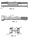
- the permanent magnet shaft 28 is shown in an enlarged section in Figure 2.
- the power head end 24 of the permanent magnet sleeve 16 may have a slightly smaller outer diameter than the outer diameter of the remainder of the permanent magnet sleeve 16.
- the permanent magnet sleeve 16 can be constructed of a non-magnetic material such as Inconel 718, while the permanent magnet 17, disposed within the permanent magnet sleeve 16, may be constructed of a permanent magnet material such as samarium cobalt, neodymium-iron-boron or similar materials.
- cylindrical brass plugs (not shown) may be included at either end of the permanent magnet 17.
- the tie bolt shaft 34 is illustrated in Figure 3 and generally comprises a tie bolt 43 having a cup shaped member 45 at one end thereof and a threaded portion 44 at the opposite end thereof.
- the open end of the cup shaped member 45 faces away from the tie bolt 43.
- the flexible disk shaft 40 is shown in an enlarged sectional view in Figure 4.
- the flexible disk shaft 40 includes a first flexible disk member 47 and a second flexible disk member 48 connected by a quill shaft 50.
- the first flexible disk member 47 is generally cup shaped having a flexible disk 51 and cylindrical sides 52 with the open end of the first flexible disk member 47 facing away from the quill shaft 40.
- the second flexible disk member 48 is also generally cup shaped having a flexible disk 53 and cylindrical sides 54.
- the open end of the second flexible disk member 48 also faces away from the quill shaft 40 with the power head end 55 having a slightly smaller outer diameter than the remainder of the cylindrical sides 54 of the second flexible disk member 48.
- the disk members 47, 48 may be of 17-4 PH stainless steel for good strength and fatigue properties.
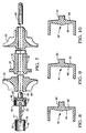
- the permanent magnet shaft 28 of Figure 2, the tie bolt shaft 34 of Figure 3, and the flexible disk shaft 40 of Figure 4 are shown assembled in Figure 5 and 6.
- the cylindrical sides 52 of the cup-shaped flexible disk member 47 of the flexible disk shaft 40 fit over the power head end 24 of the permanent magnet shaft 28 with an interference fit.
- an interference fit is meant an interference of between 0.0002 and 0.005 inches.
- the cylindrical sides 46 of the cup shaped member 45 of the tie bolt shaft 34 fit over the open end 55 of the second flexible disk member 48 of the flexible disk shaft 40, also with an interference fit.
- the power head shaft generally comprises the hub 66 of the compressor wheel 32, bearing rotor 36 including bearing rotor disk 37, and the hub 67 of the turbine wheel 33.
- Each of the hub 66 of the compressor wheel 32, bearing rotor 36 including bearing rotor thrust disk 37, and the hub 67 of the turbine wheel 33 include a central bore that fits over the tie bolt 43 of the tie bolt shaft 34.
- the compressor wheel 32, the bearing rotor 36 and the turbine wheel 33 are held in compression on the tie bolt 43 between the cup shaped member 45 and the tie bolt nut 41 on the threaded end 44 of the tie bolt 43.
- the tie bolt 43 will be stretched to some degree. This stretching of the tie bolt 43 will force the open end of the cup shaped member 45 to slightly close, that is, the cylindrical sides 46 will narrow towards the open end. This will serve to increase the interference fit between the power head end 55 of the second flexible disk member 48.
- Figures 8-10 illustrate three alternate flexible disk members for the flexible disk shaft of Figure 4.
- the thickness of the disk is increased from the cylindrical sides of the flexible disk member to the centerline of the disk.
- the disk 91 includes a flat outer surface 92 facing the quill shaft 50 and a tapered inner surface 93.
- the flexible disk 94 has a tapered outer surface 95 and a flat inner surface 96 while the flexible disk 97 of Figure 10 has both the outer surface 98 and inner surface 99 tapered.
- Thin brass disks are first bonded to each end of the unmagnetized samarium cobalt permanent magnet 17 having a cylindrical shape and having a preferred magnetic axis normal to the cylinder's axis.
- the permanent magnet assembly with brass end pieces is then ground to obtain a precise outer diameter. It is then installed by thermal assembly techniques or other conventional means into the hollow permanent magnet sleeve 16 which has an internal diameter that is slightly smaller than the permanent magnet assembly outer diameter.
- the resulting radial interference fit assures that the permanent magnet 17 will not crack due to the tensile stresses that are induced when the permanent magnet assembly and permanent magnet sleeve 16 experience rotationally induced gravitational fields when used in the turbomachine.
- the permanent magnet sleeve 16 is longer than the permanent magnet assembly such that the permanent magnet sleeve has hollow ends when the permanent magnet assembly is installed therein.
- the permanent magnet shaft assembly then has its outer surface contoured by grinding. It is then balanced as a component after which the permanent magnet 17 is magnetized.
- the resulting permanent magnet shaft is a specific example of the first stiff shaft 28 of the present invention.
- the second flexible disk 48 of the flexible disk shaft 40 is pressed with an interference fit within the generally cup shaped member 45 of the tie bolt shaft 34. Then the first flexible disk member 47 of the flexible disk shaft 40 is then pressed with an interference fit over the power head end 24 of the permanent magnet shaft 28.
- the compressor wheel 32, bearing rotor 36 and turbine wheel 33 are then mounted upon the tie bolt 43 of the tie bolt shaft 34 and held in compression by the tie bolt nut 41.
- the turbogenerator typically does not require assembly balancing. It may not even need to be checked to determine the state of rotor balance before being put into operation.
- all the rigid body criticals are negotiated when the machine has accelerated above 40,000 rpm. These negotiated criticals are typically well damped. No flexural criticals need to be negotiated as the operating speed is 96,000 rpm and the first flexural critical speed is over 200,000 rpm. This allows the operating range to be free of criticals except at the start sequence.
- the compound shaft of the present invention provides for tuning or shifting of the rotor's rigid body and flexural critical frequencies. This provides flexibility in selecting the operating speed range of the turbomachine shaft. In most cases, a wide operating range is desirable over which there should be no rigid body or flexural criticals that need to be negotiated during normal operation. This spread is achieved by lowering the rigid body critical frequencies and increasing the first flexural critical frequency. There are a number of factors which can affect frequencies of the rigid body criticals and the frequency of the first flexural critical. The length of the quill shaft between the flexible disk members and the thickness of the flexible disk, for example, can significantly affect the frequency of the first flexural critical; the shorter the quill shaft, the higher the frequency.
- the double flexure provides an additional degree of freedom by allowing shear decoupling of the two stiff shafts.
- the decoupled system is less sensitive to shaft misalignment and imbalance.
- the operating speed range is free of rotor criticals. Torque and axial loads are transmitted while allowing for misalignment.
Landscapes
- Engineering & Computer Science (AREA)
- Mechanical Engineering (AREA)
- General Engineering & Computer Science (AREA)
- Structures Of Non-Positive Displacement Pumps (AREA)
- Turbine Rotor Nozzle Sealing (AREA)
- Supercharger (AREA)
- Flexible Shafts (AREA)
Abstract
Description
Claims (21)
- A compound shaft comprising:a first stiff shaft;a flexible disk shaft having a pair of flexible disks and a quill shaft disposed between and connecting said pair of flexible disks;a tie bolt shaft having a generally cup shaped member at one end thereof; anda second stiff shaft removably mounted upon said tie bolt shaft,one of said pair of flexible disks of said flexible disk shaft interference fit with said first stiff shaft and the other of said pair of flexible disks of said flexible disk shaft interference fit with said generally cup shaped member of said tie bolt shaft.
- A compound shaft comprising:a first stiff shaft having a hollow sleeve at one end thereof;a tie bolt shaft having a generally cup shaped member at one end thereof;a second stiff shaft removably mounted upon said tie bolt shaft; anda flexible disk shaft having a pair of flexible disks and a quill shaft disposed between and connecting said pair of flexible disks,one of said pair of flexible disks of said flexible disk shaft interference fit over the hollow sleeve of said first stiff shaft and the other of said pair of flexible disks of said flexible disk shaft interference fit into said generally cup shaped member of said tie bolt shaft.
- The compound shaft of claim 2 wherein said pair of flexible disks of said flexible disk shaft are generally cup shaped.
- The compound shaft of claim 2 wherein the thickness of each of said pair of flexible disks of said flexible disk shaft generally decreases radially outward.
- The compound shaft of claim 4 wherein the radial extending surface of each of said pair of flexible disks of said flexible disk shaft facing said quill shaft is radially flat and the radial extending surface of each of said flexible disks of said flexible disk shaft facing away from said quill shaft is radially tapered to produce the generally radially outwardly decreasing thickness of each of said flexible disks.
- The compound shaft of claim 4 wherein the radial extending surface of each of said pair of flexible disks of said flexible disk shaft facing away from said quill shaft is radially flat and the radial extending surface of each of said flexible disks of said flexible disk shaft facing said quill shaft is radially tapered to produce the generally radially outwardly decreasing thickness of each of said flexible disks.
- The compound shaft of claim 4 wherein the radial extending surface of each of said pair of flexible disks of said flexible disk shaft facing said quill shaft is radially tapered and the radial extending surface of each of said flexible disks of said flexible disk shaft facing away from said quill shaft is radially tapered to produce the generally radially outwardly decreasing thickness of each of said flexible disks.
- The compound shaft of claim 2 wherein the thickness of each of said pair of flexible disks of said flexible disk shaft is generally radially uniform.
- The compound shaft of claim 2 wherein said compound shaft is for a permanent magnet turbogenerator and said first stiff shaft is a cylindrical sleeve enclosing a permanent magnet of said permanent magnet turbogenerator and said second stiff shaft is a power head shaft of said turbogenerator mounted in compression on said tie bolt shaft.
- A compound shaft for a permanent magnet turbogenerator, said compound shaft comprising:a flexible disk shaft having a pair of flexible disks and a quill shaft disposed between and connecting said pair of flexible disks; anda tie bolt shaft having a tie bolt with a generally cup shaped member at one end thereof and a threaded nut at the other end thereof;said permanent magnet turbogenerator having a permanent magnet shaft including a permanent magnet disposed within a permanent magnet sleeve rotatably supported by a pair of spaced journal bearings within a permanent magnet stator, and a power head including a compressor wheel, a bearing rotor, and a turbine wheel rotatably supported by a single journal bearing and a bi-directional thrust bearing within a compressor and turbine housing, said power head removably mounted in compression on said tie bolt between said generally cup shaped member and said threaded nut;one of said pair of said flexible disk members of said flexible disk shaft interference fit with one end of said permanent magnet sleeve and the other of said pair of flexible disk members of said flexible disk shaft interference fit with the generally cup shaped member of said tie bolt shaft.
- The compound shaft for a permanent magnet turbogenerator of claim 10 wherein said pair of flexible disks of said flexible disk shaft are generally cup shaped.
- The compound shaft for a permanent magnet turbogenerator of claim 10 wherein the thickness of each of said pair of flexible disks of said flexible disk shaft generally decreases radially outward.
- The compound shaft for a permanent magnet turbogenerator of claim 10 wherein the radial extending surface of each of said pair of flexible disks of said flexible disk shaft facing said quill shaft is radially flat and the radial extending surface of each of said flexible disks of said flexible disk shaft facing away from said quill shaft is radially tapered to produce the generally radially outwardly decreasing thickness of each of said flexible disks.
- The compound shaft for a permanent magnet turbogenerator of claim 10 wherein the radial extending surface of each of said pair of flexible disks of said flexible disk shaft facing away from said quill shaft is radially flat and the radial extending surface of each of said flexible disks of said flexible disk shaft facing said quill shaft is radially tapered to produce the generally radially outwardly decreasing thickness of each of said flexible disks.
- The compound shaft for a permanent magnet turbogenerator of claim 10 wherein the radial extending surface of each of said pair of flexible disks of said flexible disk shaft facing said quill shaft is radially tapered and the radial extending surface of each of said flexible disks of said flexible disk shaft facing away from said quill shaft is radially tapered to produce the generally radially outwardly decreasing thickness of each of said flexible disks.
- The compound shaft for a permanent magnet turbogenerator of claim 10 wherein the thickness of each of said pair of flexible disks of said flexible disk shaft is generally radially uniform.
- The compound shaft for a permanent magnet turbogenerator of claim 10 wherein one of said pair of said flexible disk members of said flexible disk shaft interference fit over one end of said permanent magnet sleeve and the other of said pair of flexible disk members of said flexible disk shaft interference fit into the generally cup shaped member of said tie bolt shaft.
- The compound shaft for a permanent magnet turbogenerator of claim 10 wherein said journal bearings are compliant foil hydrodynamic fluid film journal bearings.
- The compound shaft for a permanent magnet turbogenerator of claim 10 wherein said bi-directional thrust bearing is a compliant foil hydrodynamic fluid film thrust bearing.
- The compound shaft for a permanent magnet turbogenerator of claim 10 wherein said journal bearings are compliant foil hydrodynamic fluid film journal bearings and said bi-directional thrust bearing is a compliant foil hydrodynamic fluid film thrust bearing.
- A method of coupling a first stiff shaft with a second stiff shaft comprising the steps of:providing a tie bolt shaft having a generally cup shaped member at one end thereof and a threaded nut at the other end thereof;providing a flexible disk shaft between said first stiff shaft and said tie bolt shaft, said flexible stiff shaft having a pair of flexible disks and a quill shaft disposed between and connecting said pair of flexible disks,interference fitting one of said pair of flexible disks of said flexible disk shaft with said first stiff shaft;interference fitting the other of said pair of flexible disks of said flexible disk shaft within the cup shaped member of said tie bolt shaft, andcompressively mounting the second stiff shaft on said tie bolt shaft between said generally cup shaped member and said threaded nut to stretch said tie bolt and increase the interference fit between the other of said pair of flexible disks of said flexible disk shaft and the cup shaped member of said tie bolt shaft.
Applications Claiming Priority (2)
| Application Number | Priority Date | Filing Date | Title |
|---|---|---|---|
| US934430 | 1992-08-24 | ||
| US08/934,430 US5964663A (en) | 1997-09-19 | 1997-09-19 | Double diaphragm compound shaft |
Publications (3)
| Publication Number | Publication Date |
|---|---|
| EP0903466A2 true EP0903466A2 (en) | 1999-03-24 |
| EP0903466A3 EP0903466A3 (en) | 2000-07-19 |
| EP0903466B1 EP0903466B1 (en) | 2004-06-30 |
Family
ID=25465564
Family Applications (1)
| Application Number | Title | Priority Date | Filing Date |
|---|---|---|---|
| EP98307606A Expired - Lifetime EP0903466B1 (en) | 1997-09-19 | 1998-09-18 | Double diaphragm compound shaft |
Country Status (6)
| Country | Link |
|---|---|
| US (3) | US5964663A (en) |
| EP (1) | EP0903466B1 (en) |
| JP (1) | JPH11159520A (en) |
| CA (1) | CA2242947C (en) |
| DE (1) | DE69824801T2 (en) |
| IL (1) | IL125679A (en) |
Families Citing this family (29)
| Publication number | Priority date | Publication date | Assignee | Title |
|---|---|---|---|---|
| TW390936B (en) | 1997-12-20 | 2000-05-21 | Allied Signal Inc | Microturbine power generating system |
| US20020079760A1 (en) * | 2000-10-31 | 2002-06-27 | Capstone Turbine Corporation | Double diaphragm coumpound shaft |
| US6539720B2 (en) | 2000-11-06 | 2003-04-01 | Capstone Turbine Corporation | Generated system bottoming cycle |
| US6571563B2 (en) | 2000-12-19 | 2003-06-03 | Honeywell Power Systems, Inc. | Gas turbine engine with offset shroud |
| JP2004521267A (en) * | 2001-07-06 | 2004-07-15 | ボーグワーナー・インコーポレーテッド | Compressor driven by electric motor |
| GB0213166D0 (en) * | 2002-06-10 | 2002-07-17 | Leuven K U Res & Dev | Monolithic cutting tool |
| JP4112468B2 (en) * | 2003-10-02 | 2008-07-02 | 本田技研工業株式会社 | Axis of rotation |
| US7112036B2 (en) * | 2003-10-28 | 2006-09-26 | Capstone Turbine Corporation | Rotor and bearing system for a turbomachine |
| US7251942B2 (en) * | 2004-06-29 | 2007-08-07 | Honeywell International Inc. | Integrated gearless and nonlubricated auxiliary power unit |
| KR101025773B1 (en) * | 2004-07-30 | 2011-04-04 | 삼성테크윈 주식회사 | Turbogenerator Apparatus and Fuel Cell System Equipped with the Turbogenerator Apparatus |
| US20090211260A1 (en) * | 2007-05-03 | 2009-08-27 | Brayton Energy, Llc | Multi-Spool Intercooled Recuperated Gas Turbine |
| CA2762184A1 (en) | 2009-05-12 | 2010-11-18 | Icr Turbine Engine Corporation | Gas turbine energy storage and conversion system |
| US8376690B2 (en) * | 2009-12-08 | 2013-02-19 | Honeywell International Inc. | Three bearing flexible shaft for high speed turbomachinery |
| US8866334B2 (en) | 2010-03-02 | 2014-10-21 | Icr Turbine Engine Corporation | Dispatchable power from a renewable energy facility |
| US8814499B2 (en) * | 2010-04-19 | 2014-08-26 | Korea Fluid Machinery Co., Ltd. | Centrifugal compressor |
| US8984895B2 (en) | 2010-07-09 | 2015-03-24 | Icr Turbine Engine Corporation | Metallic ceramic spool for a gas turbine engine |
| AU2011295668A1 (en) | 2010-09-03 | 2013-05-02 | Icr Turbine Engine Corporation | Gas turbine engine configurations |
| US9051873B2 (en) | 2011-05-20 | 2015-06-09 | Icr Turbine Engine Corporation | Ceramic-to-metal turbine shaft attachment |
| NL2009734C2 (en) | 2012-06-29 | 2013-12-31 | Micro Turbine Technology B V | A combination of two interconnected shafts for high-speed rotors. |
| US10094288B2 (en) | 2012-07-24 | 2018-10-09 | Icr Turbine Engine Corporation | Ceramic-to-metal turbine volute attachment for a gas turbine engine |
| KR101363974B1 (en) * | 2012-11-22 | 2014-02-18 | 한국과학기술연구원 | Micro gas turbine having compact structure |
| US10704607B2 (en) | 2016-08-22 | 2020-07-07 | Goodrich Corporation | Flexible coupling arrangements for drive systems |
| JP6723977B2 (en) * | 2017-12-13 | 2020-07-15 | 三菱重工マリンマシナリ株式会社 | Supercharger |
| IT201900016145A1 (en) | 2019-09-12 | 2021-03-12 | Ge Avio Srl | SHOCK ABSORBER OF AN AXIAL HYPERSTATIC SYSTEM |
| JP7353990B2 (en) * | 2020-01-10 | 2023-10-02 | 東芝エネルギーシステムズ株式会社 | gas turbine power generation system |
| WO2021144002A1 (en) * | 2020-01-13 | 2021-07-22 | Bladon Jets Holdings Limited | Monolithic rotor and compressor wheel |
| JP7518793B2 (en) * | 2021-03-31 | 2024-07-18 | 本田技研工業株式会社 | Combined Power System |
| US11979062B2 (en) * | 2021-12-22 | 2024-05-07 | Garrett Transportation I Inc | Rotor assembly for turbomachine having electric motor with solitary solid core permanent magnet |
| DE102024121802B3 (en) * | 2024-07-31 | 2025-05-28 | pyropower GmbH | Coupling device |
Family Cites Families (40)
| Publication number | Priority date | Publication date | Assignee | Title |
|---|---|---|---|---|
| US1283787A (en) * | 1916-06-17 | 1918-11-05 | Gustavus A Schanze | Flexible shaft and universal coupling therefor. |
| US1460212A (en) * | 1921-04-01 | 1923-06-26 | Olive Paul | Universal joint |
| US1795765A (en) * | 1929-06-29 | 1931-03-10 | Dickerson Malcolm | Universal joint |
| US1913198A (en) * | 1932-07-16 | 1933-06-06 | Inland Mfg Co | Universal joint |
| US2300689A (en) * | 1941-03-24 | 1942-11-03 | American Brake Shoe & Foundry | Automatic priming pump and the like |
| US2483616A (en) * | 1947-05-22 | 1949-10-04 | Svenska Flygmotor Aktiebolaget | Rotor for multistage turbines or similar machines |
| US2625883A (en) * | 1951-01-25 | 1953-01-20 | Julia M Howser | Centrifugal pump drive and seal means |
| US2848882A (en) * | 1955-11-25 | 1958-08-26 | Gen Motors Corp | Drive noise insulating means |
| GB867838A (en) * | 1956-09-06 | 1961-05-10 | Westinghouse Brake & Signal | Method of manufacturing hermetically sealed containers for crystal rectifiers |
| US3299722A (en) * | 1964-10-08 | 1967-01-24 | Jr Albert G Bodine | Mechanical sonic vibration generator with frequency step-up characteristic |
| US3448591A (en) * | 1967-12-13 | 1969-06-10 | Rudolf A Spyra | Spiral disk drive coupling |
| US3500754A (en) * | 1968-01-25 | 1970-03-17 | Loewe Pumpenfabrik Gmbh | Centrifugal pump units |
| US3635050A (en) * | 1969-11-25 | 1972-01-18 | Woodward Governor Co | Drive transmission with universal couplings |
| US3788099A (en) * | 1971-06-30 | 1974-01-29 | D Miller | Flexible coupling |
| US3779451A (en) * | 1971-11-22 | 1973-12-18 | Int Equipment Co | Flexible shaft stabilizer |
| SE414137B (en) * | 1972-01-12 | 1980-07-14 | Stihl Maschf Andreas | CLUTCH DEVICE FOR ADDITIVES, SEPARATE ADDITIVES FOR ENGINE CHAIN SAW |
| US3855817A (en) * | 1972-04-19 | 1974-12-24 | Gates Rubber Co | Flexible shaft |
| CH584365A5 (en) * | 1972-10-25 | 1977-01-31 | Elfit Sa | |
| US4176519A (en) * | 1973-05-22 | 1979-12-04 | United Turbine Ab & Co., Kommanditbolag | Gas turbine having a ceramic rotor |
| US3973867A (en) * | 1975-04-09 | 1976-08-10 | Chien Fu Lee | Radial flow type pump |
| DE2527498A1 (en) * | 1975-06-20 | 1976-12-30 | Daimler Benz Ag | RADIAL TURBINE WHEEL FOR A GAS TURBINE |
| DE2529458C2 (en) * | 1975-07-02 | 1982-11-18 | Sihi Gmbh & Co Kg, 2210 Itzehoe | Centrifugal pump unit |
| US4044628A (en) * | 1976-03-24 | 1977-08-30 | U.S. Manufacturing Corporation | Torsional damper |
| US4121532A (en) * | 1977-01-06 | 1978-10-24 | Coryell Iii William Harlan | Speedboat safety driveline coupling |
| US4225114A (en) * | 1978-10-19 | 1980-09-30 | General Signal Corporation | Butterfly valve with improved shaft connection |
| US4265099A (en) * | 1979-03-02 | 1981-05-05 | General Electric Company | Flexible coupling |
| DE3021318C2 (en) * | 1980-06-06 | 1982-04-22 | Klein, Schanzlin & Becker Ag, 6710 Frankenthal | Shaft connection |
| US4411634A (en) * | 1980-11-10 | 1983-10-25 | The Bendix Corporation | Flexible coupling having molded plastic flexible diaphragms |
| JPS57171122A (en) * | 1981-04-14 | 1982-10-21 | Toshiba Corp | Structure for mounting rotary disc on rotary shaft |
| US4560364A (en) * | 1981-11-09 | 1985-12-24 | Hughes Helicopters, Inc. | Fail-safe improvement for a flexible shaft coupling |
| US4786238A (en) * | 1984-12-20 | 1988-11-22 | Allied-Signal Inc. | Thermal isolation system for turbochargers and like machines |
| JPH037367Y2 (en) * | 1985-05-31 | 1991-02-25 | ||
| EP0211090B1 (en) * | 1985-07-26 | 1989-08-23 | BHS-Bayerische Berg-, Hütten- und Salzwerke Aktiengesellschaft | Manufacturing process for a flexible coupling means for the transmission of torque |
| US4795012A (en) * | 1987-05-26 | 1989-01-03 | Borg-Warner Automotive, Inc. | Spiral spring disc torsional coupling |
| US5020932A (en) * | 1988-12-06 | 1991-06-04 | Allied-Signal Inc. | High temperature ceramic/metal joint structure |
| US4934138A (en) * | 1988-12-06 | 1990-06-19 | Allied-Signal Inc. | High temperature turbine engine structure |
| DE3907855A1 (en) * | 1989-03-10 | 1990-09-13 | Bhs Bayerische Berg | BENDING ELASTIC CLUTCH ELEMENT AND METHOD FOR PRODUCING THE SAME |
| US5158504A (en) * | 1989-05-12 | 1992-10-27 | Lucas Aerospace Power Transmission Corp. | Flexible coupling including a flexible diaphragm element contoured with its thinnest thickness near the center thereof |
| US5577963A (en) * | 1994-05-02 | 1996-11-26 | Eaton Corporation | Torsion isolator spring with pivotal ends |
| US5697848A (en) * | 1995-05-12 | 1997-12-16 | Capstone Turbine Corporation | Compound shaft with flexible disk coupling |
-
1997
- 1997-09-19 US US08/934,430 patent/US5964663A/en not_active Expired - Lifetime
-
1998
- 1998-07-06 CA CA002242947A patent/CA2242947C/en not_active Expired - Lifetime
- 1998-08-06 IL IL12567998A patent/IL125679A/en not_active IP Right Cessation
- 1998-09-16 JP JP10261104A patent/JPH11159520A/en not_active Withdrawn
- 1998-09-18 EP EP98307606A patent/EP0903466B1/en not_active Expired - Lifetime
- 1998-09-18 DE DE69824801T patent/DE69824801T2/en not_active Expired - Lifetime
- 1998-12-30 US US09/224,208 patent/US6037687A/en not_active Expired - Lifetime
- 1998-12-30 US US09/224,206 patent/US6094799A/en not_active Expired - Lifetime
Also Published As
| Publication number | Publication date |
|---|---|
| US5964663A (en) | 1999-10-12 |
| US6094799A (en) | 2000-08-01 |
| CA2242947A1 (en) | 1999-03-19 |
| EP0903466A3 (en) | 2000-07-19 |
| IL125679A0 (en) | 1999-04-11 |
| US6037687A (en) | 2000-03-14 |
| DE69824801D1 (en) | 2004-08-05 |
| IL125679A (en) | 2001-08-26 |
| DE69824801T2 (en) | 2005-07-21 |
| EP0903466B1 (en) | 2004-06-30 |
| JPH11159520A (en) | 1999-06-15 |
| CA2242947C (en) | 2007-04-24 |
Similar Documents
| Publication | Publication Date | Title |
|---|---|---|
| EP0903466B1 (en) | Double diaphragm compound shaft | |
| US5697848A (en) | Compound shaft with flexible disk coupling | |
| CA2354818C (en) | Turbocharger rotor with alignment couplings | |
| JP4112468B2 (en) | Axis of rotation | |
| KR101164576B1 (en) | Electric supercharger | |
| US5898990A (en) | Method of assembling a magnet ring on a rotor | |
| AU2004201490B2 (en) | Turbocharge rotor | |
| JP3587350B2 (en) | Turbocharger with generator / motor | |
| US20100284794A1 (en) | Low pressure turbine rotor disk | |
| JPS6142510B2 (en) | ||
| JP4447866B2 (en) | Exhaust turbine turbocharger | |
| JPS6035939A (en) | Rotor and its manufacturing method | |
| EP0240514A4 (en) | Permanent magnet rotor assembly with fibrous wrap. | |
| US7010917B2 (en) | Compressor wheel assembly | |
| JP4413553B2 (en) | Exhaust turbine turbocharger | |
| EP3523506B1 (en) | Method of assembling an electrified turbocharger | |
| JP2000145469A (en) | Method of assembling turbocharger with generator / motor | |
| US12421869B2 (en) | Torsional vibration damper mechanism for gas turbine engine | |
| CN113423930A (en) | Bearing structure, supercharger provided with same, and method for assembling supercharger | |
| US20180106263A1 (en) | Single piece bearing housing with turbine end plate | |
| JPH08226302A (en) | Fixing mechanism of impeller of centrifugal compressor or centrifugal turbine | |
| KR20240042420A (en) | Rotor for high-speed electrical machines | |
| CN115912718A (en) | Rotor assembly and magnetic levitation motor | |
| JPH06100083B2 (en) | Fixing mechanism of impeller of centrifugal compressor or centrifugal turbine | |
| JP2022523111A (en) | A device for compressing a fluid driven by an electromechanical machine with a compression shaft that runs through a rotor. |
Legal Events
| Date | Code | Title | Description |
|---|---|---|---|
| PUAI | Public reference made under article 153(3) epc to a published international application that has entered the european phase |
Free format text: ORIGINAL CODE: 0009012 |
|
| AK | Designated contracting states |
Kind code of ref document: A2 Designated state(s): DE FR GB |
|
| AX | Request for extension of the european patent |
Free format text: AL;LT;LV;MK;RO;SI |
|
| PUAL | Search report despatched |
Free format text: ORIGINAL CODE: 0009013 |
|
| AK | Designated contracting states |
Kind code of ref document: A3 Designated state(s): AT BE CH CY DE DK ES FI FR GB GR IE IT LI LU MC NL PT SE |
|
| AX | Request for extension of the european patent |
Free format text: AL;LT;LV;MK;RO;SI |
|
| RIC1 | Information provided on ipc code assigned before grant |
Free format text: 7F 01D 5/02 A, 7F 01D 15/10 B, 7F 01D 25/04 B, 7F 16D 3/77 B, 7F 16D 3/72 B, 7H 02K 7/16 B, 7H 02K 7/08 B |
|
| 17P | Request for examination filed |
Effective date: 20010109 |
|
| AKX | Designation fees paid |
Free format text: DE FR GB |
|
| 17Q | First examination report despatched |
Effective date: 20020906 |
|
| GRAH | Despatch of communication of intention to grant a patent |
Free format text: ORIGINAL CODE: EPIDOS IGRA |
|
| GRAS | Grant fee paid |
Free format text: ORIGINAL CODE: EPIDOSNIGR3 |
|
| GRAA | (expected) grant |
Free format text: ORIGINAL CODE: 0009210 |
|
| AK | Designated contracting states |
Kind code of ref document: B1 Designated state(s): DE FR GB |
|
| REG | Reference to a national code |
Ref country code: GB Ref legal event code: FG4D |
|
| REF | Corresponds to: |
Ref document number: 69824801 Country of ref document: DE Date of ref document: 20040805 Kind code of ref document: P |
|
| ET | Fr: translation filed | ||
| PLBE | No opposition filed within time limit |
Free format text: ORIGINAL CODE: 0009261 |
|
| STAA | Information on the status of an ep patent application or granted ep patent |
Free format text: STATUS: NO OPPOSITION FILED WITHIN TIME LIMIT |
|
| 26N | No opposition filed |
Effective date: 20050331 |
|
| REG | Reference to a national code |
Ref country code: FR Ref legal event code: PLFP Year of fee payment: 19 |
|
| REG | Reference to a national code |
Ref country code: FR Ref legal event code: PLFP Year of fee payment: 20 |
|
| PGFP | Annual fee paid to national office [announced via postgrant information from national office to epo] |
Ref country code: FR Payment date: 20170810 Year of fee payment: 20 Ref country code: DE Payment date: 20170912 Year of fee payment: 20 Ref country code: GB Payment date: 20170913 Year of fee payment: 20 |
|
| REG | Reference to a national code |
Ref country code: DE Ref legal event code: R071 Ref document number: 69824801 Country of ref document: DE |
|
| REG | Reference to a national code |
Ref country code: GB Ref legal event code: PE20 Expiry date: 20180917 |
|
| PG25 | Lapsed in a contracting state [announced via postgrant information from national office to epo] |
Ref country code: GB Free format text: LAPSE BECAUSE OF EXPIRATION OF PROTECTION Effective date: 20180917 |