EP0903306A1 - Container, particularly refuse container, provided with compacting means - Google Patents
Container, particularly refuse container, provided with compacting means Download PDFInfo
- Publication number
- EP0903306A1 EP0903306A1 EP98203181A EP98203181A EP0903306A1 EP 0903306 A1 EP0903306 A1 EP 0903306A1 EP 98203181 A EP98203181 A EP 98203181A EP 98203181 A EP98203181 A EP 98203181A EP 0903306 A1 EP0903306 A1 EP 0903306A1
- Authority
- EP
- European Patent Office
- Prior art keywords
- container
- partition
- refuse
- funnel
- ram
- Prior art date
- Legal status (The legal status is an assumption and is not a legal conclusion. Google has not performed a legal analysis and makes no representation as to the accuracy of the status listed.)
- Withdrawn
Links
Images
Classifications
-
- B—PERFORMING OPERATIONS; TRANSPORTING
- B65—CONVEYING; PACKING; STORING; HANDLING THIN OR FILAMENTARY MATERIAL
- B65F—GATHERING OR REMOVAL OF DOMESTIC OR LIKE REFUSE
- B65F3/00—Vehicles particularly adapted for collecting refuse
- B65F3/14—Vehicles particularly adapted for collecting refuse with devices for charging, distributing or compressing refuse in the interior of the tank of a refuse vehicle
- B65F3/20—Vehicles particularly adapted for collecting refuse with devices for charging, distributing or compressing refuse in the interior of the tank of a refuse vehicle with charging pistons, plates, or the like
- B65F3/201—Vehicles particularly adapted for collecting refuse with devices for charging, distributing or compressing refuse in the interior of the tank of a refuse vehicle with charging pistons, plates, or the like the charging pistons, plates or the like moving rectilinearly
-
- B—PERFORMING OPERATIONS; TRANSPORTING
- B65—CONVEYING; PACKING; STORING; HANDLING THIN OR FILAMENTARY MATERIAL
- B65F—GATHERING OR REMOVAL OF DOMESTIC OR LIKE REFUSE
- B65F3/00—Vehicles particularly adapted for collecting refuse
- B65F3/24—Vehicles particularly adapted for collecting refuse with devices for unloading the tank of a refuse vehicle
- B65F3/26—Vehicles particularly adapted for collecting refuse with devices for unloading the tank of a refuse vehicle by tipping the tank
Definitions
- the invention concerns a container, particularly refuse container, provided with compacting means to compact material, particularly refuse, said container comprises a storage room, a press room and an entry and comprising a housing and also a funnel being present below the entry and debouch into the press room, said funnel comprises a partition which is present between the entry and the storage room.
- Such a container is generally known and is often used by refuse lorries to collect household refuse and other refuse.
- the refuse will be put into the container via the entry and will fall through the funnel before a ram which presses the refuse into the storage room.
- the ram moves close under the funnel whereby the lower side of said partition of the funnel acts as a breaking beam.
- material with a relatively high density, like paper, is part of the refuse it often happens that this material sticks between the upper side of the ram and the lower side of the partition of the funnel, and the ram jams between the guide, in which the ram moves, and the partition of the funnel. This obliges an early emptying and cleaning of the container.
- the emptying takes place by turning the container back to front about a vertical axle and then tipping the container while opening the back wall of the container. It has been appeared that after emptying some refuse remains in the funnel and thus the container is not complete emptied and can pick up less refuse the next time. Moreover it has appeared that the filling of the storage room is not optimum during collecting and compacting of refuse.
- the container according to the invention is characterised in that the partition is hinged with its upper side to the housing of the container.
- the partition is freely rotatable about a hinge axle. Because the partition is freely rotatable, refuse can not stick between the lower side of the partition and the upper side of the ram during the compacting movement.
- the partition turns under the action of its own weigth and releases the room inside the funnel so that no refuse can remain in the funnel. Beside this it has been appeared that by being rotatable of the partition a better filling of the storage room will be obtained because the refuse can get easier in the part of the storage room behind the partition.
- An embodiment of the container according to the invention is characterised in that the container comprises at least one stop, the partition being present against this stop when the container is in its horizontal position.
- a further embodiment of the container is characterised in that the partition is heavy constructed and acts as a breaking beam to break the sticked material from each other.
- the compacting means comprise a movable ram, which comprises a compacting plate at its front end hinged at the remaining part of the ram. It has been appeared, namely, that behind the compacting plate of the ram refuse accumulates which gets under and along the compacting plate during compacting. In case there is too much refuse behind the compacting plate of the ram, the ram can not be pulled back enough and the funnel will be partly closed which obliges a premature emptying and cleaning of the container.
- the compacting plate By hinging the compacting plate to the ram, the compacting plate turns to the open position during tipping of the container when emptying the container, so that the refuse accumulated behind the compacting plate will fall out of the room behind the compacting plate and it is prevented that too much refuse will accumulate behind the compacting plate.
- the compacting plate is freely rotatable about a hinge axle.
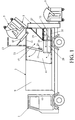
- FIG. 1 shows a refuse lorry 1 with a container 3 of the invention.
- the refuse lorry 1 has an apparatus 5 (shown schematically) for lifting and emptying of refuse boxes 7 into the container 3.
- the container 3 has a housing 9 comprising an entry 11 which can be closed by a ramp 13.
- the ramp 13 can be opened and closed by means of a cylinder 15 which is hinged to the ramp 13 and the housing 9.
- a funnel 17 is present below the entry 11.
- the funnel 17 has a fixed wall 19, which is fixed to the housing 9 of the container, and a partition 21 which also acts as a breaking beam to break the refuse during compacting.
- the partition 21 is hinged at the housing 9 and is freely rotatable about a hinge axle 23.
- the partition 21 rests with both sides against stops 25 which are present at the inner sides of the side walls of the housing 9.
- the compacting means 27 comprise a ram 31 which can be pushed by a cylinder 33.
- the cylinder 33 is hinged at the housing 9 and at a frame of the ram 31.
- the ram 31 has a closing plate 35 at the upper side and a compacting plate 37 at the front side.
- the compacting plate 37 is hinged at the remaining part of the ram and can rotate freely about a hinge axle 39.
- the compacting plate 37 can only rotate in the direction of the arrow indicated with a dotted line.
- the compacting plate is retained by a stop on the ram.
- the ram 31 presses the refuse into a storage room 41, present in the container, and slips via a guide (not shown) under the funnel to the position indicated with dotted lines.
- the ram 31 moves close under the partition 21, which breakes the sticked refuse by this movement.
- the fact that the partition 21 is hinged prevents the refuse from getting sticked between the lower side of the partition 21 and the closing plate 35 of the ram 31. With this also the refuse can get better behind the partition 21 into the storage room 41 so that a better filling of the storage room is obtained.
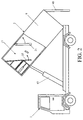
- FIG 2 a refuse lorry 1 with a container 3 is shown during emptying of the container.
- the container 3 Before tipping the container, the container 3 is turned over 180 degrees about a vertical axle in the middle of the container, so that the container 3 is placed back to front on the refuse lorry 1.
- the container 3 After a back wall 43 of the housing 9 of the container is unlocked, the container 3 will be tipped by a hydraulic cylinder 45 present on the refuse lorry 1.
- the partition 21 and the compacting plate 37 swing into their open positions and the refuse can fall out of the funnel 17 and out of the room behind the compacting plate 37. In the tipped position the container 3 can be easily cleaned from the back side by a jet of water which cleans the rooms in the funnel 17 and behind the compacting plate 37.
- pushing means for example a pushing spring
- the partition will not be rotatable freely but can only rotate against the pushing action of a spring.
- the partition will then be possible to disconnect the pushing spring.
Landscapes
- Engineering & Computer Science (AREA)
- Mechanical Engineering (AREA)
- Refuse Collection And Transfer (AREA)
- Refuse-Collection Vehicles (AREA)
Abstract
Description
- The invention concerns a container, particularly refuse container, provided with compacting means to compact material, particularly refuse, said container comprises a storage room, a press room and an entry and comprising a housing and also a funnel being present below the entry and debouch into the press room, said funnel comprises a partition which is present between the entry and the storage room.
- Such a container is generally known and is often used by refuse lorries to collect household refuse and other refuse. The refuse will be put into the container via the entry and will fall through the funnel before a ram which presses the refuse into the storage room. The ram moves close under the funnel whereby the lower side of said partition of the funnel acts as a breaking beam. In case material with a relatively high density, like paper, is part of the refuse it often happens that this material sticks between the upper side of the ram and the lower side of the partition of the funnel, and the ram jams between the guide, in which the ram moves, and the partition of the funnel. This obliges an early emptying and cleaning of the container.
- The emptying takes place by turning the container back to front about a vertical axle and then tipping the container while opening the back wall of the container. It has been appeared that after emptying some refuse remains in the funnel and thus the container is not complete emptied and can pick up less refuse the next time. Moreover it has appeared that the filling of the storage room is not optimum during collecting and compacting of refuse.
- An objective of the invention is the provision of a container as described at the beginning, whereby the problem of sticking of the compacting means is solved and the emptying and cleaning of the container will be better and easier and whereby the a better filling can be obtained than by the known containers. To this end the container according to the invention is characterised in that the partition is hinged with its upper side to the housing of the container. Preferably, the partition is freely rotatable about a hinge axle. Because the partition is freely rotatable, refuse can not stick between the lower side of the partition and the upper side of the ram during the compacting movement. During the emptying of the container, the partition turns under the action of its own weigth and releases the room inside the funnel so that no refuse can remain in the funnel. Beside this it has been appeared that by being rotatable of the partition a better filling of the storage room will be obtained because the refuse can get easier in the part of the storage room behind the partition.
- An embodiment of the container according to the invention is characterised in that the container comprises at least one stop, the partition being present against this stop when the container is in its horizontal position.
- A further embodiment of the container is characterised in that the partition is heavy constructed and acts as a breaking beam to break the sticked material from each other.
- Still a further embodiment of the container according to the invention is characterised in that the compacting means comprise a movable ram, which comprises a compacting plate at its front end hinged at the remaining part of the ram. It has been appeared, namely, that behind the compacting plate of the ram refuse accumulates which gets under and along the compacting plate during compacting. In case there is too much refuse behind the compacting plate of the ram, the ram can not be pulled back enough and the funnel will be partly closed which obliges a premature emptying and cleaning of the container. By hinging the compacting plate to the ram, the compacting plate turns to the open position during tipping of the container when emptying the container, so that the refuse accumulated behind the compacting plate will fall out of the room behind the compacting plate and it is prevented that too much refuse will accumulate behind the compacting plate. Preferably, the compacting plate is freely rotatable about a hinge axle.
- The invention will be further explained below with the aid of drawings showing a construction example of the container according to the invention. These indicate:
- Figure 1 is a partly exploded side view of a refuse lorry with an embodiment of the container according to the invention; and
- Figure 2 is the refuse lorry during emptying of the container.
-
- Figure 1 shows a
refuse lorry 1 with a container 3 of the invention. Therefuse lorry 1 has an apparatus 5 (shown schematically) for lifting and emptying of refuse boxes 7 into the container 3. The container 3 has ahousing 9 comprising anentry 11 which can be closed by aramp 13. Theramp 13 can be opened and closed by means of acylinder 15 which is hinged to theramp 13 and thehousing 9. Afunnel 17 is present below theentry 11. Thefunnel 17 has afixed wall 19, which is fixed to thehousing 9 of the container, and apartition 21 which also acts as a breaking beam to break the refuse during compacting. Thepartition 21 is hinged at thehousing 9 and is freely rotatable about ahinge axle 23. Thepartition 21 rests with both sides againststops 25 which are present at the inner sides of the side walls of thehousing 9. Below thefunnel 17 there are compacting means 27 to compact the refuse. The refuse falls via the funnel into apress room 29. The compacting means 27 comprise aram 31 which can be pushed by acylinder 33. Thecylinder 33 is hinged at thehousing 9 and at a frame of theram 31. Theram 31 has aclosing plate 35 at the upper side and acompacting plate 37 at the front side. The compactingplate 37 is hinged at the remaining part of the ram and can rotate freely about ahinge axle 39. The compactingplate 37 can only rotate in the direction of the arrow indicated with a dotted line. In the opposite direction the compacting plate is retained by a stop on the ram. Theram 31 presses the refuse into astorage room 41, present in the container, and slips via a guide (not shown) under the funnel to the position indicated with dotted lines. During this movement theram 31 moves close under thepartition 21, which breakes the sticked refuse by this movement. The fact that thepartition 21 is hinged prevents the refuse from getting sticked between the lower side of thepartition 21 and theclosing plate 35 of theram 31. With this also the refuse can get better behind thepartition 21 into thestorage room 41 so that a better filling of the storage room is obtained. - In figure 2 a
refuse lorry 1 with a container 3 is shown during emptying of the container. Before tipping the container, the container 3 is turned over 180 degrees about a vertical axle in the middle of the container, so that the container 3 is placed back to front on therefuse lorry 1. After aback wall 43 of thehousing 9 of the container is unlocked, the container 3 will be tipped by ahydraulic cylinder 45 present on therefuse lorry 1. During tipping thepartition 21 and thecompacting plate 37 swing into their open positions and the refuse can fall out of thefunnel 17 and out of the room behind the compactingplate 37. In the tipped position the container 3 can be easily cleaned from the back side by a jet of water which cleans the rooms in thefunnel 17 and behind thecompacting plate 37. - Although the above describes the invention using the drawings, it should be pointed out that the invention is in no way limited to the constructional form indicated on the drawings. The invention is open to different constructional forms, within the framework of the defined conclusions, other than the forms of construction indicated on the drawings.
- It will be also possible to place pushing means, for example a pushing spring, between the partition and the housing so that the partition will not be rotatable freely but can only rotate against the pushing action of a spring. During emptying of the container it will then be possible to disconnect the pushing spring.
Claims (6)
- Container, particularly refuse container, provided with compacting means to compact material, particularly refuse, said container comprises a storage room, a press room and an entry and comprising a housing and also a funnel being present below the entry and debouch into the press room, said funnel comprises a partition which is present between the entry and the storage room, characterised in that the partition is hinged with its upper side to the housing of the container.
- Container as claimed in claim 1, characterised in that the partition is freely rotatable about a hinge axle.
- Container as claimed in claim 1 or 2, characterised in that the container comprises at least one stop, the partition being present against this stop when the container is in its horizontal position.
- Container as claimed in claim 1,2 or 3, characterised in that the partition is heavy constructed and acts as a breaking beam to break the sticked material from each other.
- Container volgens conclusie 1,2,3 or 4, characterised in that the compacting means comprise a movable ram, which comprises a compacting plate at its front end hinged at the remaining part of the ram.
- Container volgens conclusie 5, characterised in that the compacting plate is freely rotatable about a hinge axle.
Applications Claiming Priority (2)
| Application Number | Priority Date | Filing Date | Title |
|---|---|---|---|
| NL1007093A NL1007093C2 (en) | 1997-09-22 | 1997-09-22 | Container, in particular waste container, provided with pressing means. |
| NL1007093 | 1997-09-22 |
Publications (1)
| Publication Number | Publication Date |
|---|---|
| EP0903306A1 true EP0903306A1 (en) | 1999-03-24 |
Family
ID=19765717
Family Applications (1)
| Application Number | Title | Priority Date | Filing Date |
|---|---|---|---|
| EP98203181A Withdrawn EP0903306A1 (en) | 1997-09-22 | 1998-09-22 | Container, particularly refuse container, provided with compacting means |
Country Status (2)
| Country | Link |
|---|---|
| EP (1) | EP0903306A1 (en) |
| NL (1) | NL1007093C2 (en) |
Cited By (5)
| Publication number | Priority date | Publication date | Assignee | Title |
|---|---|---|---|---|
| EP1076017A1 (en) * | 1999-08-13 | 2001-02-14 | Faun Umwelttechnik GmbH & Co. | Loading door with flap for waste container |
| WO2014037611A1 (en) * | 2012-09-04 | 2014-03-13 | Maricap Oy | Apparatus for processing material, and waste container/separating device |
| CN104401617A (en) * | 2014-09-16 | 2015-03-11 | 陕西汽车集团温州云顶汽车有限公司 | Dustbin |
| CN108974733A (en) * | 2018-08-03 | 2018-12-11 | 安徽省欣雨环卫机械有限公司 | A kind of environmental sanitation refuse vehicle with raising loading space |
| US10435239B2 (en) * | 2013-12-20 | 2019-10-08 | Maricap Oy | Apparatus for handling material, and waste container/separating device |
Citations (4)
| Publication number | Priority date | Publication date | Assignee | Title |
|---|---|---|---|---|
| AU430550B2 (en) * | 1967-12-08 | 1972-11-30 | THOMAS BARRY RICHARDS and JUWAN CHARLES RICHARDS | Refuse vehicle |
| DE2527959A1 (en) * | 1975-06-23 | 1977-01-13 | Frank Sche Eisenwerke Ag | Refuse compacting machine with ram plate - has pivoted lock between ram plate and actuating piston rod |
| DE2708471A1 (en) * | 1977-02-26 | 1978-08-31 | Wagner Gmbh & Co Kg Eberhard | Refuse transportation container with press - has curved compacting member under feed opening, with housing protecting operating cylinder |
| US5029522A (en) * | 1990-01-24 | 1991-07-09 | Brisson David J | Compactor for recyclable waste materials |
-
1997
- 1997-09-22 NL NL1007093A patent/NL1007093C2/en not_active IP Right Cessation
-
1998
- 1998-09-22 EP EP98203181A patent/EP0903306A1/en not_active Withdrawn
Patent Citations (4)
| Publication number | Priority date | Publication date | Assignee | Title |
|---|---|---|---|---|
| AU430550B2 (en) * | 1967-12-08 | 1972-11-30 | THOMAS BARRY RICHARDS and JUWAN CHARLES RICHARDS | Refuse vehicle |
| DE2527959A1 (en) * | 1975-06-23 | 1977-01-13 | Frank Sche Eisenwerke Ag | Refuse compacting machine with ram plate - has pivoted lock between ram plate and actuating piston rod |
| DE2708471A1 (en) * | 1977-02-26 | 1978-08-31 | Wagner Gmbh & Co Kg Eberhard | Refuse transportation container with press - has curved compacting member under feed opening, with housing protecting operating cylinder |
| US5029522A (en) * | 1990-01-24 | 1991-07-09 | Brisson David J | Compactor for recyclable waste materials |
Cited By (14)
| Publication number | Priority date | Publication date | Assignee | Title |
|---|---|---|---|---|
| EP1076017A1 (en) * | 1999-08-13 | 2001-02-14 | Faun Umwelttechnik GmbH & Co. | Loading door with flap for waste container |
| KR20200022548A (en) * | 2012-09-04 | 2020-03-03 | 마리캡 오이 | Apparatus for processing material, and waste container/separating device |
| KR20150052258A (en) * | 2012-09-04 | 2015-05-13 | 마리캡 오이 | Apparatus for processing material, and waste container/separating device |
| US20150232271A1 (en) * | 2012-09-04 | 2015-08-20 | Maricap Oy | Apparatus for processing material, and waste container/separating device |
| AU2017232152B2 (en) * | 2012-09-04 | 2018-10-25 | Maricap Oy | Apparatus for processing material, and waste container/separating device |
| US10442620B2 (en) | 2012-09-04 | 2019-10-15 | Maricap Oy | Apparatus for processing material, and waste container/separating device |
| WO2014037611A1 (en) * | 2012-09-04 | 2014-03-13 | Maricap Oy | Apparatus for processing material, and waste container/separating device |
| EP2892831B1 (en) * | 2012-09-04 | 2022-03-16 | Maricap OY | Apparatus for processing material, and waste container/separating device |
| US11352206B2 (en) | 2012-09-04 | 2022-06-07 | Maricap Oy | Apparatus for processing material, and waste container/separating device |
| EP4011804B1 (en) * | 2012-09-04 | 2024-01-10 | Maricap Oy | Waste container/separating device, apparatus for processing material, and press/compactor device |
| US10435239B2 (en) * | 2013-12-20 | 2019-10-08 | Maricap Oy | Apparatus for handling material, and waste container/separating device |
| CN104401617A (en) * | 2014-09-16 | 2015-03-11 | 陕西汽车集团温州云顶汽车有限公司 | Dustbin |
| CN108974733A (en) * | 2018-08-03 | 2018-12-11 | 安徽省欣雨环卫机械有限公司 | A kind of environmental sanitation refuse vehicle with raising loading space |
| CN108974733B (en) * | 2018-08-03 | 2021-03-05 | 安徽省欣雨环卫机械有限公司 | Sanitation garbage truck with improve loading space |
Also Published As
| Publication number | Publication date |
|---|---|
| NL1007093C2 (en) | 1999-03-23 |
Similar Documents
| Publication | Publication Date | Title |
|---|---|---|
| US5884556A (en) | Trash handling device | |
| US4286515A (en) | Compacting waste basket | |
| US5517907A (en) | Refuse compactor with folding compaction plate | |
| US4913301A (en) | Refuse container | |
| US3691944A (en) | Kitchen compactor | |
| DE3537546A1 (en) | Multi-chamber waste collection vehicle | |
| US20090145309A1 (en) | Compactor with pivoting compaction plate | |
| US4424740A (en) | Compactor safety interlock mechanism | |
| US5588358A (en) | Trash handling device | |
| US3424078A (en) | Trash handling and baling system | |
| CA2273893A1 (en) | Method and apparatus for collecting recyclable materials | |
| ATE281992T1 (en) | WASTE BIN LID | |
| US6276888B1 (en) | Reception, containing and compacting system of solid wastes | |
| US3881407A (en) | Waste reduction equipment | |
| CN113060455A (en) | Full-sealed garbage truck | |
| CA2059953C (en) | Apparatus and method for storing waste materials in separate storage compartments the capacity of which can be readily varied | |
| US3754501A (en) | Automatic waste disposal apparatus | |
| EP0903306A1 (en) | Container, particularly refuse container, provided with compacting means | |
| JPS6411522B2 (en) | ||
| US4117777A (en) | Refuse container, and refuse compacting and discharging device therefor | |
| CN110902219A (en) | Front-loading garbage feeding turnover mechanism and combined environmental sanitation equipment with same | |
| DE69205784T2 (en) | Garbage compactors. | |
| DE4321784A1 (en) | Waste collection device with at least one insertion opening for disposing of domestic waste such as boxes, tins, plastic material, glassware, bottles, compost waste or the like | |
| EP0105862A1 (en) | Garbage press | |
| US3633329A (en) | Apparatus for automated refuse compacting and disposal |
Legal Events
| Date | Code | Title | Description |
|---|---|---|---|
| PUAI | Public reference made under article 153(3) epc to a published international application that has entered the european phase |
Free format text: ORIGINAL CODE: 0009012 |
|
| AK | Designated contracting states |
Kind code of ref document: A1 Designated state(s): BE DE DK ES FR NL |
|
| AX | Request for extension of the european patent |
Free format text: AL;LT;LV;MK;RO;SI |
|
| 17P | Request for examination filed |
Effective date: 19990916 |
|
| AKX | Designation fees paid |
Free format text: BE DE DK ES FR NL |
|
| GRAG | Despatch of communication of intention to grant |
Free format text: ORIGINAL CODE: EPIDOS AGRA |
|
| 17Q | First examination report despatched |
Effective date: 20011221 |
|
| GRAG | Despatch of communication of intention to grant |
Free format text: ORIGINAL CODE: EPIDOS AGRA |
|
| GRAH | Despatch of communication of intention to grant a patent |
Free format text: ORIGINAL CODE: EPIDOS IGRA |
|
| STAA | Information on the status of an ep patent application or granted ep patent |
Free format text: STATUS: THE APPLICATION HAS BEEN WITHDRAWN |
|
| 18W | Application withdrawn |
Withdrawal date: 20020603 |