EP0903213A2 - Repositioning of articles between different positions within an intermittently accessible space - Google Patents
Repositioning of articles between different positions within an intermittently accessible space Download PDFInfo
- Publication number
- EP0903213A2 EP0903213A2 EP98306394A EP98306394A EP0903213A2 EP 0903213 A2 EP0903213 A2 EP 0903213A2 EP 98306394 A EP98306394 A EP 98306394A EP 98306394 A EP98306394 A EP 98306394A EP 0903213 A2 EP0903213 A2 EP 0903213A2
- Authority
- EP
- European Patent Office
- Prior art keywords
- mold
- article
- space
- during
- period
- Prior art date
- Legal status (The legal status is an assumption and is not a legal conclusion. Google has not performed a legal analysis and makes no representation as to the accuracy of the status listed.)
- Granted
Links
Images


Classifications
-
- B—PERFORMING OPERATIONS; TRANSPORTING
- B29—WORKING OF PLASTICS; WORKING OF SUBSTANCES IN A PLASTIC STATE IN GENERAL
- B29C—SHAPING OR JOINING OF PLASTICS; SHAPING OF MATERIAL IN A PLASTIC STATE, NOT OTHERWISE PROVIDED FOR; AFTER-TREATMENT OF THE SHAPED PRODUCTS, e.g. REPAIRING
- B29C45/00—Injection moulding, i.e. forcing the required volume of moulding material through a nozzle into a closed mould; Apparatus therefor
- B29C45/17—Component parts, details or accessories; Auxiliary operations
- B29C45/40—Removing or ejecting moulded articles
- B29C45/42—Removing or ejecting moulded articles using means movable from outside the mould between mould parts, e.g. robots
-
- B—PERFORMING OPERATIONS; TRANSPORTING
- B29—WORKING OF PLASTICS; WORKING OF SUBSTANCES IN A PLASTIC STATE IN GENERAL
- B29C—SHAPING OR JOINING OF PLASTICS; SHAPING OF MATERIAL IN A PLASTIC STATE, NOT OTHERWISE PROVIDED FOR; AFTER-TREATMENT OF THE SHAPED PRODUCTS, e.g. REPAIRING
- B29C45/00—Injection moulding, i.e. forcing the required volume of moulding material through a nozzle into a closed mould; Apparatus therefor
- B29C45/16—Making multilayered or multicoloured articles
- B29C45/1615—The materials being injected at different moulding stations
- B29C45/162—The materials being injected at different moulding stations using means, e.g. mould parts, for transferring an injected part between moulding stations
-
- B—PERFORMING OPERATIONS; TRANSPORTING
- B29—WORKING OF PLASTICS; WORKING OF SUBSTANCES IN A PLASTIC STATE IN GENERAL
- B29C—SHAPING OR JOINING OF PLASTICS; SHAPING OF MATERIAL IN A PLASTIC STATE, NOT OTHERWISE PROVIDED FOR; AFTER-TREATMENT OF THE SHAPED PRODUCTS, e.g. REPAIRING
- B29C45/00—Injection moulding, i.e. forcing the required volume of moulding material through a nozzle into a closed mould; Apparatus therefor
- B29C45/16—Making multilayered or multicoloured articles
- B29C45/1671—Making multilayered or multicoloured articles with an insert
-
- B—PERFORMING OPERATIONS; TRANSPORTING
- B29—WORKING OF PLASTICS; WORKING OF SUBSTANCES IN A PLASTIC STATE IN GENERAL
- B29C—SHAPING OR JOINING OF PLASTICS; SHAPING OF MATERIAL IN A PLASTIC STATE, NOT OTHERWISE PROVIDED FOR; AFTER-TREATMENT OF THE SHAPED PRODUCTS, e.g. REPAIRING
- B29C45/00—Injection moulding, i.e. forcing the required volume of moulding material through a nozzle into a closed mould; Apparatus therefor
- B29C45/16—Making multilayered or multicoloured articles
- B29C45/1615—The materials being injected at different moulding stations
- B29C2045/1617—The materials being injected at different moulding stations using stack moulds
-
- B—PERFORMING OPERATIONS; TRANSPORTING
- B29—WORKING OF PLASTICS; WORKING OF SUBSTANCES IN A PLASTIC STATE IN GENERAL
- B29C—SHAPING OR JOINING OF PLASTICS; SHAPING OF MATERIAL IN A PLASTIC STATE, NOT OTHERWISE PROVIDED FOR; AFTER-TREATMENT OF THE SHAPED PRODUCTS, e.g. REPAIRING
- B29C45/00—Injection moulding, i.e. forcing the required volume of moulding material through a nozzle into a closed mould; Apparatus therefor
- B29C45/16—Making multilayered or multicoloured articles
- B29C45/1615—The materials being injected at different moulding stations
- B29C45/162—The materials being injected at different moulding stations using means, e.g. mould parts, for transferring an injected part between moulding stations
- B29C2045/1621—The materials being injected at different moulding stations using means, e.g. mould parts, for transferring an injected part between moulding stations the transfer means operating independently from the injection mould cavity, i.e. during injection the transfer means are completely outside the mould cavity
Definitions
- the present invention pertains to repositioning articles within a space that is accessible for said repositioning only during a series of periods that are separated by intervals of less accessibility for said repositioning than during said periods.
- a first component formed in a first mold cavity by injection molding is repositioned to a second mold cavity in which a second component of the product is formed in combination with the first component by injection molding the second component.
- Such repositioning within the space between the mold parts can be accomplished only during a period of time when the mold is open, and typically is accomplished by means of a robot arm that (a) attaches onto the first component in the first mold-cavity position with an attachment mechanism on the robot arm, (b) moves the attached first component from the first mold-cavity position to a second mold-cavity position and (c) releases the first component from the attachment mechanism.
- the time required for attaching onto the first component, moving the attached first component from the first mold-cavity position to the second mold-cavity position and releasing the first component is greater than the time required for merely attaching onto a molded article and moving the attached molded article from its mold-cavity position when repositioning of the molded article is not required, whereby such repositioning from the first mold-cavity position to the second mold-cavity position within the space between the mold parts makes it necessary to keep the mold open for a longer period of the time so that the space between the mold parts will be accessible until said repositioning is completed.
- the present invention provides a method of repositioning articles within a space that is accessible for said repositioning only during a series of periods that are separated by intervals of less accessibility for said repositioning, comprising the steps of:
- the combined time required for repositioning both articles is reduced significantly and a separate repositioning step that would be required if both the movement of the second article to the second position and the movement of the first article from the second position were not accomplished by same means is eliminated.
- the present invention provides a method of repositioning articles within a space that is accessible for said repositioning only during a series of periods that are separated by intervals of less accessibility for said repositioning, comprising the steps of:
- the present invention provides a method of repositioning articles within a space that is accessible for said repositioning only during a series of periods that are separated by intervals of less accessibility for said repositioning than during said periods, comprising the steps of:
- the repositioning method of the present invention does not require that the space be accessible for a period of time greater than the time required for attaching onto a first article and moving the attached first article from the first mold-cavity position, whereby such repositioning method decreases the time during which the space must be accessible for said repositioning in relation to the accessible time required in the prior art repositioning method described above.
- the first period is separated from the second period by only one interval of less accessibility.
- the repositioning methods of the present invention are particularly applicable (1) for repositioning articles within a space between mold parts that define a plurality of mold cavities when the mold is closed, wherein said space is accessible for said repositioning only during a series of open-mold periods that are separated by closed-mold intervals of inaccessibility for said repositioning and (2) for repositioning articles within a plurality of spaces between adjacent mold parts of a stack mold that define mold cavities when respective pairs of the mold parts are combined, wherein said spaces are accessible for said repositioning only during respective series of open-mold periods that are separated by closed-mold intervals of inaccessibility for said repositioning.
- FIGS. 1A through 1F schematically illustrate a series of steps in an injection molding process in which articles are repositioned in accordance with a first embodiment of the method of the present invention during a first period of accessibility.
- FIGS. 2A through 2F schematically illustrate a subsequent series of steps in the injection molding process in which articles are repositioned in accordance with the first embodiment during a second period of accessibility.
- FIGS. 3A through 3F schematically illustrate a further subsequent series of steps in the injection molding process in which articles are repositioned in accordance with the first embodiment during a third period of accessibility.
- FIGS. 4A through 4F schematically illustrate a series of steps in an injection molding process in which articles are repositioned in accordance with a second embodiment of the method of the present invention during a first period of accessibility.
- FIGS. 5A through 5F schematically illustrate a subsequent series of steps in the injection molding process in which articles are repositioned in accordance with the second embodiment during a second period of accessibility.
- FIGS. 6A through 6F schematically illustrate a further subsequent series of steps in the injection molding process in which articles are repositioned in accordance with the second embodiment during a third period of accessibility.
- FIGS. 7A through 7F schematically illustrate a still further subsequent series of steps in the injection molding process in which articles are repositioned in accordance with the second embodiment during a fourth period of accessibility.
- FIGS. 8A through 8F schematically illustrate a series of steps in an injection molding process in which articles are repositioned in accordance with a third embodiment of the method of the present invention during a first period of accessibility.
- FIGS. 9A through 9F schematically illustrate a subsequent series of steps in the injection molding process in which articles are repositioned in accordance with the third embodiment during a second period of accessibility.
- FIGS. 10A through 10F schematically illustrate a further subsequent series of steps in the injection molding process in which articles are repositioned in accordance with the third embodiment during a third period of accessibility.
- FIGS. 11A through 11F schematically illustrate a still further subsequent series of steps in the injection molding process in which articles are repositioned in accordance with the third embodiment during a fourth period of accessibility.
- FIGS. 12A through 12F schematically illustrate yet another subsequent series of steps in the injection molding process in which articles are repositioned in accordance with the third embodiment during a fifth period of accessibility.
- FIGS. 13A through 13D schematically illustrate the operation of a robot mechanism when the articles attached thereto have been removed from the space between the mold parts in accordance with the third embodiment, as shown in view F of FIGS. 8 through 12.
- FIGS. 14A through 14L schematically illustrate a series of steps in an injection molding process in which articles are repositioned within spaces between different pairs of separated mold parts of a stack mold in accordance with a fourth embodiment of the method of the present invention during a first open-mold period of accessibility to the space between one pair of mold parts, as shown in FIGS. 14A through 14F, and during a second open-mold period of accessibility to the space between another pair of mold parts, as shown in FIGS. 15G through 14L.
- a first embodiment of the repositioning method of the present invention is performed during an injection molding process in which a multi-component product is produced by injection molding a first component of the product in a first mold cavity 10 and repositioning the first component to a second mold cavity 12 in which a second component of the product is formed in combination with the first component by injection molding the second component.
- the first component of the product is referred to the following description of this first embodiment as an "article".
- the first mold cavity 10 and the second mold cavity 12 are defined between a first mold part 14 and a second mold part 16 during the closed-mold intervals of inaccessibility for repositioning of the articles while the mold is closed, as shown in views A and F of FIGS. 1, 2 and 3.
- a space between the first and second mold parts 14, 16 for repositioning of the articles is accessible only during open-mold periods while the mold is opened by separation of the first and second mold parts 14, 16, as shown in views B through E of FIGS. 1, 2 and 3.
- a first article 18 is formed in the first mold cavity 10 by injection molding during a first closed-mold interval, as shown in FIG. 1A. After, the injection-molded first article 18 has cooled sufficiently, the first and second mold parts 14, 16 are separated to open the mold. When the first and second mold parts 14, 16 are separated the first article 18 is retained in the first-mold-cavity-defining portion of the second mold part 16, as shown in FIG. 1B.
- a common robot arm 20 is moved into the space between the separated first and second mold parts 14, 16.
- the robot arm 20 includes first, second, third and fourth extendable attachment mechanisms 22, 24, 26 and 28 that are so positioned on the robot arm 20 that when the robot arm 20 is moved from outside of the space between the separated first and second mold parts 14, 16 to a predetermined depth of penetration between the mold parts 14, 16, as shown in FIG.
- the first and second attachment mechanisms 22, 24 are disposed at a first mold-cavity position 10' adjacent those portions of the separated first and second mold parts 14, 16 that define the first mold cavity 10 when the mold is closed
- the third and fourth second attachment mechanisms 26, 28 are disposed at a second mold-cavity position 12' adjacent those portions of the separated first and second mold parts 14, 16 that define the second mold cavity 12 when the mold is closed.
- the second attachment mechanism 24 is extended to attach onto the first article 18, as shown in FIG. 1C.
- the second attachment mechanism 24 is then retracted to withdraw the attached first article 18 from the second mold part 16, as shown in FIG. 1D.
- the robot arm 20 is then moved from the space between the separated first and second mold parts 14, 16 to move the attached first article 18 from the first position 10' to outside of the space between the separated first and second mold parts 14, 16, as shown in FIG. 1E.
- the mold is then closed, as shown in FIG. 1F, to commence a second closed-mold interval of inaccessibility; whereupon the robot arm 20 is rotated 180 degrees so that the first article 18 attached to the second attachment mechanism 24 of the robot arm 20 assumes the position shown in FIG. 2A.
- a second article 30 is formed in the first mold cavity 10 by injection molding .
- the first and second mold parts 14, 16 are separated to open the mold.
- the second article 30 is retained in the first-mold-cavity-defining portion of the second mold part 16, as shown in FIG. 2B.
- the robot arm 20 is again moved to the predetermined depth of penetration into the space between the separated first and second mold parts 14, 16 to move the first article 18 attached to the second attachment mechanism 24 to the second mold-cavity position 12' and to move the third attachment mechanism 26 to the first mold-cavity position 10'. All of such movements are simultaneous.
- the second attachment mechanism 24 is extended to place the first article 18 in the portion of the first mold part 14 that partially defines the second mold cavity 12; and the third attachment mechanism 26 is extended to attach onto the second article 30, as shown in FIG. 2C.
- the second attachment mechanism 24 releases the first article 18, which remains in the portion of the first mold part 14 that partially defines the second mold cavity 12 while the second attachment mechanism 24 is retracted; and the third attachment mechanism 26 is retracted to withdraw the attached second article 30 from the second mold part 16, as shown in FIG. 2D.
- the robot arm 20 is then moved from the space between the separated first and second mold parts 14, 16 to move the attached second article 30 from the first position 10' to outside of the space between the separated first and second mold parts 14, 16, as shown in FIG. 2E.
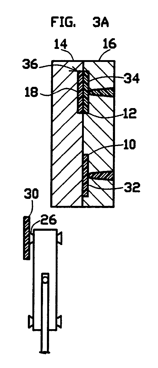
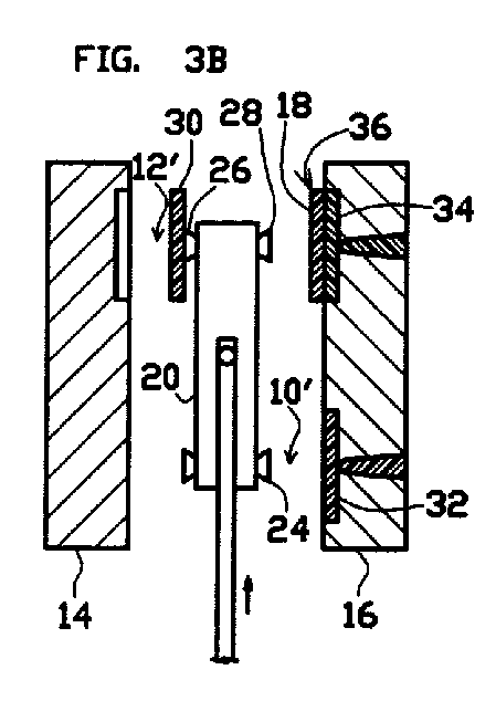
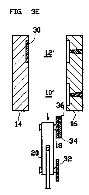
- the mold is then closed, as shown in FIG. 2F, to commence a third closed-mold interval of inaccessibility; whereupon the robot arm 20 is rotated 180 degrees so that the second article 30 attached to the third attachment mechanism 26 of the robot arm 20 assumes the position shown in FIG. 3A.
- the robot arm 20 moves with one continuous movement from outside of the space between the separated first and second mold parts 14, 16 to the predetermined depth of penetration in such space where the common robot arm 20 both releases the first article 18 at the second mold-cavity position 12' and attaches onto the second article 30 at the first mold cavity position 10'; and from the predetermined depth of penetration the common robot arm 20 moves with one continuous movement to outside of such space.
- the attachment mechanisms 22, 24, 26, 28 are not extended from the robot arm 20 in order to attach onto an article or in order to place an article in a cavity-defining portion of a mold part while the robot arm remains in a stationary lateral position, as described above, but instead the robot arm 20 is moved laterally toward and away from the respective separated first and second mold parts 14, 16 in order to enable the respective attachment mechanisms 22, 24, 26, 28 to attach onto an article or to place an article in a cavity-defining portion of a mold part
- a third article 32 is formed in the first mold cavity 10 by injection molding; and the first article 18 is combined with a second component 34 of a product 36 by forming the second component 36 in the second mold cavity 12 by injection molding.
- the first article 18, the second article 30 and the third article 32 are identical.
- the injection-molded third article 32 and the injection molded second component 34 of the product 36 have cooled sufficiently, the first and second mold parts 14, 16 are separated to open the mold.
- the robot arm 20 is again moved to the predetermined depth of penetration into the space between the separated first and second mold parts 14, 16 to move the second article 30 attached to the third attachment mechanism 26 to the second mold-cavity position 12', to move the second attachment mechanism 24 to the first mold-cavity position 10' and to move the fourth attachment mechanism 28 to the second mold cavity position 12'. All of such movements are simultaneous.
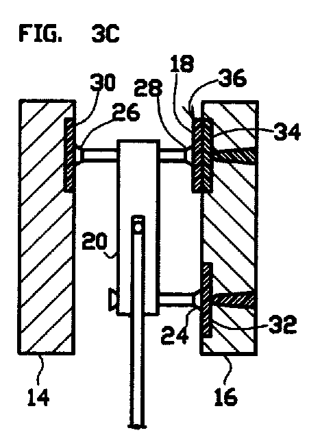
- the fourth attachment mechanism 28 is extended to attach onto the product 36 that includes the first article 18; the third attachment mechanism 26 is extended to place the second article 30 in the portion of the first mold part 14 that partially defines the second mold cavity 12; and the second attachment mechanism 24 is extended to attach onto the third article 32, as shown in FIG. 3C.
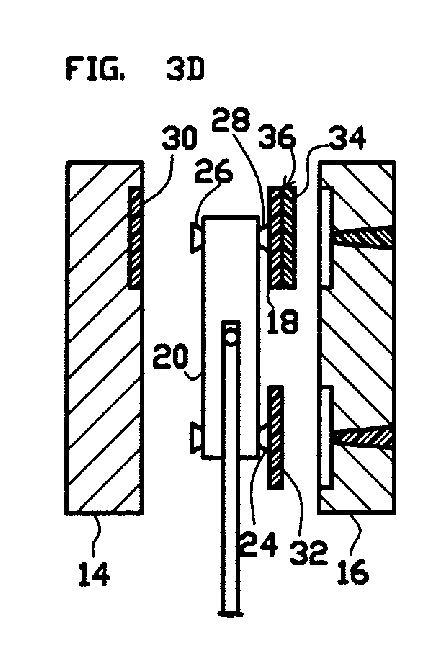
- the fourth attachment mechanism 28 is retracted to withdraw the attached product 36 that includes the first article 18 from the second mold part 16; the third attachment mechanism 26 releases the second article 30, which remains in the portion of the first mold part 14 that partially defines the second mold cavity 12 while the second attachment mechanism 24 is retracted; and the second attachment mechanism 24 is retracted to withdraw the attached third article 32 from the second mold part 16, as shown in FIG. 3D.
- the robot arm 20 is then moved from the space between the separated first and second mold parts 14, 16 to simultaneously move both the attached product 36 that includes the first article 18 from the second position 12' and the attached third article 32 from the first position 10' to outside of the space between the separated first and second mold parts 14, 16, as shown in FIG. 3E.
- the mold is then closed, as shown in FIG. 3F, to commence a fourth closed-mold interval of inaccessibility; whereupon the fourth attachment mechanism 28 releases the product 36 and then the robot arm 20 is rotated 180 degrees so that the third article 32 attached to the second attachment mechanism 24 is reoriented for movement to the second mold-cavity position 12' within the space between the separated mold parts 14, 16 during a fourth period of accessibility following the third interval of inaccessibility.
- the second article 30 is repositioned in the same manner as the first article 18 is repositioned during the third period
- the third article 32 is repositioned in the same manner as the second article 30 is repositioned during the third period
- a fourth article is repositioned in the same manner as the third article 32 is repositioned during the third period.
- a second embodiment of the repositioning method of the present invention is performed during an injection molding process in which a multi-component product having an insert as its first component is produced by injection molding a second component of the product in a first mold cavity 40 containing the insert and repositioning the combined insert and injection-molded second component to a second mold cavity 42 in which a third component of the product is formed in combination with the insert and the second component by injection molding the third component.
- the insert is not necessarily formed by injection molding.
- the insert, or first component of the product is referred to the following description of this second embodiment as an "article".
- the first mold cavity 40 and the second mold cavity 42 are defined between a first mold part 44 and a second mold part 46 during closed-mold intervals of inaccessibility for repositioning of the articles while the mold is closed, as shown in views A and F of FIGS. 4, 5, 6 and 7.
- a space between the first and second mold parts 44, 46 for repositioning of the articles is accessible only during open-mold periods while the mold is opened by separation of the first and second mold parts 44, 46, as shown in views B through E of FIGS. 4, 5, 6 and 7.
- a common robot arm 20 having four extendable attachment mechanisms 22 and 24, 26 and 28 is used to reposition the articles at a first mold-cavity position 40' adjacent those portions of the separated first and second mold parts 44, 46 that define the first mold cavity 40 when the mold is closed, and at a second mold-cavity position 42' adjacent those portions of the separated first and second mold parts 44, 46 that define the second mold cavity 42 when the mold is closed.
- a first article 48 that was placed in the first mold cavity 40 during a previous period of accessibility is combined with a second component 50 of a product by forming the second component 50 in the first mold cavity 40 by injection molding and a second article 52 is attached to the first attachment mechanism 22 of the common robot arm 20.
- the first and second mold parts 44, 46 are separated to open the mold.
- the second component 50 that is combined with the first article 48 is retained in the first-mold-cavity-defining portion of the second mold part 46, as shown in FIG. 4B.
- the common robot arm 20 is moved from outside of the space between the separated first and second mold parts 44, 46 to a predetermined depth of penetration into the space between the mold parts 44, 46 where the first and second attachment mechanisms 22, 24 are disposed at a first mold-cavity position 40' adjacent those portions of the separated first and second mold parts 44, 46 that define the first mold cavity 40 when the mold is closed, and the third and fourth second attachment mechanisms 26, 28 are disposed at a second mold-cavity position 42' adjacent those portions of the separated first and second mold parts 44, 46 that define the second mold cavity 42 when the mold is closed.
- the first attachment mechanism 22 is extended to place the attached second article 52 article in the portion of the first mold part 44 that partially defines the first mold cavity 40; and the second attachment mechanism 24 is extended to attach onto the first article 48, as shown in FIG. 4C.
- the first attachment mechanism 22 releases the second article 52, which remains in the portion of the first mold part 44 that partially defines the first mold cavity 42 while the first attachment mechanism 22 is retracted; and the second attachment mechanism 24 is retracted to withdraw the attached first article 48 from the second mold part 46, as shown in FIG. 4D.
- the robot arm 20 is then moved from the space between the separated first and second mold parts 44, 46 to move the attached first article 48 and the second component 50 combined therewith from the first position 40' to outside of the space between the separated first and second mold parts 44, 46, as shown in FIG. 4E.
- the mold is then closed, as shown in FIG. 4F, to commence a second closed-mold interval of inaccessibility; whereupon the robot arm 20 is rotated 180 degrees so that the first article 48 attached to the second attachment mechanism 24 of the robot arm 20 assumes the position shown in FIG. 5A.
- a second component 54 of another product of which the second article 52 is the first component is formed in the first mold cavity 40 by injection molding and a third article 56 is attached to the fourth attachment mechanism 28 of the common robot arm 20.
- the injection-molded second component 54 of the product that includes the second article 52 has cooled sufficiently, the first and second mold parts 44, 46 are separated to open the mold.
- the first and second mold parts 44, 46 are separated the second component 54 that is combined with the second article 52 is retained in the first-mold-cavity-defining portion of the second mold part 46, as shown in FIG. 5B.
- the robot arm 20 is again moved to the predetermined depth of penetration into the space between the separated first and second mold parts 44, 46 to move the first article 48 attached to the second attachment mechanism 24 to the second mold-cavity position 42', to move the third article 56 attached to the fourth attachment mechanism 28 to the first mold-cavity position 40' and to move the third attachment mechanism 26 to the first mold-cavity position 40'. All of such movements are simultaneous.
- the second attachment mechanism 24 is extended to place the attached first article 48 and the second component 50 combined therewith in the portion of the first mold part 44 that partially defines the second mold cavity 42
- the third attachment mechanism 26 is extended to attach onto the second article 52 having the second component 54 combined therewith
- the fourth attachment mechanism 28 is extended to place the attached third article 56 in the portion of the first mold part 44 that partially defines the first mold cavity 40, as shown in FIG. 5C.
- the second attachment mechanism 24 releases the first article 48 and the second component 50 combined therewith, which remain in the portion of the first mold part 44 that partially defines the second mold cavity 42 while the second attachment mechanism 24 is retracted; the third attachment mechanism 26 is retracted to withdraw the attached second article 52 and the second component 56 combined therewith from the second mold part 46; and the fourth attachment mechanism 28 releases the third article 56, which remains in the portion of the first mold part 44 that partially defines the first mold cavity 40 while the fourth attachment mechanism 28 is retracted, as shown in FIG. 5D.
- the robot arm 20 is then moved from the space between the separated first and second mold parts 44, 46 to move the attached second article 52 having the second component 54 combined therewith from the first position 10' to outside of the space between the separated first and second mold parts 44, 46, as shown in FIG. 5E.
- the mold is then closed, as shown in FIG. 5F, to commence a third closed-mold interval of inaccessibility; whereupon the robot arm 20 is rotated 180 degrees so that the second article 52 attached to the third attachment mechanism 26 of the robot arm 20 assumes the position shown in FIG. 6A.
- the robot arm 20 moves with one continuous movement from outside of the space between the separated first and second mold parts 44, 46 to the predetermined depth of penetration in such space where the common robot arm 20 both releases the first article 48 at the second mold-cavity position 42' and attaches onto the second article 52 at the first mold cavity position 40'; and from the predetermined depth of penetration the common robot arm 20 moves with one continuous movement to outside of such space.
- a second component 58 of still another product of which the third article 56 is the first component is formed in the first mold cavity 40 by injection molding; a third component 60 of a product 62, of which the first article 48 is the first component, is formed in the second mold cavity 42 by injection molding; and a fourth article 64 is attached to the first attachment mechanism 22 of the common robot arm 20.
- the first article 48, the second article 48, the third article 56 and the fourth article 64 are identical.
- the second component 58 that is combined with the third article 56 is retained in the first-mold-cavity-defining portion of the second mold part 46 and the product 62 that includes the first article 48 is retained in the second-mold-cavity-defining portion of the second mold part 46, as shown in FIG. 6B.
- the robot arm 20 is again moved to the predetermined depth of penetration into the space between the separated first and second mold parts 44, 46 to move the second article 52 attached to the third attachment mechanism 26 to the second mold-cavity position 42'; to move the fourth article 64 attached to the first attachment mechanism 22 to the first mold-cavity position 40'; to move the second attachment mechanism 24 to the first mold-cavity position 40'; and to move the fourth attachment mechanism 28 to the second mold cavity position 42'. All of such movements are simultaneous.
- the fourth attachment mechanism 28 is extended to attach onto the product 62 that includes the first article 48; the third attachment mechanism 26 is extended to place the attached second article 52 and the second component 54 combined therewith in the portion of the first mold part 44 that partially defines the second mold cavity 42; the second attachment mechanism 24 is extended to attach onto the third article 56; and the first attachment mechanism 22 is extended to place the attached fourth article 64 in the portion of the first mold part 44 that partially defines the first mold cavity 40, as shown in FIG. 6C.
- the fourth attachment mechanism 28 is retracted to withdraw the attached product 62 that includes the first article 48 from the second mold part 46; the third attachment mechanism 26 releases the second article 52 and the second component 54 combined therewith, which remain in the portion of the first mold part 44 that partially defines the second mold cavity 42 while the third attachment mechanism 26 is retracted; and the second attachment mechanism 24 is retracted to withdraw the attached third article 56 and the second component 58 combined therewith from the second mold part 46; and the first attachment mechanism 22 releases the fourth article 64, which remains in the portion of the first mold part 44 that partially defines the first mold cavity 40 while the first attachment mechanism 22 is retracted, as shown in FIG. 6D.
- the robot arm 20 is then moved from the space between the separated first and second mold parts 44, 46 to simultaneously move both the attached product 62 that includes the first article 48, from the second position 42' and the attached third article 56 having the second component 58 combined therewith from the first position 40' to outside of the space between the separated first and second mold parts 44, 46, as shown in FIG. 6E.
- the mold is then closed, as shown in FIG. 6F, to commence a fourth closed-mold interval of inaccessibility; whereupon the fourth attachment mechanism 28 releases the product 62 and then the robot arm 20 is rotated 180 degrees so that the third article 56 attached to the second attachment mechanism 24 assumes the position shown in FIG. 7A.
- a second component 66 of a further product of which the fourth article 64 is the first component is formed in the first mold cavity 40 by injection molding; and a third component 67 of the second product 68, of which the second article 52 is the first component, is formed in the second mold cavity 42 by injection molding.
- the injection-molded third component 67 of the second product 68 that includes the second article 52 and the second component 67 of the product that includes the fourth article 64 have cooled sufficiently, the first and second mold parts 44, 46 are separated to open the mold.
- the second component 66 that is combined with the fourth article 64 is retained in the first-mold-cavity-defining portion of the second mold part 46 and the second product 68 that includes the second article 52 is retained in the second-mold-cavity-defining portion of the second mold part 46, as shown in FIG. 7B.
- the robot arm 20 is again moved to the predetermined depth of penetration into the space between the separated first and second mold parts 44, 46 to move the third article 56 attached to the second attachment mechanism 24 to the second mold-cavity position 42'; to move the third attachment mechanism 26 to the first mold-cavity position 40'; and to move the first attachment mechanism 22 to the second mold cavity position 42'. All of such movements are simultaneous.
- the first attachment mechanism 22 is extended to attach onto the second product 68 that includes the second article 52; the second attachment mechanism 24 is extended to place the attached third article 56 and the second component 58 combined therewith in the portion of the first mold part 44 that partially defines the second mold cavity 42; and the third attachment mechanism 26 is extended to attach onto the fourth article 56, as shown in FIG. 7C.
- the first attachment mechanism 22 is retracted to withdraw the attached second product 68 that includes the second article 52 from the second mold part 46; the second attachment mechanism 24 releases the attached third article 56 and the second component 58 combined therewith, which remain in the portion of the first mold part 44 that partially defines the second mold cavity 42 while the second attachment mechanism 24 is retracted; the third attachment mechanism 26 is retracted to withdraw the attached fourth article 64 and the second component 66 combined therewith from the second mold part 16, as shown in FIG. 7D.
- the robot arm 20 is then moved from the space between the separated first and second mold parts 44, 46 to simultaneously move both the attached second product 68 that includes the second article 52 from the second position 42' and the attached fourth article 64 having the second component 66 combined therewith from the first position 40' to outside of the space between the separated first and second mold parts 44, 46, as shown in FIG. 7E.
- the mold is then closed, as shown in FIG. 7F, to commence a fifth closed-mold interval of inaccessibility; whereupon the first attachment mechanism 22 releases the second product 68 and then the robot arm 20 is rotated 180 degrees so that the fourth article 64 attached to the third attachment mechanism 26 is reoriented for movement to the second mold-cavity position 42' within the space between the separated mold parts 44, 46 during a fifth period of accessibility following the fifth interval of inaccessibility.
- the third article 56 is repositioned in the same manner as the first article 48 is repositioned during the third period, and the fourth article 64 is repositioned in the same manner as the second article 52 is repositioned during the third period.
- a third embodiment of the repositioning method of the present invention is performed during an injection molding process in which a multi-component product is produced by injection molding a first component of the product in a first mold cavity 70, repositioning the first component to a second mold cavity 72 in which a second component of the product is formed in combination with the first component by injection molding, and repositioning the combined first and second components to a third mold cavity 73 in which a third component of the product is formed in combination with the combined first and the second components by injection molding.
- the first component of the product is referred to the following description of this third embodiment as an "article".
- the first mold cavity 70, the second mold cavity 72 and the third mold cavity 73 are defined between a first mold part 74 and a second mold part 76 during closed-mold intervals of inaccessibility for repositioning of the articles while the mold is closed, as shown in views A and F of FIGS. 8, 9, 10, 11 and 12.
- a space between the first and second mold parts 74, 76 for repositioning of the articles is accessible only during open-mold periods while the mold is opened by separation of the first and second mold parts 74, 76, as shown in views B through E of FIGS. 8, 9, 10, 11 and 12.
- a common robot arm 78 having first, second, third, fourth, fifth and sixth extendable attachment mechanisms 79, 80, 81, 82, 83 and 84 is used to reposition the articles at a first mold-cavity position 70' adjacent those portions of the separated first and second mold parts 74, 76 that define the first mold cavity 70 when the mold is closed, at a second mold-cavity position 72' adjacent those portions of the separated first and second mold parts 74, 76 that define the second mold cavity 72 when the mold is closed and at a third mold-cavity position 73' adjacent those portions of the separated first and second mold parts 74, 76 that define the third mold cavity 73 when the mold is closed.
- the second and fourth attachment mechanisms 80, 82 are mounted on a first member 86 that is rotatable for interchanging the relative positions of the second and fourth attachment mechanisms 80, 82 on the robot arm 78 and the third and fifth attachment mechanisms 81, 83 are mounted on a second member 87 that is rotatable for interchanging the positions of the third and fifth attachment mechanisms 81, 83 on the robot arm 78, as shown in FIG. 13C.
- the robot arm 78 is rotatable, as shown in FIG. 13D, for inversely interchanging the positions of the attachment mechanisms 79, 81, 83 on one side of the robot arm 78 with the positions of the attachment mechanisms 80, 82, 84 on the other side of the robot arm 78.
- a first article 90 is formed in the first mold cavity 70 by injection molding. After the injection-molded first article 90 has cooled sufficiently, the first and second mold parts 74, 76 are separated to open the mold. When the first and second mold parts 74, 76 are separated, the first article 90 is retained in the first-mold-cavity-defining portion of the second mold part 76, as shown in FIG. 8B.
- the common robot arm 78 is moved from outside of the space between the separated first and second mold parts 74, 76 to a predetermined depth of penetration into the space between the mold parts 74, 76 where the first and second attachment mechanisms 79, 80 are disposed at the first mold-cavity position 70', the third and fourth attachment mechanism 81, 82 are disposed at the second mold-cavity position 72' and the fifth and sixth attachment mechanisms 83, 84 are disposed at the third mold-cavity position 73'.
- the robot arm 78 After the robot arm 78 is moved to the predetermined depth of penetration into the space between the separated first and second mold parts 74, 76, the second attachment mechanism 80 is extended to attach onto the first article 90, as shown in FIG. 8C.
- the second attachment mechanism 80 is then retracted to withdraw the attached first article 90 from the second mold part 76, as shown in FIG. 8D.
- the robot arm 78 is then moved from the space between the separated first and second mold parts 74, 76 to move the attached first article 90 from the first position 70' to outside of the space between the separated first and second mold parts 74, 76, as shown in FIG. 8E.
- the mold is then closed, as shown in FIG. 8F, to commence a second closed-mold interval of inaccessibility; whereupon the first member 86 is rotated 180 degrees and the robot arm 78 is rotated 180 degrees so that the first article 90 attached to the second attachment mechanism 80 mounted on the first member 86 of the robot arm 78 assumes the position shown in FIG. 9A.
- a second article 91 is formed in the first mold cavity 70 by injection molding .
- the first and second mold parts 74, 76 are separated to open the mold.
- the second article 91 is retained in the first-mold-cavity-defining portion of the second mold part 76, as shown in FIG. 9B.
- the robot arm 78 is again moved to the predetermined depth of penetration into the space between the separated first and second mold parts 74, 76 to move the first article 90 attached to the second attachment mechanism 80 to the second mold-cavity position 72' and to move the fifth attachment mechanism 83 to the first mold-cavity position 70'. All of such movements are simultaneous.
- the second attachment mechanism 80 is extended to place the first article 90 in the portion of the first mold part 74 that partially defines the second mold cavity 72; and the fifth attachment mechanism 83 is extended to attach onto the second article 91, as shown in FIG. 9C.
- the second attachment mechanism 80 releases the first article 90, which remains in the portion of the first mold part 74 that partially defines the second mold cavity 72 while the second attachment mechanism 80 is retracted; and the fifth attachment mechanism 83 is retracted to withdraw the attached second article 91 from the second mold part 76, as shown in FIG. 9D.
- the robot arm 78 is then moved from the space between the separated first and second mold parts 74, 76 to move the attached second article 91 from the first position 70' to outside of the space between the separated first and second mold parts 74, 76, as shown in FIG. 9E.
- the mold is then closed, as shown in FIG. 9F, to commence a third closed-mold interval of inaccessibility; whereupon the second member 87 is rotated 180 degrees and the robot arm 78 is rotated 180 degrees so that the second article 91 attached to the fifth attachment mechanism 83 mounted on the second member 87 of the robot arm 78 assumes the position shown in FIG. 10A.
- the robot arm 78 moves with one continuous movement from outside of the space between the separated first and second mold parts 74, 76 to the predetermined depth of penetration in such space where the common robot arm 78 both releases the first article 90 at the second mold-cavity position 72' and attaches onto the second article 91 at the first mold cavity position 70'; and from the predetermined depth of penetration the common robot arm 78 moves with one continuous movement to outside of such space.
- the attachment mechanisms 79, 80, 81, 82, 83, 84 are not extended from the robot arm 78 in order to attach onto an article or in order to place an article in a cavity-defining portion of a mold part while the robot arm remains in a stationary lateral position, as described above, but instead the robot arm 78 is moved laterally toward and away from the respective separated first and second mold parts 74, 76 in order to enable the respective attachment mechanisms 79, 80, 81, 82, 83, 84 to attach onto an article or to place an article in a cavity-defining portion of a mold part
- a third article 92 is formed in the first mold cavity 70 by injection molding; and the first article 90 is combined with a second component 93 of a product by forming the second component 93 in the second mold cavity 72 by injection molding.
- the first article 90, the second article 91 and the third article 92 are identical.
- the injection-molded third article 92 and the injection molded second component 93 of the product have cooled sufficiently, the first and second mold parts 74, 76 are separated to open the mold.
- the robot arm 78 is again moved to the predetermined depth of penetration into the space between the separated first and second mold parts 74, 76 to move the second article 91 attached to the fifth attachment mechanism 83 to the second mold-cavity position 72', to move the second attachment mechanism 80 to the second mold-cavity position 72' and to move the fourth attachment mechanism 82 to the first mold cavity position 70'. All of such movements are simultaneous.
- the second attachment mechanism 80 is extended to attach onto the first article 90 and the second component 93 combined therewith; the fifth attachment mechanism 83 is extended to place the second article 91 in the portion of the first mold part 74 that partially defines the second mold cavity 72; and the fourth attachment mechanism 82 is extended to attach onto the third article 92, as shown in FIG. 10C.
- the second attachment mechanism 80 is retracted to withdraw the attached first article 90 and the second component 93 combined therewith from the second mold part 76; the fifth attachment mechanism 83 releases the second article 91, which remains in the portion of the first mold part 74 that partially defines the second mold cavity 72 while the fifth attachment mechanism 83 is retracted; and the fourth attachment mechanism 82 is retracted to withdraw the attached third article 92 from the second mold part 76, as shown in FIG. 10D.
- the robot arm 78 is then moved from the space between the separated first and second mold parts 74, 76 to simultaneously move both the attached first article 90 and the second component 93 combined therewith from the second position 72' and the attached third article 92 from the first position 70' to outside of the space between the separated first and second mold parts 74, 76, as shown in FIG. 10E.
- the mold is then closed, as shown in FIG. 10F, to commence a fourth closed-mold interval of inaccessibility; whereupon the first member 86 is rotated 180 degrees and the robot arm 78 is rotated 180 degrees so that the combination of the first article 90 and the second component 93 attached to the second attachment mechanism 80 and the third article 92 attached to the fourth attachment mechanism 82 assume the respective positions shown in FIG. 11A.
- a fourth article 94 is formed in the first mold cavity 70 by injection molding; and the second article 91 is combined with a second component 95 of another product by forming the second component 95 in the second mold cavity 72 by injection molding.
- the injection-molded fourth article 94 and the injection molded second component 95 of the other product have cooled sufficiently, the first and second mold parts 74, 76 are separated to open the mold.
- the robot arm 78 is again moved to the predetermined depth of penetration into the space between the separated first and second mold parts 74, 76 to move the combination of the first article 90 and the second component 93 attached to the second attachment mechanism 80 to the third mold-cavity position 73', to move the third article 92 attached to the fourth attachment mechanism 82 to the second mold-cavity position 72', to move the fifth attachment mechanism 83 to the second mold-cavity position 72' and to move the third attachment mechanism 81 to the first mold cavity position 70'. All of such movements are simultaneous.
- the second attachment mechanism 80 is extended to place the first article 90 and the second component 93 combined therewith in the portion of the first mold part 74 that partially defines the third mold cavity 73; the fifth attachment mechanism 83 is extended to attach onto the second article 91 and the second component 95 combined therewith; the fourth attachment mechanism 82 is extended to place the third article 92 in the portion of the first mold part 74 that partially defines the second mold cavity 72; and the third attachment mechanism 81 is extended to attach onto the fourth article 94, as shown in FIG. 11C.
- the second attachment mechanism 80 releases the combination of the first article 90 and the second component 93, which remains in the portion of the first mold part 74 that partially defines the third mold cavity 73 while the second attachment mechanism 80 is retracted; the fifth attachment mechanism 83 is retracted to withdraw the attached second article 91 and the second component 95 combined therewith from the second mold part 76; the fourth attachment mechanism 82 releases the third article 92, which remains in the portion of the first mold part 74 that partially defines the second mold cavity 72 while the fourth attachment mechanism 82 is retracted; and the third attachment mechanism 81 is retracted to withdraw the attached fourth article 94 from the second mold part 76, as shown in FIG. 11D.
- the robot arm 78 is then moved from the space between the separated first and second mold parts 74, 76 to simultaneously move both the attached second article 91 and the second component 95 combined therewith from the second position 72' and the attached fourth article 94 from the first position 70' to outside of the space between the separated first and second mold parts 74, 76, as shown in FIG. 11E.
- the mold is then closed, as shown in FIG. 11F, to commence a fifth closed-mold interval of inaccessibility; whereupon the second member 87 is rotated 180 degrees and the robot arm 78 is rotated 180 degrees so that the combination of the second article 91 and the second component 95 attached to the fifth attachment mechanism 83 and the fourth article 94 attached to the third attachment mechanism 81 assume the respective positions shown in FIG. 12A.
- a fifth article 96 is formed in the first mold cavity 70 by injection molding; the combination of the first article 90 and the second component 93 is combined with a third component 97 of the product 98 by forming the third component 97 in the third mold cavity 73 by injection molding; and the third article 92 is combined with a second component 99 of still another product by forming the second component 99 in the second mold cavity 72 by injection molding.
- the injection-molded fifth article 96, the injection molded third component 97 of the product 98 and the injection molded second component 99 of the still another product have cooled sufficiently, the first and second mold parts 74, 76 are separated to open the mold.
- the fifth article 96 is retained in the first-mold-cavity-defining portion of the second mold part 76
- the product 98 that includes the first article 90 is retained in the third-mold-cavity-defining portion of the second mold part 76
- the third article 92 and the second component 99 combined therewith are retained in the second-mold-cavity-defining portion of the second mold part 76, as shown in FIG. 12B.
- the robot arm 78 is again moved to the predetermined depth of penetration into the space between the separated first and second mold parts 74, 76 to move the sixth attachment mechanism 84 to the third mold-cavity position 73', to move the combination of the second article 91 and the second component 95 attached to the fifth attachment mechanism 83 to the third mold-cavity position 73', to move the fourth article 94 attached to the third attachment mechanism 81 to the second mold-cavity position 72', to move the fourth attachment mechanism 82 to the second mold-cavity position 72' and to move the second attachment mechanism 80 to the first mold cavity position 70'. All of such movements are simultaneous.
- the sixth attachment mechanism 84 is extended to attach onto the product 98 that includes the first article 90; the fifth attachment mechanism 83 is extended to place the second article 91 and the second component 95 combined therewith in the portion of the first mold part 74 that partially defines the third mold cavity 73; the fourth attachment mechanism 82 is extended to attach onto the third article 92 and the second component 99 combined therewith; the third attachment mechanism 81 is extended to place the fourth article 94 in the portion of the first mold part 74 that partially defines the second mold cavity 72; and the second attachment mechanism 80 is extended to attach onto the fifth article 96, as shown in FIG. 12C.
- the sixth attachment mechanism 84 is retracted to withdraw the attached product 98 that includes the first article 90 from the second mold part 76; the fifth attachment mechanism 83 releases the combination of the second article 91 and the second component 95, which remains in the portion of the first mold part 74 that partially defines the third mold cavity 73 while the fifth attachment mechanism 83 is retracted; the fourth attachment mechanism 82 is retracted to withdraw the attached third article 92 and the second component 99 combined therewith from the second mold part 76; the third attachment mechanism 81 releases the fourth article 94, which remains in the portion of the first mold part 74 that partially defines the second mold cavity 72 while the third attachment mechanism 81 is retracted; and the second attachment mechanism 80 is retracted to withdraw the attached fifth article 96 from the second mold part 76, as shown in FIG. 11D.
- the robot arm 78 is then moved from the space between the separated first and second mold parts 74, 76 to simultaneously move all three of the attached product 98 that includes the first article 90 from the third position 73', the attached third article 92 and the second component 99 combined therewith from the second position 72' and the attached fifth article 96 from the first position 70' to outside of the space between the separated first and second mold parts 74, 76, as shown in FIG. 12E.
- the mold is then closed, as shown in FIG. 12F, to commence a sixth closed-mold interval of inaccessibility; whereupon the sixth attachment mechanism 22 releases the product 98 that includes the first article 90 and then the first member 86 is rotated 180 degrees and the robot arm 78 is rotated 180 degrees so that the combination of the third article 92 and the second component 99 attached to the fourth attachment mechanism 82 and the fifth article 96 attached to the second attachment mechanism 80 are reoriented for movement to the third mold-cavity position 73' and the second mold-cavity position 72' respectively within the space between the separated mold parts 74, 76 during a sixth period of accessibility following the sixth interval of inaccessibility.
- the second article 91 is repositioned in the same manner as the first article 90 is repositioned during the fifth period
- the third article 92 is repositioned in the same manner as the second article 91 is repositioned during the fifth period
- the fourth article 94 is repositioned in the same manner as the third article 92 is repositioned during the fifth period.
- a fourth embodiment of the repositioning method of the present invention is performed during an injection molding process in which articles that constitute components of products are repositioned within a plurality of spaces between adjacent mold parts of a stack mold that define mold cavities when respective pairs of the mold parts are combined in the course of producing multi-component products. These spaces are accessible for such repositioning only during respective series of open-mold periods that are separated by closed-mold intervals of inaccessibility for such repositioning.
- the first component of the product is referred to the following description of this fourth embodiment as an "article".
- a first portion of the stack mold includes a first mold part 102 paired with a second mold part 103, which when combined, as shown in FIG. 14F, define a first mold cavity 104 and a second cavity 105; and a second portion of the stack mold includes a third mold part 107 paired with a fourth mold part 108, which when combined, as shown in FIG. 14L, define a third mold cavity 109 and a fourth cavity 110.
- the first, second, third and fourth mold parts 102, 103, 107, 108 are respectively disposed in seriatim adjacent each other for movement along a common axis.
- a first space between the first and second mold parts 102, 103 is accessible for repositioning of the articles only during a first series of open-mold periods while the first portion of the mold is opened by separation of the first and second mold parts 102, 103, as shown in views B through E of FIG. 14, with an intervening closed-mold interval of inaccessibility of the first series being shown in views F through A.
- a second space between the third and fourth mold parts 107, 108 is accessible for repositioning of the articles only during a second series of open-mold periods while the second portion of the mold is opened by separation of the third and fourth mold parts 107, 108, as shown in views H through K of FIG.
- the first space is accessible only during a closed-mold interval in the second series of open-mold periods pertaining to the second space; and the second space is accessible only during a closed-mold interval in the first series of open-mold periods pertaining to the first space
- the articles are repositioned between the respective mold cavities 104 and 110, 109 and 105 by means of a common robot arm 112, which includes first, second, third and fourth extendable attachment mechanism 113, 114, 115 and 116 that are so positioned on the robot arm 112 that when the robot arm 112 is moved from outside of the first space between the separated first and second mold parts 102, 103 to a predetermined depth of penetration into the first space between the first and second mold parts 102, 103, as shown in FIG.
- the first and second attachment mechanisms 113, 114 are disposed at a first mold-cavity position 104' respectively adjacent those portions of the separated first and second mold parts 102, 103 that define the first mold cavity 104 when the first portion of the mold is closed
- the third and fourth attachment mechanisms 115, 116 are disposed at a second mold-cavity position 105' respectively adjacent those portions of the separated first and second mold parts 102, 103 that define the second mold cavity 105 when the first portion of the mold is closed.
- the positioning of the attachment mechanisms 113, 114, 115, 116 on the robot arm 112 is also such that when the robot arm 112 is moved from outside of the second space between the separated third and fourth mold parts 107, 108 to a predetermined depth of penetration into the second space between the third and fourth mold parts 107, 108, as shown in FIG.
- the third and fourth attachment mechanisms 115, 116 are disposed at a third mold-cavity position 109' respectively adjacent those portions of the separated third and fourth mold parts 107, 108 that define the third mold cavity 109 when the second portion of the mold is closed
- the first and second attachment mechanisms 113, 114 are disposed at a fourth mold-cavity position 110' respectively adjacent those portions of the separated third and fourth mold parts 107, 108 that define the fourth mold cavity 110 when the second portion of the mold is closed.
- a first article 118 is moved from the first mold-cavity position 104' within the first space to outside of both the first space and the second space during an open-mold period of the first series of open-mold periods when the first space between the first pair of the first and second mold parts 102, 103 is accessible, while the second space between the second pair of the third and fourth mold parts 107, 108 is inaccessible for repositioning; and the first article 118 subsequently is moved from outside of the first space and the second space to the fourth mold-cavity position 110' within the second space during an open-mold period of the second series when the second space between the second pair of the third and fourth mold parts 107, 108 is accessible, while the first space between the first pair of the first and second mold parts 102, 103 is inaccessible for repositioning.
- the first and second mold parts 102, 103 are separated, whereupon a first article 118 formed in the first mold cavity 104 during the preceding closed-mold interval of the first series is retained in the first-mold-cavity-defining portion of the second mold part 103 and a product 120 that includes a second article 122 combined with a second component 124 formed in the second mold cavity 105 during the preceding closed-mold interval of the first series is retained in the second-mold-cavity-defining portion of the second mold part 103; and the common robot arm 112 is moved to the predetermined depth of penetration into the first space between the separated first and second mold parts 102, 103 in order to dispose the second attachment mechanism 114 of the robot arm 112 at the first mold-cavity position 104' and in order to dispose the fourth attachment mechanism 116 at the second mold-cavity position 105'.
- the first article 118 formed in the first mold cavity 104 during the preceding closed-mold interval of the first series is retained in the first-mold-ca
- the second attachment mechanism 114 is extended to attach onto the first article 118 and the fourth attachment mechanism 116 is extended to attach onto the product 120 that includes the second article 122, as shown in FIG. 14C.
- the second attachment mechanism 114 is retracted to withdraw the attached first article 118 from the second mold part 103 and the fourth attachment mechanism 116 is retracted to withdraw the attached product 120 that includes the second article 122 from the second mold part 103, as shown in FIG. 14D.
- the robot arm 112 is then moved from the first space between the separated first and second mold parts 102, 103 to simultaneously move both the attached first article 118 from the first position 104' and the attached product 120 that includes the second article 122 from the second position 105' to outside of the first space between the separated first and second mold parts 102, 103, as shown in FIG. 14E.
- the first portion of the mold is then closed, as shown in FIG. 14F, to commence a another closed-mold interval of inaccessibility of the first series; whereupon the fourth attachment mechanism 116 releases the product 120 that includes the second article 122 and then the robot arm 118 is rotated 180 degrees so that the first article 118 attached to the second attachment mechanism 114 of the robot arm 112 assumes the position shown in FIG. 14G.
- the third and fourth mold parts 107, 108 are separated, whereupon a third article 126 formed in the third mold cavity 109 during the preceding closed-mold interval of the second series is retained in the third-mold-cavity-defining portion of the third mold part 107 and a product 128 that includes a fourth article 130 combined with a second component 132 formed in the fourth mold cavity 110 during the preceding closed-mold interval of the second series is retained in the fourth-mold-cavity-defining portion of the third mold part 107; and the common robot arm 112 is moved to the predetermined depth of penetration into the second space between the separated third and fourth mold parts 107, 108 in order to move the first article 118 attached to the second attachment mechanism 114 to the fourth mold-cavity position 110', in order to dispose the third attachment mechanism 115 at the third mold-cavity position 109' and in order to dispose the first attachment mechanism 113 at the fourth mold-
- the second attachment mechanism 114 is extended to place the first article 118 in the portion of the fourth mold part 108 that partially defines the fourth mold cavity 110; the third attachment mechanism 115 is extended to attach onto the third article 126 and the first attachment mechanism 113 is extended to attach onto the product 128 that includes the fourth article 130, as shown in FIG. 14I.
- the second attachment mechanism 114 releases the first article 118, which remains in the portion of the fourth mold part 108 that partially defines the fourth mold cavity 110 while the second attachment mechanism 114 is retracted; the third attachment mechanism 115 is retracted to withdraw the attached third article 126 from the third mold part 107 and the first attachment mechanism 113 is retracted to withdraw the attached product 128 that includes the fourth article 130 from the third mold part 107, as shown in FIG. 14J.
- the robot arm 112 is then moved from the second space between the separated third and forth mold parts 107, 108 to simultaneously move both the attached third article 126 from the third position 109' and the attached product 128 that includes the fourth article 130 from the fourth position 110' to outside of the second space between the separated third and fourth mold parts 107, 108, as shown in FIG. 14K.
- the second portion of the mold is then closed, as shown in FIG. 14L, to commence another closed-mold interval of inaccessibility of the second series; whereupon the first attachment mechanism 113 releases the product 128 that includes the fourth article 130 and then the robot arm 112 is rotated 180 degrees so that the third article 126 attached to the third attachment mechanism 115 of the robot arm 112 assumes the position shown for article 126' in FIG. 14A.
- the repositioning method continues through another sequence of steps such as shown in FIGS. 14A through 14L, with a product that includes the first article 118 being moved from the fourth mold cavity position 110' to outside of the second space during the next open-mold period of the second series by a step such as that shown in FIG. 14K, in which the product 128 that includes the fourth article 130 is so moved.
- the fourth embodiment of the repositioning method is quite similar to the first embodiment of repositioning method shown in FIGS 1A through 1F, FIGS. 2A through 2F and FIGS. 3A through 3F, wherein during an open-mold period (a) two different articles are moved simultaneously by a common robot arm from different mold cavity positions within a space between separated mold parts to outside of such space; and (b) one article is moved from outside of such space to a given mold-cavity position within such space by means of a common robot arm that is also used to move another article from the same mold-cavity position to outside of such space.
- the other features of the first embodiment described hereinabove that are not incompatible with the fourth embodiment are also included in the fourth embodiment.
- Utilization of the fourth embodiment of the repositioning method of the present invention with a desynchronously opened stack mold, as described above, enables articles to be repositioned more quickly in that one article can be repositioned into a space in a different portion of the mold than the portion from which the one article was moved while another article that was subsequently injection-molded in the portion of the stack mold from which the one article was moved is cooling.
- the respective components of the multi-component products may be made of different plastic materials and/or of different colors. There is no upper limitation as to the number of components; and the relative positioning of the different mold cavities may be other than the linear alignments shown in the Drawing.
- additional products can also be injection molded between the same pair(s) of mold parts as are used to form multi-component products through utilization of the repositioning methods.
- Such additional products may be either single component products or multi-component products; and such additional multi-component products may include a plurality of identical and/or dissimilar products of which one or more components are repositioned in accordance with the present invention.
- the repositioning methods of the present invention can be utilized with injection-molding processes other than those described herein.
- the repositioning methods of the present invention can be utilized with a core-back injection molding process, in which a core is retracted following injection of a first plastic material into a mold cavity in order to enable injection of a second plastic material into the mold cavity without separating the mold parts between such injections of the plastic material, such that at least one of the components of the multi-component product formed through utilization of the repositioning method may be multi-colored and/or composed of different materials.
- a first component formed in the first core-back mold cavity can be a multi-colored and/or multi-material component that is removed from the space between the mold parts during a first open-mold period of accessibility; and after the first component subsequently is moved to the position of the second core-back cavity during a second open-mold period of accessibility, a second multi-colored and/or multi-material component is formed in the second core-back mold cavity during a subsequent closed-mold interval of inaccessibility.
- a core-back injection-molding process for a stack mold is described in U.S. Patent No. 5,049,343 to Jens Ole Sorensen.
- an intermediate closed-mold interval during which a component of an uncompleted multi-component product is outside of the space between the mold parts as a result of being repositioned in accordance with the present invention such component can be subjected to an ancillary process that enhances the final product.
- a product label can be affixed to such component; and then after the component subsequently has been repositioned within the space between the mold parts a transparent plastic layer can be injection molded over the label to thereby provide a product having a sealed label.
- the respective components of the product can be subjected to a different ancillary processes during each such intermediate closed mold interval in which the respective component is outside the space between the mold parts during the overall injection molding process.
- the repositioning methods of the present invention also may be utilized with processes other than injection molding in which certain steps are better carried out either under or apart from special conditions in a space that is sealed from the ambient, such as conditions of extreme heat or cold, high or low pressure, high pollution, poisonous air, high radiation or within a centrifuge.
- an article that has been repositioned during a period of accessibility into a space from which the article was removed during a prior period of accessibility may be subjected to a process, such as heat processing or irradiation, that is more effective during an interval of less accessibility than during a period of accessibility.
- an article that has been moved from a space to outside of the space during a period of accessibility is subjected to a given process during an interval of less accessibility while outside of the space before being moved back into the space during a subsequent period of accessibility.
Landscapes
- Engineering & Computer Science (AREA)
- Manufacturing & Machinery (AREA)
- Mechanical Engineering (AREA)
- Robotics (AREA)
- Moulds For Moulding Plastics Or The Like (AREA)
- Injection Moulding Of Plastics Or The Like (AREA)
Abstract
Description
Claims (17)
- A method of repositioning articles within a space that is accessible for said repositioning only during a series of periods that are separated by intervals of less accessibility for said repositioning, comprising the steps of:wherein said movement of the first article and said movement of the second article are by means of a common vehicle (20).(a) during a first said period, moving a first article (18, 48, 90) from a first position (10', 40', 70') within said space to outside of said space; and(b) during the first period, moving a second article from outside of said space to a second position (12', 42', 72') within said space;
- A method according to Claim 1, further comprising the step of:(c) during a second period after a said interval of inaccessibility that is subsequent to the first period, moving the first article (18, 48, 90) by means of the common vehicle from outside of said space to the second position (12', 42', 72').
- A method of repositioning articles within a space that is accessible for said repositioning only during a series of periods that are separated by intervals of less accessibility for said repositioning, comprising the steps of:(a) during a first said period, moving a first article (18, 48, 90) from a first position (10', 40', 70') within said space to outside of said space; and(b) during the first period, moving an identical second article from outside of said space to a second position (12', 42', 72') within said space.
- A method according to Claim 3, wherein said movement of the first article (18, 48, 90) and said movement of the second article are by means of a common vehicle (20).
- A method of repositioning articles within a space that is accessible for said repositioning only during a series of periods that are separated by intervals of less accessibility for said repositioning than during said periods, comprising the steps of:(a) during a first said period, moving a first article (18, 48, 90) from a first position (10', 40', 70') within said space to outside of said space; and(b) during a second said period after a said interval of less accessibility that is subsequent to the first period, moving the first article from outside of said space to a second position (12', 42', 72') within said space.
- A method according to Claim 5, wherein said movements of the first article (18, 48, 90) during steps (a) and (b) are by means of a common vehicle (20).
- A method according to Claim 5, further comprising the step of:(c) during the second period, moving a second article (30, 52, 91) from the first position (10', 40', 70') to outside of said space.
- A method according to Claim 7, further comprising the step of:(d) during a third said period after a said interval of less accessibility that is subsequent to the second period, moving the second article (30, 52. 91) from outside of said space to the second position (12', 42', 72').
- A method according to Claim 8, further comprising the steps of:(e) during the third period, moving a third article (56, 92) from the first position (40', 70') to outside of said space; and(f) during a fourth said period after a said interval of less accessibility that is subsequent to the third period, moving the third article from outside of said space to the second position (42', 72').
- A method of repositioning an article within a space that is accessible for the repositioning of articles therein only during a series of periods that are separated by intervals of less accessibility for said repositioning than during said periods, comprising the steps of:(a) during a first said period, moving an article (52) from outside of said space to a first position (40') within said space;(b) during a second period after a said interval of less accessibility that is subsequent to the first period, moving the article from the first position to outside of said space; and(c) during a third said period after a said interval of less accessibility that is subsequent to the second period, moving the article from outside of said space to a second position (42') within said space.
- A method according to Claim 10, wherein during a said interval of less accessibility that is subsequent to the first period and prior to the second period, the article (52) is combined with a given object (54).
- A method according to Claim 11, wherein during a said interval of less accessibility that is subsequent to the third period and prior to a fourth said period, the article (52) is further combined with another object (67).
- A method according to any of the preceding claims, wherein the space within which said article(s) are repositioned is located between mold parts (14, 16; 44, 46; 74, 76) that define a plurality of mold cavities when the mold is closed, wherein said space is accessible for said repositioning only during a series of open-mold periods that are separated by closed-mold intervals of inaccessibility for said repositioning.
- A method according to Claim 13 as according to only Claim 10, wherein the article (52) is a first component of a multi-component product (68) of which a second component (54) is formed in the first mold-cavity position (40') by injection molding during a said closed-mold interval of inaccessibility that is subsequent to the first open-mold period and prior to the second open-mold period.
- A method according to Claim 14, wherein a third component (67) of said product (68) is formed in the second mold-cavity position (42') by injection molding during a said closed-mold interval of inaccessibility that is subsequent to the third open-mold period and prior to the fourth open-mold period.
- A method of repositioning articles within a plurality of spaces between adjacent mold parts (102, 103; 107, 108) of a stack mold that define mold cavities when respective pairs of the mold parts are combined, wherein said spaces are accessible for said repositioning only during respective series of open-mold periods that are separated by closed-mold intervals of inaccessibility for said repositioning, the method comprising the steps of:(a) during a first said open-mold period when a first said space between a first said pair of said mold parts (102, 103) is accessible, moving a first article (118) from a mold-cavity position (104') within said first space to outside of said spaces; and(b) during a second said open-mold period when a second said space between a second said pair of said mold parts (107, 108) is accessible, moving the first article from outside of said spaces to a mold-cavity position (110') within said second space.
- A method according to Claim 16, wherein during step (a), the second space is inaccessible for said repositioning; and during step (b), the first space is inaccessible for said repositioning.
Applications Claiming Priority (2)
| Application Number | Priority Date | Filing Date | Title |
|---|---|---|---|
| US08/914,569 US6086808A (en) | 1997-08-19 | 1997-08-19 | Repositioning of articles between different positions within an intermittently accessible space |
| US914569 | 1997-08-19 |
Publications (3)
| Publication Number | Publication Date |
|---|---|
| EP0903213A2 true EP0903213A2 (en) | 1999-03-24 |
| EP0903213A3 EP0903213A3 (en) | 1999-12-22 |
| EP0903213B1 EP0903213B1 (en) | 2002-07-10 |
Family
ID=25434529
Family Applications (1)
| Application Number | Title | Priority Date | Filing Date |
|---|---|---|---|
| EP98306394A Expired - Lifetime EP0903213B1 (en) | 1997-08-19 | 1998-08-11 | Repositioning of articles between different positions within an intermittently accessible space |
Country Status (5)
| Country | Link |
|---|---|
| US (2) | US6086808A (en) |
| EP (1) | EP0903213B1 (en) |
| JP (1) | JPH11170292A (en) |
| CA (1) | CA2245656C (en) |
| DE (2) | DE69806455T2 (en) |
Cited By (9)
| Publication number | Priority date | Publication date | Assignee | Title |
|---|---|---|---|---|
| EP0914921A1 (en) | 1997-11-07 | 1999-05-12 | HERBST, Richard | Method and apparatus for injection moulding of coded cards |
| DE10033759A1 (en) * | 2000-07-12 | 2002-02-07 | Hekuma Herbst Maschb Gmbh | Method and device for injection molding multi-component plastic articles |
| US7165967B2 (en) | 2002-09-17 | 2007-01-23 | Hekuma Gmbh | Method for removing injection-moulded parts from an injection-moulding machine and injection-moulding machine with a handling system |
| WO2007082394A1 (en) | 2006-01-23 | 2007-07-26 | Foboha Gmbh Formenbau | Transfer system for multicomponent injection moulding |
| EP2191951A1 (en) * | 2008-11-29 | 2010-06-02 | Braun Gmbh | Transfer system for a plastic injection device, as well as a plastic injection method carried out including said plastic injection device |
| WO2011072739A1 (en) * | 2009-12-16 | 2011-06-23 | Gm Tec Industries Holding Gmbh | Method and device for producing a fibre-reinforced injection-moulded plastic part |
| EP2812170A4 (en) * | 2012-02-07 | 2015-05-20 | Caco Pacific Corp | Mold and method for molding parts requiring multiple mold inputs |
| WO2018203749A1 (en) | 2017-05-03 | 2018-11-08 | Weener Plastics Group B.V. | Mould for injection moulding a closure assembly |
| EP3718732A1 (en) * | 2019-04-02 | 2020-10-07 | GK Concept GmbH | Method and device for manufacturing multicomponent plastic moulded articles |
Families Citing this family (26)
| Publication number | Priority date | Publication date | Assignee | Title |
|---|---|---|---|---|
| JP3027150B1 (en) * | 1998-11-13 | 2000-03-27 | 大協株式会社 | Method and apparatus for manufacturing hollow body made of synthetic resin incorporating intermediate |
| WO2000073040A1 (en) * | 1999-05-17 | 2000-12-07 | Jes Tougaard Gram | Mould with turnable middle section |
| US6224363B1 (en) * | 1999-07-15 | 2001-05-01 | Pilot Industries, Inc. | System for loading raw material and unloading finished parts from a compression mold |
| US6464922B1 (en) * | 1999-12-10 | 2002-10-15 | Autotec, Inc. | Insertion device for plastic molding |
| JP2002234062A (en) * | 2001-02-08 | 2002-08-20 | Star Seiki Co Ltd | Molding releasing unit and method for cutting gate |
| DE10110611C2 (en) * | 2001-03-06 | 2003-11-27 | Lehmann Gmbh & Co Kg | Device for injection molding molded articles made of plastic |
| JP3609038B2 (en) * | 2001-05-21 | 2005-01-12 | 株式会社日本製鋼所 | Three-layer laminate molding method and molding die |
| DE10152816B4 (en) * | 2001-10-19 | 2004-12-30 | Hekuma Gmbh | Method for producing a multi-part plastic product and device for carrying out the method |
| DE10152815C1 (en) * | 2001-10-19 | 2003-06-18 | Hekuma Gmbh | Handling device for a plastic injection molding machine and gripper for one |
| US20040075189A1 (en) * | 2002-10-16 | 2004-04-22 | Ching-Lin Tai | Method for making dual-color melamine container |
| US20040075190A1 (en) * | 2002-10-16 | 2004-04-22 | Ching-Lin Tai | Method for making melamine container with dual-side patterns |
| DE10331519A1 (en) * | 2003-07-11 | 2005-02-03 | Hekuma Gmbh | Handling system for an injection molding machine and method for introducing an application into the injection mold |
| JP5122829B2 (en) * | 2007-02-15 | 2013-01-16 | 矢崎総業株式会社 | TRANSFER DEVICE AND MOLDED PRODUCT MANUFACTURING DEVICE EQUIPPED WITH THE TRANSFER DEVICE |
| JP2008235489A (en) * | 2007-03-19 | 2008-10-02 | Fujitsu Ltd | Resin sealing method, resin sealing mold, and resin sealing device |
| DE102007018358B4 (en) * | 2007-04-18 | 2016-12-22 | Schoeller Arca Systems Services Gmbh | Relief overmolding |
| ITBO20070385A1 (en) * | 2007-05-31 | 2008-12-01 | Sacmi | UNIT FOR TAKING CERAMIC OR ASSIMILABLE MANUFACTURED ITEMS. |
| KR20090003331U (en) * | 2007-10-05 | 2009-04-09 | 홍종선 | Injection mold for multi-insert container |
| US8198739B2 (en) | 2010-08-13 | 2012-06-12 | Endicott Interconnect Technologies, Inc. | Semi-conductor chip with compressible contact structure and electronic package utilizing same |
| DE102013002519B4 (en) | 2013-02-13 | 2016-08-18 | Adidas Ag | Production method for damping elements for sportswear |
| JP6013261B2 (en) * | 2013-04-11 | 2016-10-25 | Nok株式会社 | Manufacturing method of plate-integrated gasket |
| DE112014002134T5 (en) | 2013-04-25 | 2016-02-18 | Athena Automation Ltd. | In-mold system for an injection molding machine |
| DE102015202013B4 (en) | 2015-02-05 | 2019-05-09 | Adidas Ag | Process for producing a plastic molding, plastic molding and shoe |
| DE102016209046B4 (en) | 2016-05-24 | 2019-08-08 | Adidas Ag | METHOD FOR THE PRODUCTION OF A SHOE SOLE, SHOE SOLE, SHOE AND PREPARED TPU ITEMS |
| DE102016209045B4 (en) * | 2016-05-24 | 2022-05-25 | Adidas Ag | METHOD AND DEVICE FOR AUTOMATICALLY MANUFACTURING SHOE SOLES, SOLES AND SHOES |
| DE102016223980B4 (en) | 2016-12-01 | 2022-09-22 | Adidas Ag | Process for the production of a plastic molding |
| CN113840709B (en) * | 2019-05-17 | 2023-10-10 | 佳能弗吉尼亚股份有限公司 | Manufacturing methods and injection molding systems |
Family Cites Families (14)
| Publication number | Priority date | Publication date | Assignee | Title |
|---|---|---|---|---|
| US3947208A (en) * | 1975-03-19 | 1976-03-30 | Broderick Walter M | Article engaging and extracting arrangement for the removal of molded pieces from a molding machine |
| JPS6129516A (en) * | 1983-09-12 | 1986-02-10 | Nissei Plastics Ind Co | Method and apparatus for manufacturing synthetic resin composite molded shape |
| DE3613074A1 (en) * | 1986-04-18 | 1987-10-29 | Battenfeld Maschfab | SPRAYLING REMOVAL DEVICE FOR INJECTION MOLDING MACHINES |
| JPS6311317A (en) * | 1986-07-03 | 1988-01-18 | Sekisui Chem Co Ltd | Molding device |
| US4915611A (en) * | 1987-05-08 | 1990-04-10 | Husky Injection Molding Systems, Ltd. | Apparatus for automatically packaging articles in orderly fashion received from a multi-cavity high volume injection molding machine |
| US4814134A (en) * | 1987-05-08 | 1989-03-21 | Husky Injection Molding Systems, Ltd. | Method and apparatus for automatically packaging articles in orderly fashion received from a multi-cavity high volume injection molding machine |
| US4990299A (en) * | 1987-11-02 | 1991-02-05 | Primtec | Multi-parting molding system with clamping means |
| US5049343A (en) * | 1990-06-18 | 1991-09-17 | Sorensen Jens Ole | Sequentially injected multi-component core-back injection molding |
| DE9103553U1 (en) * | 1991-03-22 | 1991-07-04 | G.B. Boucherie N.V., Izegem | Tool for multi-component injection molding of brush bodies |
| JP2930441B2 (en) * | 1991-03-26 | 1999-08-03 | 三菱重工業株式会社 | Composite injection molding method |
| US5234328A (en) * | 1991-10-29 | 1993-08-10 | Cbw Automation, Inc. | Retrieval system for removing articles formed by a manufacturing apparatus |
| JP2927687B2 (en) * | 1994-10-25 | 1999-07-28 | 株式会社バンダイ | Molding method and molding device |
| US5753151A (en) * | 1996-05-28 | 1998-05-19 | Windsor Mold Inc. | Method and apparatus for molding composite articles |
| DE19749245C1 (en) * | 1997-11-07 | 1999-06-17 | Richard Herbst | Method and device for injection molding code cards |
-
1997
- 1997-08-19 US US08/914,569 patent/US6086808A/en not_active Expired - Lifetime
-
1998
- 1998-08-11 EP EP98306394A patent/EP0903213B1/en not_active Expired - Lifetime
- 1998-08-11 DE DE69806455T patent/DE69806455T2/en not_active Expired - Fee Related
- 1998-08-11 DE DE0903213T patent/DE903213T1/en active Pending
- 1998-08-14 CA CA002245656A patent/CA2245656C/en not_active Expired - Fee Related
- 1998-08-19 JP JP10233354A patent/JPH11170292A/en active Pending
-
2000
- 2000-04-11 US US09/547,218 patent/US6372171B1/en not_active Expired - Fee Related
Cited By (16)
| Publication number | Priority date | Publication date | Assignee | Title |
|---|---|---|---|---|
| EP0914921A1 (en) | 1997-11-07 | 1999-05-12 | HERBST, Richard | Method and apparatus for injection moulding of coded cards |
| DE10033759A1 (en) * | 2000-07-12 | 2002-02-07 | Hekuma Herbst Maschb Gmbh | Method and device for injection molding multi-component plastic articles |
| US6827571B2 (en) | 2000-07-12 | 2004-12-07 | Richard Herbst Gmbh | Apparatus for injection-molding plastic material articles consisting of a plurality of components |
| US7165967B2 (en) | 2002-09-17 | 2007-01-23 | Hekuma Gmbh | Method for removing injection-moulded parts from an injection-moulding machine and injection-moulding machine with a handling system |
| WO2007082394A1 (en) | 2006-01-23 | 2007-07-26 | Foboha Gmbh Formenbau | Transfer system for multicomponent injection moulding |
| US8360764B2 (en) | 2006-01-23 | 2013-01-29 | Foboha Gmbh Formenbau | Transfer system for multicomponent injection molding |
| CN102223993A (en) * | 2008-11-29 | 2011-10-19 | 博朗有限公司 | Plastic injection device having a transfer system, as well as a plastic injection method carried out including said plastic injection device |
| WO2010061361A3 (en) * | 2008-11-29 | 2010-07-22 | Braun Gmbh | Plastic injection device having a transfer system, as well as a plastic injection method carried out including said plastic injection device |
| EP2191951A1 (en) * | 2008-11-29 | 2010-06-02 | Braun Gmbh | Transfer system for a plastic injection device, as well as a plastic injection method carried out including said plastic injection device |
| US8740607B2 (en) | 2008-11-29 | 2014-06-03 | Braun Gmbh | Transfer system for a plastic injection device |
| CN102223993B (en) * | 2008-11-29 | 2014-11-26 | 博朗有限公司 | Plastic injection device with delivery system and performed plastic injection method comprising said plastic injection device |
| WO2011072739A1 (en) * | 2009-12-16 | 2011-06-23 | Gm Tec Industries Holding Gmbh | Method and device for producing a fibre-reinforced injection-moulded plastic part |
| EP2812170A4 (en) * | 2012-02-07 | 2015-05-20 | Caco Pacific Corp | Mold and method for molding parts requiring multiple mold inputs |
| WO2018203749A1 (en) | 2017-05-03 | 2018-11-08 | Weener Plastics Group B.V. | Mould for injection moulding a closure assembly |
| US11254034B2 (en) | 2017-05-03 | 2022-02-22 | Weener Plastics Group B.V. | Mould and method for injection moulding a closure assembly |
| EP3718732A1 (en) * | 2019-04-02 | 2020-10-07 | GK Concept GmbH | Method and device for manufacturing multicomponent plastic moulded articles |
Also Published As
| Publication number | Publication date |
|---|---|
| DE69806455T2 (en) | 2003-02-27 |
| CA2245656C (en) | 2001-12-04 |
| DE903213T1 (en) | 2000-04-20 |
| EP0903213B1 (en) | 2002-07-10 |
| JPH11170292A (en) | 1999-06-29 |
| US6086808A (en) | 2000-07-11 |
| CA2245656A1 (en) | 1999-02-19 |
| US6372171B1 (en) | 2002-04-16 |
| EP0903213A3 (en) | 1999-12-22 |
| DE69806455D1 (en) | 2002-08-14 |
Similar Documents
| Publication | Publication Date | Title |
|---|---|---|
| US6086808A (en) | Repositioning of articles between different positions within an intermittently accessible space | |
| US6780365B2 (en) | Process for preparing composite molded articles by multicomponent injection molding | |
| JP3409645B2 (en) | Two-color molding method | |
| US6210619B1 (en) | Method for manufacturing a two-piece plastic assembly | |
| KR20030045137A (en) | Procedure and machinery for the molding and assembling of an assembled object | |
| JPH0751321B2 (en) | Assembling and molding method for minute parts | |
| US20130200547A1 (en) | Mold and method for molding parts requiring multiple mold inputs | |
| JPH10323860A (en) | Two-color molded products and two-color molding dies | |
| JP2809851B2 (en) | Equipment for two-layer injection molding | |
| JPH0310819A (en) | Composite injection molding machine and composite injection molding method | |
| JPH08108451A (en) | Multicolor molding method | |
| JP2976264B2 (en) | Injection molding method of three-layer structure molded article and its mold | |
| HU189059B (en) | Method for producing injection-molded pieces having lightening | |
| JP2782788B2 (en) | Multi-cavity injection molding method and mold device | |
| JPH041020A (en) | Preparation of handled bottle | |
| JP3643820B2 (en) | Dissimilar / different color integrated injection molding method and apparatus | |
| JPH0550463A (en) | Injection molding method of composite molded body and injection molding die used therefor | |
| JPH05278069A (en) | Manufacture of integrated molding with multi-color or multi-material | |
| JPH11216741A (en) | Method and apparatus for decorating resin part surface | |
| US20060273489A1 (en) | Slide-ejector actuator | |
| JPS6335323A (en) | Manufacture of laminated resin molded product | |
| JPH0623785A (en) | Production of multi-color, multi-material integrally molded article | |
| JPH09164555A (en) | Method and apparatus for assembling injection molded article | |
| US20070224382A1 (en) | Two-shot molded doors without parting lines | |
| KR20230056303A (en) | The molding method of an object formed of a heterogeneous material using double injection of a turntable |
Legal Events
| Date | Code | Title | Description |
|---|---|---|---|
| PUAI | Public reference made under article 153(3) epc to a published international application that has entered the european phase |
Free format text: ORIGINAL CODE: 0009012 |
|
| AK | Designated contracting states |
Kind code of ref document: A2 Designated state(s): DE FR GB IT |
|
| AX | Request for extension of the european patent |
Free format text: AL;LT;LV;MK;RO;SI |
|
| PUAL | Search report despatched |
Free format text: ORIGINAL CODE: 0009013 |
|
| AK | Designated contracting states |
Kind code of ref document: A3 Designated state(s): AT BE CH CY DE DK ES FI FR GB GR IE IT LI LU MC NL PT SE |
|
| AX | Request for extension of the european patent |
Free format text: AL;LT;LV;MK;RO;SI |
|
| RIC1 | Information provided on ipc code assigned before grant |
Free format text: 6B 29C 45/16 A, 6B 29C 45/42 B, 6B 65G 47/91 B |
|
| 17P | Request for examination filed |
Effective date: 20000211 |
|
| DET | De: translation of patent claims | ||
| AKX | Designation fees paid |
Free format text: DE FR GB IT |
|
| 17Q | First examination report despatched |
Effective date: 20010412 |
|
| GRAG | Despatch of communication of intention to grant |
Free format text: ORIGINAL CODE: EPIDOS AGRA |
|
| GRAG | Despatch of communication of intention to grant |
Free format text: ORIGINAL CODE: EPIDOS AGRA |
|
| GRAH | Despatch of communication of intention to grant a patent |
Free format text: ORIGINAL CODE: EPIDOS IGRA |
|
| GRAH | Despatch of communication of intention to grant a patent |
Free format text: ORIGINAL CODE: EPIDOS IGRA |
|
| GRAA | (expected) grant |
Free format text: ORIGINAL CODE: 0009210 |
|
| AK | Designated contracting states |
Kind code of ref document: B1 Designated state(s): DE FR GB IT |
|
| REG | Reference to a national code |
Ref country code: GB Ref legal event code: FG4D |
|
| REF | Corresponds to: |
Ref document number: 69806455 Country of ref document: DE Date of ref document: 20020814 |
|
| ET | Fr: translation filed | ||
| PLBE | No opposition filed within time limit |
Free format text: ORIGINAL CODE: 0009261 |
|
| STAA | Information on the status of an ep patent application or granted ep patent |
Free format text: STATUS: NO OPPOSITION FILED WITHIN TIME LIMIT |
|
| 26N | No opposition filed |
Effective date: 20030411 |
|
| REG | Reference to a national code |
Ref country code: GB Ref legal event code: 732E |
|
| REG | Reference to a national code |
Ref country code: FR Ref legal event code: TP |
|
| PGFP | Annual fee paid to national office [announced via postgrant information from national office to epo] |
Ref country code: GB Payment date: 20040723 Year of fee payment: 7 |
|
| PGFP | Annual fee paid to national office [announced via postgrant information from national office to epo] |
Ref country code: FR Payment date: 20040730 Year of fee payment: 7 |
|
| PGFP | Annual fee paid to national office [announced via postgrant information from national office to epo] |
Ref country code: DE Payment date: 20040818 Year of fee payment: 7 |
|
| PG25 | Lapsed in a contracting state [announced via postgrant information from national office to epo] |
Ref country code: IT Free format text: LAPSE BECAUSE OF NON-PAYMENT OF DUE FEES Effective date: 20050811 Ref country code: GB Free format text: LAPSE BECAUSE OF NON-PAYMENT OF DUE FEES Effective date: 20050811 |
|
| PG25 | Lapsed in a contracting state [announced via postgrant information from national office to epo] |
Ref country code: DE Free format text: LAPSE BECAUSE OF NON-PAYMENT OF DUE FEES Effective date: 20060301 |
|
| GBPC | Gb: european patent ceased through non-payment of renewal fee |
Effective date: 20050811 |
|
| PG25 | Lapsed in a contracting state [announced via postgrant information from national office to epo] |
Ref country code: FR Free format text: LAPSE BECAUSE OF NON-PAYMENT OF DUE FEES Effective date: 20060428 |
|
| REG | Reference to a national code |
Ref country code: FR Ref legal event code: ST Effective date: 20060428 |