EP0903154B1 - Pen needle dispenser - Google Patents
Pen needle dispenser Download PDFInfo
- Publication number
- EP0903154B1 EP0903154B1 EP98307080A EP98307080A EP0903154B1 EP 0903154 B1 EP0903154 B1 EP 0903154B1 EP 98307080 A EP98307080 A EP 98307080A EP 98307080 A EP98307080 A EP 98307080A EP 0903154 B1 EP0903154 B1 EP 0903154B1
- Authority
- EP
- European Patent Office
- Prior art keywords
- cavity
- needle assembly
- cavities
- container
- cover
- Prior art date
- Legal status (The legal status is an assumption and is not a legal conclusion. Google has not performed a legal analysis and makes no representation as to the accuracy of the status listed.)
- Expired - Lifetime
Links
Images


Classifications
-
- B—PERFORMING OPERATIONS; TRANSPORTING
- B65—CONVEYING; PACKING; STORING; HANDLING THIN OR FILAMENTARY MATERIAL
- B65D—CONTAINERS FOR STORAGE OR TRANSPORT OF ARTICLES OR MATERIALS, e.g. BAGS, BARRELS, BOTTLES, BOXES, CANS, CARTONS, CRATES, DRUMS, JARS, TANKS, HOPPERS, FORWARDING CONTAINERS; ACCESSORIES, CLOSURES, OR FITTINGS THEREFOR; PACKAGING ELEMENTS; PACKAGES
- B65D83/00—Containers or packages with special means for dispensing contents
- B65D83/02—Containers or packages with special means for dispensing contents for dispensing rod-shaped articles, e.g. needles
-
- A—HUMAN NECESSITIES
- A61—MEDICAL OR VETERINARY SCIENCE; HYGIENE
- A61M—DEVICES FOR INTRODUCING MEDIA INTO, OR ONTO, THE BODY; DEVICES FOR TRANSDUCING BODY MEDIA OR FOR TAKING MEDIA FROM THE BODY; DEVICES FOR PRODUCING OR ENDING SLEEP OR STUPOR
- A61M5/00—Devices for bringing media into the body in a subcutaneous, intra-vascular or intramuscular way; Accessories therefor, e.g. filling or cleaning devices, arm-rests
- A61M5/002—Packages specially adapted therefor, e.g. for syringes or needles, kits for diabetics
-
- A—HUMAN NECESSITIES
- A61—MEDICAL OR VETERINARY SCIENCE; HYGIENE
- A61M—DEVICES FOR INTRODUCING MEDIA INTO, OR ONTO, THE BODY; DEVICES FOR TRANSDUCING BODY MEDIA OR FOR TAKING MEDIA FROM THE BODY; DEVICES FOR PRODUCING OR ENDING SLEEP OR STUPOR
- A61M5/00—Devices for bringing media into the body in a subcutaneous, intra-vascular or intramuscular way; Accessories therefor, e.g. filling or cleaning devices, arm-rests
- A61M5/178—Syringes
- A61M5/31—Details
- A61M5/32—Needles; Details of needles pertaining to their connection with syringe or hub; Accessories for bringing the needle into, or holding the needle on, the body; Devices for protection of needles
- A61M5/3205—Apparatus for removing or disposing of used needles or syringes, e.g. containers; Means for protection against accidental injuries from used needles
Definitions
- the subject invention relates to a pen needle dispenser and, more particularly, to an apparatus that holds and dispenses sterile pen needles for medication delivery pens and that safely stores the needles after use.
- Hypodermic syringes are used to deliver selected doses of medication to patients.
- the prior art hypodermic syringe includes a syringe barrel having opposed proximal and distal ends.
- a cylindrical chamber wall extends between the ends and defines a fluid receiving chamber.
- the proximal end of the prior art syringe barrel is substantially open and receives a plunger in sliding fluid tight engagement.
- the distal end of the prior art syringe barrel includes a passage communicating with the chamber.
- a needle cannula is mounted to the distal end of the prior art syringe barrel, such that the lumen of the needle cannula communicates with the passage and the chamber of the syringe barrel.
- Movement of the plunger in a proximal direction draws fluid through the lumen of the needle cannula and into the chamber. Movement of the plunger in a proximal-to-distal direction urges fluid from the chamber and through the lumen of the needle cannula.
- Medication to be injected with the prior art hypodermic syringe often is stored in a vial having a pierceable elastomeric seal. Medication in the prior art vial is accessed by piercing the elastomeric seal with the needle cannula. A selected dose of the medication is drawn into the chamber of the syringe barrel by moving the plunger a selected distance in a proximal direction. The needle cannula is withdrawn from the vial, and the medication is injected into a patient by moving the plunger in a distal direction.
- Some medication such as insulin is self-administered.
- the typical diabetes patient will require injections of insulin several times during the course of the day.
- the required dose of insulin will vary from patient to patient, and for each patient may vary during the course of the day and from day to day.
- Each diabetes patient will establish a regimen that is appropriate for his or her own medical condition and for his or her lifestyle.
- the regimen typically includes some combination of a slow or medium acting insulin and a faster acting insulin.
- Each of these regimens may require the diabetes patient to periodically self-administer insulin in public locations, such as places of employment or restaurants.
- the required manipulation of the standard prior art hypodermic syringe and vial can be inconvenient and embarrassing in these public environments.
- Medication delivery pens have been developed to facilitate the self-administration of medication.
- a prior art medication delivery pen is identified generally by the numeral 1 in Fig. 1.
- Pen 1 contains a cartridge with sufficient medication for several doses.
- the prior art cartridge has opposed proximal and distal ends. The distal end is closed by a pierceable and resealable rubber septum identified by the numeral 2 in Fig. 1. The proximal end receives a stopper in sliding fluid-tight engagement.
- the prior art cartridge is disposed in an elongate pen-like body 4 with a proximal end (not shown) and an opposed distal end 6.
- the proximal end of the pen body includes a plunger for selectively driving the stopper of the cartridge in the distal direction and a dose setting mechanism for determining the distance through which the plunger and stopper can move.
- Distal end 6 of pen body 4 includes an array of threads 8 for threaded engagement with a pen needle assembly 90.
- Pen needle assembly 90 includes a needle cannula 91 with opposed proximal and distal points 92 and 93 and a threaded mounting skirt 94 which surrounds the proximal tip 92.
- Mounting skirt 94 is threadedly engageable with threads 8 on distal end 6 of pen body 4.
- a safety shield 95 is releasably engaged over distal point 93 and portions of mounting skirt 94 to prevent accidental needle sticks.
- a person who must periodically inject doses of medication will carry a medication delivery pen 1 and a supply of pen needle assemblies 90.
- Each pen needle assembly 90 has its needle cannula 91 safely and sterility sealed in its own shield 95, and is accessed immediately prior to administering a dose of medication.
- Pen needle assembly 90 then is mounted to distal end 6 of prior art pen 1. This mounting causes proximal point 92 of needle cannula 91 to pierce rubber septum 2 of the cartridge, to place needle cannula 91 in communication with the medication in pen 1.
- Pen 1 then is used to inject the selected dose of medication. After completing the injection, needle assembly 90 is separated from pen 1 and is discarded. Pen 1 may be used repeatedly in this manner until the medication is exhausted.
- US 5,590,774 describes a surgical needle discard container which includes a plurality of needle receiving compartments defined therein.
- a lid is rotatably attached to one end of the container to block access to compartments not in use.
- An aperture defined in the lid provides access to one of the compartments. The aperture is selectively aligned with each compartment as the lid is rotated relative to the container by an advancing mechanism.
- a cutting device associated with the lid and container severs the portion of a suture that extends beyond the end of the container from a needle disposed in one of the compartments by rotating the lid relative to the container.
- an apparatus for storing a plurality of needle assemblies and for selectively dispensing said needle assemblies therefrom comprising:
- the subject of the invention relates to a storing and dispensing apparatus for needle assemblies used with hypodermic syringes and preferably pen needles used with medication delivery pens.
- the pen needle dispenser of the present invention includes a cover rotatably mounted on a container having a plurality of cavities, with each cavity dimensioned to receive a pen needle assembly with or without a shield.
- the cover includes a slot therethrough that is rotated into alignment with a cavity in the container that contains an unused shielded pen needle. When the slot is aligned with such a cavity, the user. inserts the distal end of a medication delivery pen into the cavity to mount the unused shielded pen needle on the medication delivery pen.
- the used unshielded pen needle is returned to the cavity using the medication delivery pen and is snap-locked in the cavity to allow the pen needle to be easily removed from the distal end of the medication delivery pen and prevent reuse of the pen needle.
- the user then rotates the cover until the slot in the cover provides access to the next cavity containing another unused shielded pen needle to be used during the next injection.
- one object of the present invention is to prevent the pen needle from being reused by having it locked and covered in the pen needle dispenser.
- the pen needle dispenser provides means to prevent the cover from rotating back to used pen needles.
- Another object of the present invention is to provide a user with a convenient way to carry, dispose of and keep track of their personal pen needle usage.
- the pen needle dispenser will contain a predetermined number of pen needles in respective cavities, with each cavity being sealed by a numbered label or sterility membrane. The numbered labels will indicate how many unused pen needles remain in the pen needle dispenser.
- Another object of the present invention is to provide a pen needle dispenser that can hold and dispense pen needles of different types that are, e.g., threaded or snapped onto the distal end of a medication delivery pen.
- the pen needle dispenser allows for a very simple push-pull motion to be used to attach and detach the pen needle assembly from the medication delivery pen.
- Another object of the present invention is to allow the user to carry pen needle assemblies in one convenient dispensing mechanism and provide the user with a convenient and safe way to dispose of these used pen needle assemblies.
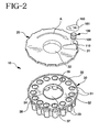
- a pen needle dispenser in accordance with the subject invention is identified generally by the numeral 10 in Figs. 2, 3 and 5.
- pen needle dispenser 10 includes a cover 20 and a container 30.
- Container 30 includes a plurality of cavities 31 about the circumference of container 30, with each cavity 31 being dimensioned to receive a pen needle assembly 100.
- Each pen needle assembly 100 is originally sealed in a respective cavity 31 using a label or sterility barrier 150 that is attached to an upper surface 32 of container 30, which provides sterility for the unused pen needle assemblies 100 contained in each cavity 31.
- Pen needle dispenser 10 is initially loaded with a predetermined number of pen needle assemblies 100 in respective cavities 31, with each cavity 31 being sealed by a label or sterility membrane 150 having a number 151 thereon. Number 151 or other indicia on label 150 indicates to the user how many unused pen needle assemblies 100 remain in pen needle dispenser 10.
- An alternative design according to the present invention includes a label or sterility barrier 150 that does not need to be removed from upper surface 32 of container 30. That type of label 150 would be scored at the location of cavity 31, of course, without affecting the integrity of the seal and would allow for controlled breaking with the distal end of the medication delivery pen. The controlled breaking of the scored area would then allow the distal end of the medication delivery pen to be inserted through label 150 and into hub 102 on pen needle assembly 100 and threaded or snapped thereon.
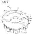
- Fig. 3 is a perspective view of pen needle dispenser 1 fully assembled with cover 20 rotatably mounted on container 30 and label 150 attached to upper surface 32 over one of cavities 31.
- Fig. 3 also shows arrow "A" that indicates the direction a user should rotate cover 20 with respect to container 30 to move slot 21 over the next cavity 31.
- container 30 includes a central opening 37 that is surrounded by an internal flange including an upper internal flange 34 and a lower internal flange 35 and an outer lip 38 around its outer circumference.
- Outer lip 38 includes a plurality of ratchet teeth 33 extending outwardly therefrom and an end of travel lock pin 36 extending from outer lip 38 in the direction of central opening 37.
- End of travel lock pin 36 is positioned on the opposite side of outer lip 38 from one of the ratchet teeth 33 and works with a similar end of travel lock key 26 located on the underside of cover 20 to stop rotation of cover 20 on container 30 when all cavities have passed under slot 21.
- Cover 20 also includes a central opening 22 surrounded by an internal sleeve 23 that is connected to a plurality of retaining tabs 24.
- cover 20 includes an outer lip 27 around its circumference and a plurality of ratchet teeth 25 extending from outer lip 27 in the direction of central opening 22.
- cover 20 is rotatably attached to container 30 by inserting internal sleeve 23 through central opening 37 in container 30 until retaining tabs 24 snap over lower internal flange 35.
- cover 20 is attached to container 30 such that internal sleeve 23 rotates within upper and lower internal flanges 34 and 35.
- upper internal flange 34 and outer lip 38 provide internal support for cover 20, which travels thereon during its rotation on container 30.
- cover 20 When cover 20 is attached to container 30, ratchet teeth 33 extending from container 30 engage with ratchet teeth 25 extending into cover 20 and only permit cover 20 to rotate in the direction of arrow "A" or a clockwise direction. Therefore, cover 20 is not permitted to rotate in the counterclockwise direction or to move slot 21 back over cavities 31 containing used unshielded pen needles 100.
- cover 20 when cover 20 is attached to container 30 it is important to locate end of travel lock key 26 on cover 20 adjacent to end of travel lock pin 36 on container 30, such that cover 20 can proceed with a full clockwise rotation on container 30. Therefore, when all cavities have been accessed using slot 21 on cover 20 and cover 20 has completed a complete clockwise rotation on container 30, end of travel lock key 26 on cover 20 will again be adjacent to end of travel lock pin 36 on container 30 but now will prevent further rotation in the clockwise direction, shown by arrow "A". In the current embodiment, cover 20 can never be rotated in the counterclockwise direction on container 30 because of the above-described interaction of ratchet teeth 25 and 33.
- container 30 includes a plurality of cavities 31 around its circumference that are dimensioned to receive pen needle assemblies 100 with or without shields 110, shown in Fig. 2.
- each cavity 31 includes a tapered opening 39 that guides the distal end of the medication delivery pen into cavity 31 for mating with pen needle assembly 100.
- Each cavity 31 also includes a bottom section 41 and an upper section 42, wherein bottom section 41 has a smaller diameter than upper section 42 with a shelf 43 formed where sections 41 and 42 meet.
- Upper section 42 includes a locking ring 48 and a plurality of laterally extending splines 44 therein that mate with a plurality of outer channels 108 on pen needle assembly 100, described further below.
- Bottom section 41 includes a closed bottom end 45 having a central recess 46 that forms an inner bottom surface 47 in bottom section 41.
- pen needle assembly 100 includes a skirt 101 having an open proximal end 109 and a distal end 107 having a hub 102 extending therefrom.
- a needle cannula 103 is mounted within hub 102 and includes a distal point 104 and a proximal point 105, wherein proximal point 105 is within skirt 101 and distal point 104 extends out of hub 102.
- Skirt 101 also includes a locking flange 106 extending from open proximal end 109.
- Pen needle assembly 100 also includes a plurality of tabs 102a extending from hub 102 that are dimensioned to be received within an open end 112 of a shield 110 when pen needle assembly 100 is originally assembled and loaded into pen needle dispenser 10, as shown in Fig. 6.
- Shield 110 also includes a closed distal end 111 that interacts with inner bottom surface 47 of cavity 31 to prevent pen needle assembly 100 from locking in cavity 31, as described below.
- splines 44 in upper section 42 of cavity 31 engage respective outer channels 108 on skirt 101 of pen needle assembly 100 to prevent rotation of pen needle assembly 100 in cavity 31, which is important if pen needle assembly 100 is of the type having threads within skirt 101 that mate with threads on the distal end of the medication delivery pen.
- pen needle assembly 100 is of the type having a snap attachment
- closed distal end 111 of shield 110 would prevent pen needle assembly 100 from moving into the locked position and locking in cavity 31 when the distal end of a medication delivery pen is snapped into skirt 101.
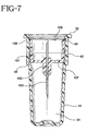
- the used and unshielded pen needle assembly 100 on medication delivery pen is inserted into tapered opening 39 of cavity 31 until distal end 107 of pen needle assembly 100 comes into contact with shelf 43 within cavity 31, the locked position, as shown in Fig. 7.
- locking flange 106 at the open proximal end 109 of skirt 101 has engaged locking ring 48 within cavity 31, which locks pen needle assembly 100 in cavity 31.
- the medication delivery pen can be extracted from skirt 101 by unthreading or unsnapping pen needle assembly 100 from the distal end of the medication delivery pen.
- the user rotates cover 20 in the direction of arrow "A" until slot 21 is aligned with the next cavity 31 having a unused shielded pen needle 100 covered by another label 150.
- ratchet teeth 25 travel over one set of ratchet teeth 33 on container 30, which then prevents cover 20 from rotating in the direction counter to arrow "A".
- an alternative to the uni-directional cover shown in the drawings and described above would be a design that allows the user to rotate back to previously used needles. In that case, the other various features of the present invention could still be used on such a device.
- the current design would allow the user to repeatedly rotate cover 20 in the direction of arrow "A" to each cavity 31 until all of the pen needle assemblies 100 have been used and the last cavity 31 has been encountered by slot 21 on cover 20.
- That last cavity could be left empty so that the user will know that all pen needle assemblies 100 have been used and thereby indicate that pen needle dispenser 10 should now be properly disposed of.
- all the used pen needle assemblies 100 and their proximal points 105 would be protected from accidental needle sticks, since cover 20 would no longer be able to rotate in either direction. As explained above, further rotation in the direction of arrow "A" would be prevented by interaction between end of travel lock pin 36 on container 30 and end of travel lock key 26 on cover 20.
Description
- The subject invention relates to a pen needle dispenser and, more particularly, to an apparatus that holds and dispenses sterile pen needles for medication delivery pens and that safely stores the needles after use.
- Hypodermic syringes are used to deliver selected doses of medication to patients. The prior art hypodermic syringe includes a syringe barrel having opposed proximal and distal ends. A cylindrical chamber wall extends between the ends and defines a fluid receiving chamber. The proximal end of the prior art syringe barrel is substantially open and receives a plunger in sliding fluid tight engagement. The distal end of the prior art syringe barrel includes a passage communicating with the chamber. A needle cannula is mounted to the distal end of the prior art syringe barrel, such that the lumen of the needle cannula communicates with the passage and the chamber of the syringe barrel. Movement of the plunger in a proximal direction draws fluid through the lumen of the needle cannula and into the chamber. Movement of the plunger in a proximal-to-distal direction urges fluid from the chamber and through the lumen of the needle cannula.
- Medication to be injected with the prior art hypodermic syringe often is stored in a vial having a pierceable elastomeric seal. Medication in the prior art vial is accessed by piercing the elastomeric seal with the needle cannula. A selected dose of the medication is drawn into the chamber of the syringe barrel by moving the plunger a selected distance in a proximal direction. The needle cannula is withdrawn from the vial, and the medication is injected into a patient by moving the plunger in a distal direction.
- Some medication, such as insulin is self-administered. The typical diabetes patient will require injections of insulin several times during the course of the day. The required dose of insulin will vary from patient to patient, and for each patient may vary during the course of the day and from day to day. Each diabetes patient will establish a regimen that is appropriate for his or her own medical condition and for his or her lifestyle. The regimen typically includes some combination of a slow or medium acting insulin and a faster acting insulin. Each of these regimens may require the diabetes patient to periodically self-administer insulin in public locations, such as places of employment or restaurants. The required manipulation of the standard prior art hypodermic syringe and vial can be inconvenient and embarrassing in these public environments.
- Medication delivery pens have been developed to facilitate the self-administration of medication. A prior art medication delivery pen is identified generally by the
numeral 1 in Fig. 1. Pen 1 contains a cartridge with sufficient medication for several doses. The prior art cartridge has opposed proximal and distal ends. The distal end is closed by a pierceable and resealable rubber septum identified by thenumeral 2 in Fig. 1. The proximal end receives a stopper in sliding fluid-tight engagement. The prior art cartridge is disposed in an elongate pen-like body 4 with a proximal end (not shown) and an opposeddistal end 6. The proximal end of the pen body includes a plunger for selectively driving the stopper of the cartridge in the distal direction and a dose setting mechanism for determining the distance through which the plunger and stopper can move.Distal end 6 ofpen body 4 includes an array ofthreads 8 for threaded engagement with apen needle assembly 90.Pen needle assembly 90 includes aneedle cannula 91 with opposed proximal anddistal points mounting skirt 94 which surrounds theproximal tip 92.Mounting skirt 94 is threadedly engageable withthreads 8 ondistal end 6 ofpen body 4. Asafety shield 95 is releasably engaged overdistal point 93 and portions ofmounting skirt 94 to prevent accidental needle sticks. - A person who must periodically inject doses of medication will carry a
medication delivery pen 1 and a supply ofpen needle assemblies 90. Eachpen needle assembly 90 has itsneedle cannula 91 safely and sterility sealed in itsown shield 95, and is accessed immediately prior to administering a dose of medication.Pen needle assembly 90 then is mounted todistal end 6 ofprior art pen 1. This mounting causesproximal point 92 ofneedle cannula 91 to piercerubber septum 2 of the cartridge, to placeneedle cannula 91 in communication with the medication inpen 1.Pen 1 then is used to inject the selected dose of medication. After completing the injection,needle assembly 90 is separated frompen 1 and is discarded.Pen 1 may be used repeatedly in this manner until the medication is exhausted. Such prior art pens offer many conveniences and efficiencies. However, the storage of unused needles and the final disposal of used needles has presented problems. In particular, supplies of new needles often are loosely scattered in the bottom of purses ur briefcases, and used needles are often disposed of unsafely. - US 5,590,774 describes a surgical needle discard container which includes a plurality of needle receiving compartments defined therein. A lid is rotatably attached to one end of the container to block access to compartments not in use. An aperture defined in the lid provides access to one of the compartments. The aperture is selectively aligned with each compartment as the lid is rotated relative to the container by an advancing mechanism. A cutting device associated with the lid and container severs the portion of a suture that extends beyond the end of the container from a needle disposed in one of the compartments by rotating the lid relative to the container.
- According to the present invention, there is provided an apparatus for storing a plurality of needle assemblies and for selectively dispensing said needle assemblies therefrom, said apparatus comprising:
- a container having an upper surface including a plurality of cavities, wherein each cavity is dimensioned to receive a needle assembly;
- a plurality of needle assembles, each needle assembly being received in a respective one of the plurality of cavities; and
- a cover rotatably mounted on said container, said cover having a slot that can be rotated into alignment with one of said plurality of cavities in said container to provide access through said cover to a needle assembly located in said one of said plurality of cavities; characterised by
- a recess extending into said bottom end of said lower section to provide a raised bottom surface in said bottom end; and
- a shield having a closed distal end and an open proximal end that is mounted on said hub of said needle assembly such that, when said shield is mounted on said hub and said shielded needle assembly is inserted into said cavity, interaction between said closed distal end of said shield and said raised bottom surface of said recess in said cavity prevent said needle assembly from moving into the locked position in said cavity; and
- means for locking said needle assembly in said cavity in the locked position
- when said shield is not mounted on said hub; and wherein
- said cavity further comprises an upper section and a lower section having a smaller diameter than said upper section and a shelf located where said upper section is connected to said lower section, said lower section having a bottom end;
- said needle assembly includes a skirt having an open proximal end and a distal end that is connected to a hub with a double-ended needle cannula extending through said hub.
-
- The subject of the invention relates to a storing and dispensing apparatus for needle assemblies used with hypodermic syringes and preferably pen needles used with medication delivery pens.
- The pen needle dispenser of the present invention includes a cover rotatably mounted on a container having a plurality of cavities, with each cavity dimensioned to receive a pen needle assembly with or without a shield. The cover includes a slot therethrough that is rotated into alignment with a cavity in the container that contains an unused shielded pen needle. When the slot is aligned with such a cavity, the user. inserts the distal end of a medication delivery pen into the cavity to mount the unused shielded pen needle on the medication delivery pen. After the shield has been removed from the pen needle and the injection has been performed, the used unshielded pen needle is returned to the cavity using the medication delivery pen and is snap-locked in the cavity to allow the pen needle to be easily removed from the distal end of the medication delivery pen and prevent reuse of the pen needle. The user then rotates the cover until the slot in the cover provides access to the next cavity containing another unused shielded pen needle to be used during the next injection.
- As noted above, one object of the present invention is to prevent the pen needle from being reused by having it locked and covered in the pen needle dispenser. In addition, once the cover has been rotated to the next cavity, the pen needle dispenser provides means to prevent the cover from rotating back to used pen needles.
- Another object of the present invention is to provide a user with a convenient way to carry, dispose of and keep track of their personal pen needle usage. The pen needle dispenser will contain a predetermined number of pen needles in respective cavities, with each cavity being sealed by a numbered label or sterility membrane. The numbered labels will indicate how many unused pen needles remain in the pen needle dispenser.
- Another object of the present invention is to provide a pen needle dispenser that can hold and dispense pen needles of different types that are, e.g., threaded or snapped onto the distal end of a medication delivery pen. By working with snap-on designed needles, the pen needle dispenser allows for a very simple push-pull motion to be used to attach and detach the pen needle assembly from the medication delivery pen.
- Another object of the present invention is to allow the user to carry pen needle assemblies in one convenient dispensing mechanism and provide the user with a convenient and safe way to dispose of these used pen needle assemblies.
- These and other aspects, features and advantages of the present invention will become apparent from the following detailed description taken in conjunction with the accompanying drawings.
-
- Fig. I is an exploded perspective view of a prior art pen needle and the distal end of a prior art medication delivery pen with which the present invention is intended to be used;
- Fig. 2 is an exploded perspective view of a pen needle dispenser according to the present invention;
- Fig. 3 is a perspective view of an assembled pen needle dispenser shown in Fig. 2;
- Fig. 4 is a perspective view of the underside of the cover of the pen needle dispenser shown in Fig. 2;
- Fig. 5 is a cross-sectional view of the assembled pen needle dispenser shown in Fig. 3;
- Fig. 6 is a cross-sectional view of a cavity containing an unused shielded pen needle in the pen needle dispenser shown in Fig. 2; and
- Fig. 7 is a cross-sectional view of another cavity containing a used unshielded pen needle locked in the pen needle dispenser shown in Fig. 2.
-
- A pen needle dispenser in accordance with the subject invention is identified generally by the numeral 10 in Figs. 2, 3 and 5. As shown in the exploded perspective view in Fig. 2,
pen needle dispenser 10 includes acover 20 and acontainer 30.Container 30 includes a plurality ofcavities 31 about the circumference ofcontainer 30, with eachcavity 31 being dimensioned to receive apen needle assembly 100. Eachpen needle assembly 100 is originally sealed in arespective cavity 31 using a label orsterility barrier 150 that is attached to anupper surface 32 ofcontainer 30, which provides sterility for the unusedpen needle assemblies 100 contained in eachcavity 31.Pen needle dispenser 10 is initially loaded with a predetermined number ofpen needle assemblies 100 inrespective cavities 31, with eachcavity 31 being sealed by a label orsterility membrane 150 having anumber 151 thereon.Number 151 or other indicia onlabel 150 indicates to the user how many unusedpen needle assemblies 100 remain inpen needle dispenser 10. - An alternative design according to the present invention includes a label or
sterility barrier 150 that does not need to be removed fromupper surface 32 ofcontainer 30. That type oflabel 150 would be scored at the location ofcavity 31, of course, without affecting the integrity of the seal and would allow for controlled breaking with the distal end of the medication delivery pen. The controlled breaking of the scored area would then allow the distal end of the medication delivery pen to be inserted throughlabel 150 and intohub 102 onpen needle assembly 100 and threaded or snapped thereon. - Fig. 3 is a perspective view of
pen needle dispenser 1 fully assembled withcover 20 rotatably mounted oncontainer 30 andlabel 150 attached toupper surface 32 over one ofcavities 31. Fig. 3 also shows arrow "A" that indicates the direction a user should rotate cover 20 with respect tocontainer 30 to moveslot 21 over thenext cavity 31. As more clearly shown in Figs. 2, 4 and 5,container 30 includes acentral opening 37 that is surrounded by an internal flange including an upperinternal flange 34 and a lowerinternal flange 35 and anouter lip 38 around its outer circumference.Outer lip 38 includes a plurality ofratchet teeth 33 extending outwardly therefrom and an end oftravel lock pin 36 extending fromouter lip 38 in the direction ofcentral opening 37. End oftravel lock pin 36 is positioned on the opposite side ofouter lip 38 from one of theratchet teeth 33 and works with a similar end of travel lock key 26 located on the underside ofcover 20 to stop rotation ofcover 20 oncontainer 30 when all cavities have passed underslot 21. -
Cover 20 also includes acentral opening 22 surrounded by aninternal sleeve 23 that is connected to a plurality of retainingtabs 24. In addition, cover 20 includes anouter lip 27 around its circumference and a plurality ofratchet teeth 25 extending fromouter lip 27 in the direction ofcentral opening 22. As shown in Fig. 5, cover 20 is rotatably attached tocontainer 30 by insertinginternal sleeve 23 throughcentral opening 37 incontainer 30 until retainingtabs 24 snap over lowerinternal flange 35. In the assembled arrangement shown in Fig. 5, when retainingtabs 24 snap over lowerinternal flange 35, cover 20 is attached tocontainer 30 such thatinternal sleeve 23 rotates within upper and lowerinternal flanges internal flange 34 andouter lip 38 provide internal support forcover 20, which travels thereon during its rotation oncontainer 30. Whencover 20 is attached tocontainer 30, ratchetteeth 33 extending fromcontainer 30 engage withratchet teeth 25 extending intocover 20 and only permitcover 20 to rotate in the direction of arrow "A" or a clockwise direction. Therefore, cover 20 is not permitted to rotate in the counterclockwise direction or to moveslot 21 back overcavities 31 containing used unshielded pen needles 100. - Of course, when
cover 20 is attached tocontainer 30 it is important to locate end oftravel lock key 26 oncover 20 adjacent to end oftravel lock pin 36 oncontainer 30, such thatcover 20 can proceed with a full clockwise rotation oncontainer 30. Therefore, when all cavities have been accessed usingslot 21 oncover 20 and cover 20 has completed a complete clockwise rotation oncontainer 30, end oftravel lock key 26 oncover 20 will again be adjacent to end oftravel lock pin 36 oncontainer 30 but now will prevent further rotation in the clockwise direction, shown by arrow "A". In the current embodiment, cover 20 can never be rotated in the counterclockwise direction oncontainer 30 because of the above-described interaction ofratchet teeth - As described above,
container 30 includes a plurality ofcavities 31 around its circumference that are dimensioned to receivepen needle assemblies 100 with or withoutshields 110, shown in Fig. 2. As shown in Fig. 6, eachcavity 31 includes a taperedopening 39 that guides the distal end of the medication delivery pen intocavity 31 for mating withpen needle assembly 100. Eachcavity 31 also includes abottom section 41 and anupper section 42, whereinbottom section 41 has a smaller diameter thanupper section 42 with ashelf 43 formed wheresections Upper section 42 includes a lockingring 48 and a plurality of laterally extendingsplines 44 therein that mate with a plurality ofouter channels 108 onpen needle assembly 100, described further below.Bottom section 41 includes a closedbottom end 45 having acentral recess 46 that forms aninner bottom surface 47 inbottom section 41. - As shown in Figs. 6 and 7,
pen needle assembly 100 includes askirt 101 having an openproximal end 109 and adistal end 107 having ahub 102 extending therefrom. Aneedle cannula 103 is mounted withinhub 102 and includes adistal point 104 and aproximal point 105, whereinproximal point 105 is withinskirt 101 anddistal point 104 extends out ofhub 102.Skirt 101 also includes a lockingflange 106 extending from openproximal end 109.Pen needle assembly 100 also includes a plurality oftabs 102a extending fromhub 102 that are dimensioned to be received within anopen end 112 of ashield 110 whenpen needle assembly 100 is originally assembled and loaded intopen needle dispenser 10, as shown in Fig. 6.Shield 110 also includes a closeddistal end 111 that interacts withinner bottom surface 47 ofcavity 31 to preventpen needle assembly 100 from locking incavity 31, as described below. - After
shield 110 has been mounted onpen needle assembly 100 the assembled unit is inserted intocavity 31 untildistal end 111 ofshield 110 is stopped byinner bottom surface 47 on the inside ofrecess 46 atbottom end 45 ofcavity 31. As shown in Fig. 6, in this arrangement,pen needle assembly 100 with attachedshield 110 is slideably received withcavity 31 and can be easily removed since it is not locked or permanently retained therein except by label orsterility barrier 150, shown in Fig. 3, which is removed beforepen needle assembly 100 is mounted on the medication delivery pen. In this arrangement, splines 44 inupper section 42 ofcavity 31 engage respectiveouter channels 108 onskirt 101 ofpen needle assembly 100 to prevent rotation ofpen needle assembly 100 incavity 31, which is important ifpen needle assembly 100 is of the type having threads withinskirt 101 that mate with threads on the distal end of the medication delivery pen. Of course, if thepen needle assembly 100 is of the type having a snap attachment, closeddistal end 111 ofshield 110 would preventpen needle assembly 100 from moving into the locked position and locking incavity 31 when the distal end of a medication delivery pen is snapped intoskirt 101. - After use, the used and unshielded
pen needle assembly 100 on medication delivery pen is inserted into taperedopening 39 ofcavity 31 untildistal end 107 ofpen needle assembly 100 comes into contact withshelf 43 withincavity 31, the locked position, as shown in Fig. 7. In that position, lockingflange 106 at the openproximal end 109 ofskirt 101 has engaged lockingring 48 withincavity 31, which lockspen needle assembly 100 incavity 31. At this point, the medication delivery pen can be extracted fromskirt 101 by unthreading or unsnappingpen needle assembly 100 from the distal end of the medication delivery pen. Then, the user rotatescover 20 in the direction of arrow "A" untilslot 21 is aligned with thenext cavity 31 having a unused shieldedpen needle 100 covered by anotherlabel 150. - As
cover 20 is rotated in the direction of arrow "A"ratchet teeth 25 travel over one set ofratchet teeth 33 oncontainer 30, which then prevents cover 20 from rotating in the direction counter to arrow "A". Of course, an alternative to the uni-directional cover shown in the drawings and described above would be a design that allows the user to rotate back to previously used needles. In that case, the other various features of the present invention could still be used on such a device. However, as described above and shown in the drawings, the current design would allow the user to repeatedly rotatecover 20 in the direction of arrow "A" to eachcavity 31 until all of thepen needle assemblies 100 have been used and thelast cavity 31 has been encountered byslot 21 oncover 20. That last cavity could be left empty so that the user will know that allpen needle assemblies 100 have been used and thereby indicate thatpen needle dispenser 10 should now be properly disposed of. In addition, by providing anempty cavity 31 with all filledcavities 31 being fully enclosed behindcover 20, all the usedpen needle assemblies 100 and theirproximal points 105 would be protected from accidental needle sticks, sincecover 20 would no longer be able to rotate in either direction. As explained above, further rotation in the direction of arrow "A" would be prevented by interaction between end oftravel lock pin 36 oncontainer 30 and end oftravel lock key 26 oncover 20. - While the invention has been described with respect to a preferred embodiment, it is apparent that various changes can be made without departing from the scope of the invention as defined by the appended claims.
means preventing said needle assembly from moving into a locked position in said cavity which includes:
Claims (8)
- An apparatus (10) for storing a plurality of needle assemblies (100) and for selectively dispensing said needle assemblies therefrom, said apparatus comprising:characterised bya container (30) having an upper surface including a plurality of cavities (31), wherein each cavity (31) is dimensioned to receive a needle assembly (100);a plurality of needle assembles (100), each needle assembly (100) being received in a respective one of the plurality of cavities (31); anda cover (20) rotatably mounted on said container (30), said cover (20) having a slot (21) that can be rotated into alignment with one of said plurality of cavities (31) in said container (30) to provide access through said cover (20) to a needle assembly (100) located in said one of said plurality of cavities (31);
means (46, 110) preventing said needle assembly (100) from moving into a locked position in said cavity (31) which includes:a recess (46) extending into said bottom end (45) of said lower section (41) to provide a raised bottom surface (47) in said bottom end (45);a shield (110) having a closed distal end (111) and an open proximal end that is mounted on said hub (102) of said needle assembly (100) such that, when said shield (110) is mounted on said hub (102) and said shielded needle assembly (100) is inserted into said cavity (31), interaction between said closed distal end (111) of said shield (110) and said raised bottom surface (47) of said recess (46) in said cavity (31) prevents said needle assembly (100) from moving into the locked position in said cavity (31);and means for locking said needle assembly (100) in said cavity (31) in the locked position when said shield is not mounted on said hub; and whereinsaid cavity (31) further comprises an upper section (42) and a lower section (41) having a smaller diameter than said upper section (42) and a shelf (43) located where said upper section (42) is connected to said lower section (41), said lower section (41) having a bottom end (45);said needle assembly (100) includes a skirt (101) having an open proximal end (101) and a distal end (107) that is connected to a hub (102) with a double-ended needle cannula extending through said hub. - An apparatus according to Claim 1, further comprising means (25, 33) for preventing said cover (20) from rotating on said container (30) in a reverse direction while permitting said cover (20) to rotate on said container (30) in a forward direction to rotate said slot (21) into alignment with one of said plurality of cavities (31) in said container (30).
- An apparatus according to Claim 2, further comprises means (26, 36) for preventing said cover (20) from further rotation in said forward direction after said slot (20) has been rotated into alignment with each of said plurality of cavities (31) in said container (30).
- An apparatus according to Claim 1, wherein said upper section (42) of said cavity (31) further comprises a plurality of splines (44) and said skirt (101) of said needle assembly (100) includes a plurality of outer channels (108) that mate with said plurality of splines (44) in said cavity (31) to prevent said needle assembly (100) from rotating within said cavity (31) so that said needle assembly (100) in said cavity (31) can be threaded onto a medication delivery pen.
- An apparatus according to Claim 1, wherein:said upper section (42) of said cavity (31) has a tapered opening; andsaid means (46, 110) for locking said needle assembly in said cavity (31) in the locked position includes:a locking ring (48) within said tapered opening of said cavity (31); anda locking flange (106) around said open proximal end of said skirt (101) of said needle assembly (100) that snaps over said locking ring (48) to lock said needle assembly (100) in said locked position.
- An apparatus according to Claim 5, wherein said distal end of said skirt (101) of said needle assembly (100) contacts said shelf (43) between said upper and lower sections (42, 41) in said cavity (31) when said needle assembly (100) is locked in said locked position.
- An apparatus according to Claim 1, further comprising a sterility barrier (150) over each of said plurality of cavities (31); and further wherein said sterility barrier (150) includes a plurality of removable labels with each of said removable labels covering one of said plurality of cavities.
- An apparatus according to Claim 1, further comprising a sterility barrier (150) over each of said plurality of cavities (31); and further wherein said sterility barrier (150) includes scoring over each of said plurality of cavities (31) to permit said sterility barrier (150) to be pierced by the medication delivery pen accessing said cavity (30) behind said scoring.
Applications Claiming Priority (2)
| Application Number | Priority Date | Filing Date | Title |
|---|---|---|---|
| US08/928,691 US5873462A (en) | 1997-09-12 | 1997-09-12 | Pen needle dispenser |
| US928691 | 1997-09-12 |
Publications (3)
| Publication Number | Publication Date |
|---|---|
| EP0903154A2 EP0903154A2 (en) | 1999-03-24 |
| EP0903154A3 EP0903154A3 (en) | 1999-04-21 |
| EP0903154B1 true EP0903154B1 (en) | 2002-12-18 |
Family
ID=25456610
Family Applications (1)
| Application Number | Title | Priority Date | Filing Date |
|---|---|---|---|
| EP98307080A Expired - Lifetime EP0903154B1 (en) | 1997-09-12 | 1998-09-03 | Pen needle dispenser |
Country Status (5)
| Country | Link |
|---|---|
| US (1) | US5873462A (en) |
| EP (1) | EP0903154B1 (en) |
| JP (1) | JP4176204B2 (en) |
| CA (1) | CA2244966C (en) |
| DE (1) | DE69810219T2 (en) |
Cited By (1)
| Publication number | Priority date | Publication date | Assignee | Title |
|---|---|---|---|---|
| WO2019210126A1 (en) | 2018-04-27 | 2019-10-31 | Becton, Dickinson And Company | Pen needle storage |
Families Citing this family (78)
| Publication number | Priority date | Publication date | Assignee | Title |
|---|---|---|---|---|
| EP1289585B1 (en) * | 2000-05-15 | 2007-04-25 | Ares Trading S.A. | Device for separating the connecting end of a hypodermic needle from the tip of an injection instrument |
| US6547764B2 (en) * | 2000-05-31 | 2003-04-15 | Novo Nordisk A/S | Double pointed injection needle |
| ES2605353T3 (en) | 2000-08-02 | 2017-03-14 | Becton, Dickinson And Company | Pen needle system and safety shield |
| US6986760B2 (en) * | 2000-08-02 | 2006-01-17 | Becton, Dickinson And Company | Pen needle and safety shield system |
| EP1307252A1 (en) | 2000-08-03 | 2003-05-07 | Novo Nordisk A/S | A needle magazine |
| AU2001272374A1 (en) * | 2000-08-03 | 2002-02-18 | Novo-Nordisk A/S | A needle magazine |
| US20020050463A1 (en) * | 2000-09-22 | 2002-05-02 | Mcdowell Christopher | Tray for surgical fastners |
| US6387078B1 (en) * | 2000-12-21 | 2002-05-14 | Gillespie, Iii Richard D. | Automatic mixing and injecting apparatus |
| ES2257597T3 (en) * | 2001-11-30 | 2006-08-01 | Novo Nordisk A/S | SAFETY NEEDLE ASSEMBLY. |
| DE10203598A1 (en) * | 2002-01-30 | 2003-08-07 | Disetronic Licensing Ag | Injection device with sterile mounted injection needle as well as needle carrier and ampoule for such an injection device |
| FI117689B (en) * | 2002-08-21 | 2007-01-31 | Addoz Oy | Device for dispensing in desired doses of drugs in the form of pills or capsules |
| US8932264B2 (en) * | 2003-08-11 | 2015-01-13 | Becton, Dickinson And Company | Medication delivery pen assembly with needle locking safety shield |
| GB2408255A (en) * | 2003-11-18 | 2005-05-25 | Stephen Frederick Marston | Container system for hypodermic needle packs for insulin injection |
| US7604118B2 (en) * | 2003-12-15 | 2009-10-20 | Panasonic Corporation | Puncture needle cartridge and lancet for blood collection |
| EP1732627B1 (en) | 2004-03-31 | 2010-05-19 | Eli Lilly And Company | Injection apparatus having a needle cassette for delivering a pharmaceutical liquid |
| BRPI0518960A2 (en) * | 2004-12-09 | 2008-12-16 | West Pharm Serv Inc | breech-loaded fixed needle syringe and automatic injection device having the same |
| US7234602B2 (en) * | 2005-02-08 | 2007-06-26 | Damian Roberti | Apparatus for holding and organizing artist supplies |
| US20060175330A1 (en) * | 2005-02-09 | 2006-08-10 | Oxygen Development, Llc | Enhanced liquid container |
| EP1904125B1 (en) * | 2005-07-18 | 2018-10-17 | West Pharmaceutical Services, Inc. | Auto-injection syringe having vent device |
| US7988675B2 (en) * | 2005-12-08 | 2011-08-02 | West Pharmaceutical Services Of Delaware, Inc. | Automatic injection and retraction devices for use with pre-filled syringe cartridges |
| GB0609782D0 (en) * | 2006-05-16 | 2006-06-28 | Clini Cal Design Technologies | Container system for hypodermic needles |
| US9358348B2 (en) * | 2006-06-14 | 2016-06-07 | Covidien Lp | Safety shield for medical needles |
| US8083098B1 (en) * | 2007-02-22 | 2011-12-27 | Michael Schaffer | Storage and dispensing system for needle-shields |
| CA2682328A1 (en) * | 2007-05-30 | 2008-12-11 | Eli Lilly And Company | Cartridge with multiple injection needles for a medication injection device |
| CN101854969B (en) * | 2007-07-28 | 2013-04-03 | 诺沃-诺迪斯克有限公司 | A needle magazine |
| CA2639320C (en) * | 2007-09-07 | 2016-10-25 | Becton, Dickinson And Company | Pen-needle assembly for preventing under-torquing and over-torquing of pen-needle |
| US8241257B2 (en) * | 2008-01-15 | 2012-08-14 | Becton, Dickinson And Company | Pen needle assembly |
| WO2010048752A1 (en) * | 2008-10-29 | 2010-05-06 | Pan Qiubao | Needle-replacing apparatus mating with split-type continuous injector |
| US20110060292A1 (en) * | 2009-08-14 | 2011-03-10 | Stat Medical Devices, Inc. | Pen needle storage device with integral removal and/or installation system |
| US20110071475A1 (en) | 2009-09-18 | 2011-03-24 | Becton, Dickinson And Company | Outer cover of a pen needle for a drug delivery pen |
| GB0916909D0 (en) * | 2009-09-25 | 2009-11-11 | Exchange Supplies Ltd | Container for disposal of syringe needles |
| US9566128B2 (en) * | 2009-09-30 | 2017-02-14 | Ultimed Inc. | Shipping and aggregation system for medical sharps |
| US9016472B2 (en) | 2010-03-05 | 2015-04-28 | Novo Nordisk A/S | Two-part hinged needle magazine |
| US20110233088A1 (en) * | 2010-03-26 | 2011-09-29 | Bartee Barry K | Surgical container |
| US8887912B2 (en) * | 2010-08-16 | 2014-11-18 | Becton, Dickinson And Company | Living hinge needle assembly for medicament delivery device |
| US9107988B2 (en) * | 2010-08-16 | 2015-08-18 | Becton, Dickinson And Company | Circuitous band needle changing apparatus |
| US9216253B2 (en) * | 2010-08-16 | 2015-12-22 | Becton, Dickinson And Company | Needle dispensing and storing apparatus for medicament delivery device |
| US9381303B2 (en) * | 2010-08-16 | 2016-07-05 | Becton, Dickinson And Company | Sterility barrier for pen needle and storage container therefor |
| US9101724B2 (en) | 2010-08-16 | 2015-08-11 | Becton, Dickinson And Company | Pen injection device needle dispensing and storing apparatus |
| US8919555B2 (en) | 2010-09-01 | 2014-12-30 | Sambhu N. Choudhury | Medical sharps storage device and method of using the same |
| EP2455117A1 (en) * | 2010-11-19 | 2012-05-23 | Sanofi-Aventis Deutschland GmbH | Assembly device for injection needles |
| AU2011329876B2 (en) * | 2010-11-19 | 2014-09-18 | Eli Lilly And Company | Needle magazine for medication injection device |
| CN103492279A (en) * | 2010-12-22 | 2014-01-01 | 高露洁-棕榄公司 | Package of oral care implements and method of using the same |
| EP2500053A1 (en) * | 2011-03-15 | 2012-09-19 | Sanofi-Aventis Deutschland GmbH | Needle assembly storage device |
| EP2510959A1 (en) * | 2011-04-13 | 2012-10-17 | Sanofi-Aventis Deutschland GmbH | Needle assembly storage device |
| EP2517744A1 (en) * | 2011-04-29 | 2012-10-31 | Sanofi-Aventis Deutschland GmbH | Needle assembly reuse prevention mechanism |
| EP2522378A1 (en) * | 2011-05-11 | 2012-11-14 | Sanofi-Aventis Deutschland GmbH | Needle assembly storage device |
| EP2522379A1 (en) * | 2011-05-12 | 2012-11-14 | Sanofi-Aventis Deutschland GmbH | Needle assembly storage device |
| EP2913078B1 (en) | 2011-06-08 | 2020-01-22 | Becton, Dickinson and Company | Method for separating a metal needle from a needle holder |
| EP2537544A1 (en) | 2011-06-21 | 2012-12-26 | Sanofi-Aventis Deutschland GmbH | Needle assembly storage device |
| EP2586475A1 (en) * | 2011-10-31 | 2013-05-01 | Sanofi-Aventis Deutschland GmbH | Storage device for single-use needle assemblies |
| WO2013122941A1 (en) * | 2012-02-13 | 2013-08-22 | Becton, Dickinson And Company | Medical cannula package |
| EP2732835A1 (en) * | 2012-11-14 | 2014-05-21 | Sanofi-Aventis Deutschland GmbH | Needle assembly magazine |
| EP2829294A1 (en) * | 2013-07-22 | 2015-01-28 | Sanofi-Aventis Deutschland GmbH | Reuse prevention mechanism |
| AU2014409123A1 (en) * | 2013-10-18 | 2016-05-26 | Michael H. SCHAFFER | Sharps end capture device and method |
| US9839489B2 (en) | 2013-10-18 | 2017-12-12 | Starcap Medical, Llc | Sharps end capture device and method |
| US10704944B2 (en) | 2014-09-14 | 2020-07-07 | Becton, Dickinson And Company | System and method for capturing dose information |
| US10971260B2 (en) | 2014-09-14 | 2021-04-06 | Becton, Dickinson And Company | System and method for capturing dose information |
| GB2536412B (en) * | 2015-03-09 | 2021-04-21 | Diabetes Care Tech Ltd | A casing |
| ITUB20152531A1 (en) * | 2015-07-28 | 2017-01-28 | Health Robotics Srl | CONTAINER FOR CLOSING CAPS OF SYRINGES |
| CN113577437B (en) | 2016-04-28 | 2023-04-28 | 恩贝克塔公司 | Needle storage cartridge with status indicator |
| WO2017189174A1 (en) | 2016-04-28 | 2017-11-02 | Becton, Dickinson And Company | Pen needle magazine |
| WO2017189169A1 (en) | 2016-04-28 | 2017-11-02 | Becton, Dickinson And Company | Pen needle exchange system |
| JP6921117B2 (en) | 2016-04-28 | 2021-08-18 | ベクトン・ディキンソン・アンド・カンパニーBecton, Dickinson And Company | Pen Needle Magazine |
| US20190125982A1 (en) * | 2016-04-28 | 2019-05-02 | Becton, Dickinson And Company | Radial needle storage magazine |
| ES2901600T3 (en) | 2016-04-28 | 2022-03-23 | Becton Dickinson Co | pen needle charger |
| WO2017189165A1 (en) | 2016-04-28 | 2017-11-02 | Becton, Dickinson And Company | Pen needle magazine |
| WO2017189164A1 (en) | 2016-04-28 | 2017-11-02 | Becton, Dickinson And Company | Pen needle magazine |
| US11007313B2 (en) | 2016-04-28 | 2021-05-18 | Becton, Dickinson And Company | Pen needle magazine |
| CA3019344A1 (en) | 2016-04-28 | 2017-11-02 | Becton, Dickinson And Company | Pen needle magazine |
| WO2017189168A1 (en) | 2016-04-28 | 2017-11-02 | Becton, Dickinson And Company | Pen needle exchange system |
| KR101678581B1 (en) * | 2016-07-26 | 2016-12-06 | 주식회사 건설방재기술연구원 | Apparatus for detecting crack and reparing to prevent concrete bridge from collapse |
| WO2018050260A1 (en) * | 2016-09-19 | 2018-03-22 | Diabetes Care Technology Limited | A casing |
| WO2019005495A1 (en) | 2017-06-27 | 2019-01-03 | Becton, Dickinson And Company | Pen needle multiple carrier injection system |
| CN107485764B (en) * | 2017-09-19 | 2020-07-31 | 三门县隽斜贸易有限公司 | Be used for clinical metal syringe needle collection device of medical treatment |
| EP3731907A4 (en) * | 2017-12-28 | 2021-09-22 | Becton, Dickinson and Company | Pen needle assembly apparatus |
| CA3089736A1 (en) | 2018-02-01 | 2019-08-08 | Becton, Dickinson And Company | Multiple cavity carrier apparatuses for detecting removal of items from cavities and their replacement |
| EP3781232A4 (en) * | 2018-04-18 | 2022-01-12 | Becton, Dickinson and Company | Pen needle assembly apparatus |
Family Cites Families (6)
| Publication number | Priority date | Publication date | Assignee | Title |
|---|---|---|---|---|
| US3292776A (en) * | 1964-11-12 | 1966-12-20 | Thomas R Penn | Hypodermic storage kit |
| US4555044A (en) * | 1983-08-08 | 1985-11-26 | Pearo John M | Tamper-proof pill dispenser |
| US5154296A (en) * | 1989-05-26 | 1992-10-13 | Ortho Pharmaceutical (Canada) Ltd. | Pill dispenser |
| US5449085A (en) * | 1994-03-14 | 1995-09-12 | Electra Form, Inc. | Recyclable container and rotatable closure of plastics material |
| US5590774A (en) * | 1995-06-06 | 1997-01-07 | Roberts; Holly H. | Surgical needle discard container |
| AUPN540595A0 (en) * | 1995-09-13 | 1995-10-05 | Needle Technology (Aust) Limited | Needle housing |
-
1997
- 1997-09-12 US US08/928,691 patent/US5873462A/en not_active Expired - Lifetime
-
1998
- 1998-08-12 CA CA002244966A patent/CA2244966C/en not_active Expired - Lifetime
- 1998-09-03 DE DE69810219T patent/DE69810219T2/en not_active Expired - Lifetime
- 1998-09-03 EP EP98307080A patent/EP0903154B1/en not_active Expired - Lifetime
- 1998-09-14 JP JP26054398A patent/JP4176204B2/en not_active Expired - Lifetime
Cited By (2)
| Publication number | Priority date | Publication date | Assignee | Title |
|---|---|---|---|---|
| WO2019210126A1 (en) | 2018-04-27 | 2019-10-31 | Becton, Dickinson And Company | Pen needle storage |
| US11717604B2 (en) | 2018-04-27 | 2023-08-08 | Embecta Corp. | Pen needle storage |
Also Published As
| Publication number | Publication date |
|---|---|
| EP0903154A3 (en) | 1999-04-21 |
| EP0903154A2 (en) | 1999-03-24 |
| CA2244966A1 (en) | 1999-03-12 |
| CA2244966C (en) | 2003-11-18 |
| JPH11146912A (en) | 1999-06-02 |
| JP4176204B2 (en) | 2008-11-05 |
| DE69810219D1 (en) | 2003-01-30 |
| US5873462A (en) | 1999-02-23 |
| DE69810219T2 (en) | 2003-08-28 |
Similar Documents
| Publication | Publication Date | Title |
|---|---|---|
| EP0903154B1 (en) | Pen needle dispenser | |
| EP0903155B1 (en) | Dispensing magazine for pen needles | |
| US6346094B2 (en) | Pen needle magazine | |
| JP4184494B2 (en) | Pen needle assembly | |
| US5941857A (en) | Disposable pen needle | |
| EP0688572B1 (en) | Time of last injection indicator for medication delivery pen | |
| US10434243B2 (en) | Living hinge needle assembly for medicament delivery device | |
| EP0697222B1 (en) | Pen needle dispenser | |
| JPH08103496A (en) | Adaptor for dose setting knob of liquid chemical feeding pen |
Legal Events
| Date | Code | Title | Description |
|---|---|---|---|
| PUAI | Public reference made under article 153(3) epc to a published international application that has entered the european phase |
Free format text: ORIGINAL CODE: 0009012 |
|
| PUAL | Search report despatched |
Free format text: ORIGINAL CODE: 0009013 |
|
| AK | Designated contracting states |
Kind code of ref document: A2 Designated state(s): DE FR GB IT |
|
| AX | Request for extension of the european patent |
Free format text: AL;LT;LV;MK;RO;SI |
|
| AK | Designated contracting states |
Kind code of ref document: A3 Designated state(s): AT BE CH CY DE DK ES FI FR GB GR IE IT LI LU MC NL PT SE |
|
| AX | Request for extension of the european patent |
Free format text: AL;LT;LV;MK;RO;SI |
|
| 17P | Request for examination filed |
Effective date: 19991020 |
|
| AKX | Designation fees paid |
Free format text: DE FR GB IT |
|
| 17Q | First examination report despatched |
Effective date: 20010314 |
|
| GRAG | Despatch of communication of intention to grant |
Free format text: ORIGINAL CODE: EPIDOS AGRA |
|
| GRAG | Despatch of communication of intention to grant |
Free format text: ORIGINAL CODE: EPIDOS AGRA |
|
| GRAH | Despatch of communication of intention to grant a patent |
Free format text: ORIGINAL CODE: EPIDOS IGRA |
|
| GRAH | Despatch of communication of intention to grant a patent |
Free format text: ORIGINAL CODE: EPIDOS IGRA |
|
| GRAA | (expected) grant |
Free format text: ORIGINAL CODE: 0009210 |
|
| AK | Designated contracting states |
Kind code of ref document: B1 Designated state(s): DE FR GB IT |
|
| REG | Reference to a national code |
Ref country code: GB Ref legal event code: FG4D |
|
| REF | Corresponds to: |
Ref document number: 69810219 Country of ref document: DE Date of ref document: 20030130 Kind code of ref document: P Ref document number: 69810219 Country of ref document: DE Date of ref document: 20030130 |
|
| ET | Fr: translation filed | ||
| PLBE | No opposition filed within time limit |
Free format text: ORIGINAL CODE: 0009261 |
|
| STAA | Information on the status of an ep patent application or granted ep patent |
Free format text: STATUS: NO OPPOSITION FILED WITHIN TIME LIMIT |
|
| 26N | No opposition filed |
Effective date: 20030919 |
|
| REG | Reference to a national code |
Ref country code: FR Ref legal event code: PLFP Year of fee payment: 19 |
|
| REG | Reference to a national code |
Ref country code: FR Ref legal event code: PLFP Year of fee payment: 20 |
|
| PGFP | Annual fee paid to national office [announced via postgrant information from national office to epo] |
Ref country code: DE Payment date: 20170821 Year of fee payment: 20 Ref country code: FR Payment date: 20170822 Year of fee payment: 20 Ref country code: GB Payment date: 20170821 Year of fee payment: 20 Ref country code: IT Payment date: 20170828 Year of fee payment: 20 |
|
| REG | Reference to a national code |
Ref country code: DE Ref legal event code: R071 Ref document number: 69810219 Country of ref document: DE |
|
| REG | Reference to a national code |
Ref country code: GB Ref legal event code: PE20 Expiry date: 20180902 |
|
| PG25 | Lapsed in a contracting state [announced via postgrant information from national office to epo] |
Ref country code: GB Free format text: LAPSE BECAUSE OF EXPIRATION OF PROTECTION Effective date: 20180902 |