EP2500053A1 - Needle assembly storage device - Google Patents
Needle assembly storage device Download PDFInfo
- Publication number
- EP2500053A1 EP2500053A1 EP11158262A EP11158262A EP2500053A1 EP 2500053 A1 EP2500053 A1 EP 2500053A1 EP 11158262 A EP11158262 A EP 11158262A EP 11158262 A EP11158262 A EP 11158262A EP 2500053 A1 EP2500053 A1 EP 2500053A1
- Authority
- EP
- European Patent Office
- Prior art keywords
- needle assembly
- storage device
- projection
- pull linkage
- Prior art date
- Legal status (The legal status is an assumption and is not a legal conclusion. Google has not performed a legal analysis and makes no representation as to the accuracy of the status listed.)
- Ceased
Links
Images


Classifications
-
- A—HUMAN NECESSITIES
- A61—MEDICAL OR VETERINARY SCIENCE; HYGIENE
- A61M—DEVICES FOR INTRODUCING MEDIA INTO, OR ONTO, THE BODY; DEVICES FOR TRANSDUCING BODY MEDIA OR FOR TAKING MEDIA FROM THE BODY; DEVICES FOR PRODUCING OR ENDING SLEEP OR STUPOR
- A61M5/00—Devices for bringing media into the body in a subcutaneous, intra-vascular or intramuscular way; Accessories therefor, e.g. filling or cleaning devices, arm-rests
- A61M5/002—Packages specially adapted therefor, e.g. for syringes or needles, kits for diabetics
-
- A—HUMAN NECESSITIES
- A61—MEDICAL OR VETERINARY SCIENCE; HYGIENE
- A61M—DEVICES FOR INTRODUCING MEDIA INTO, OR ONTO, THE BODY; DEVICES FOR TRANSDUCING BODY MEDIA OR FOR TAKING MEDIA FROM THE BODY; DEVICES FOR PRODUCING OR ENDING SLEEP OR STUPOR
- A61M5/00—Devices for bringing media into the body in a subcutaneous, intra-vascular or intramuscular way; Accessories therefor, e.g. filling or cleaning devices, arm-rests
- A61M5/178—Syringes
- A61M5/31—Details
- A61M5/32—Needles; Details of needles pertaining to their connection with syringe or hub; Accessories for bringing the needle into, or holding the needle on, the body; Devices for protection of needles
- A61M5/3205—Apparatus for removing or disposing of used needles or syringes, e.g. containers; Means for protection against accidental injuries from used needles
- A61M2005/3208—Apparatus for removing or disposing of used needles or syringes, e.g. containers; Means for protection against accidental injuries from used needles by application of rotational movement to the needle hub, e.g. by use of electrically driven toothed wheels
-
- A—HUMAN NECESSITIES
- A61—MEDICAL OR VETERINARY SCIENCE; HYGIENE
- A61M—DEVICES FOR INTRODUCING MEDIA INTO, OR ONTO, THE BODY; DEVICES FOR TRANSDUCING BODY MEDIA OR FOR TAKING MEDIA FROM THE BODY; DEVICES FOR PRODUCING OR ENDING SLEEP OR STUPOR
- A61M2205/00—General characteristics of the apparatus
- A61M2205/58—Means for facilitating use, e.g. by people with impaired vision
- A61M2205/581—Means for facilitating use, e.g. by people with impaired vision by audible feedback
-
- A—HUMAN NECESSITIES
- A61—MEDICAL OR VETERINARY SCIENCE; HYGIENE
- A61M—DEVICES FOR INTRODUCING MEDIA INTO, OR ONTO, THE BODY; DEVICES FOR TRANSDUCING BODY MEDIA OR FOR TAKING MEDIA FROM THE BODY; DEVICES FOR PRODUCING OR ENDING SLEEP OR STUPOR
- A61M2205/00—General characteristics of the apparatus
- A61M2205/58—Means for facilitating use, e.g. by people with impaired vision
- A61M2205/582—Means for facilitating use, e.g. by people with impaired vision by tactile feedback
Definitions
- the invention relates to a storage device for needle assemblies.
- Conventional injection device include a distal end for receiving single-use needle assemblies.
- a user will attach a needle assembly to the injection device (e.g., by a threaded connection) and remove the needle assembly after an injection has been administered. Removal of the needle assembly from the injection device bears the risk of injury (e.g., needle-stick) to the user. Therefore, various devices have been proposed to reduce this risk of injury.
- EP 1567209 B1 discusses a device for removing and replacing a needle cover.
- EP 1567215 B1 discusses a device for making and/or tightening fluid-guiding threaded connections, including Luer-lock type connections,
- a needle assembly storage device comprises a container and a pocket formed in the container for receiving a needle assembly.
- the needle assembly may comprise a needle and a housing for receiving an injection device.
- the device further comprises a pull linkage connecting the needle assembly to the container. The pull linkage disengages the needle assembly when sufficient rotational force has been applied to the needle assembly in a first direction. A projection on the needle assembly prevents rotation of the needle assembly in the pocket in a second rotation direction opposite to the first direction.
- the needle assembly includes a screw thread for coupling to the injection device.
- the screw thread may be an internal thread on an inner surface of the needle assembly.
- the projection may prevent rotation of the needle assembly within the pocket in the second direction when the projection abuts the pull linkage.
- the projection may have a first leg extending perpendicular to a tangent of an outer border of the needle assembly and a second leg as a sloped surface between the first leg and the outer border.
- a peelable film may cover an opening of the needle assembly when the needle assembly is in the pocket.
- the needle assembly comprises an annular collar to bear on a surface of the container.
- the pull linkage may include a sloped surface having a first end and a second end. Rotation of the needle assembly in the first direction generates resistance when the projection abuts the pull linkage.
- a first tactile feedback is provided when the projection bypasses the pull linkage when the needle assembly is rotated in the first direction.
- a second tactile feedback may be provided when the projection abuts the pull linkage when the needle assembly is rotated in the second direction.
- Figures 1 and 2 show a top view and a perspective view of an exemplary embodiment of a needle assembly storage device 1 for needle assemblies 5, respectively.
- the storage device 1 comprises a container 3 with one or more pockets 4. Each pocket 4 may be sized and shaped to receive a needle assembly 5. In the exemplary embodiments shown in Figure 1 , needle assemblies 5 are received in each of the pockets 4.
- the container 3 may be any size and/or shape (e.g., linear, box, etc.) and contain any number of pockets 4.
- the pocket 4 Prior to use, when the needle assembly 5 is received in one of the pockets 4, the pocket 4 may be covered with a peelable film (not shown) or other device for maintaining a sterility of the needle assembly 5.
- the peelable film may cover an opening of the needle assembly 5 into which the injection device will be inserted for coupling thereto.
- the peelable film may be coupled to the pocket 4 by, for example, an adhesive.
- each needle assembly 5 is sized and shaped to be received in one of the pockets 4.
- the needle assembly includes a cylindrical housing having an inner threaded surface 7 for engaging a threaded end of an injection device and a double-pointed needle 2.
- the needle assembly 5 has the shape of a cylindrical brimmed hat, with a top cover which the needle 2 protrudes through along a longitudinal axis of the needle assembly 5, and with a brim formed as an annular collar 6.
- the threaded surface 7 is right-handed, although in other embodiments, the threaded surface 7 may be left-handed.
- Each pocket 4 of the container 3 has a cylindrical wall 8 with a container-sided end defining the contour of a circular opening 9 in a surface 10 of the container 3.
- the inner diameter of the cylindrical wall 8 extends slightly the outer diameter of the cylindrical part of the needle assembly 5 so that the pocket 4 can receive a needle assembly 5.
- the outer diameter of the annular collar 6 extends the diameter of the circular opening 9 so that the annular collar 6 of a needle assembly 5 received in the pocket 4 bears on a surface surrounding the circular opening 9.
- each needle assembly 5 is connected to the container 3 by one or more pull linkages 11.
- a first end of each pull linkage 11 is connected to (or formed integrally with) the container 3, and a second end of each pull linkage 11 comprises a first end portion 12 which is connected to a needle assembly 5 and defines a predetermined breaking point between the pull linkage 11 and the needle assembly 5.
- a second end portion 13 of the second end of each pull linkage 11 adjoins the first end portion 12 and is angled radially away from a circumference of the needle assembly 5.
- the first and second end portions 12, 13 of the pull linkages 11 alternate so that the first end portion 12 of each pull linkage 11 faces the second end portion 13 of a neighbouring pull linkage 11.
- the outer border 14 of the annular collar 6 of the needle assembly 5 includes at least one projection 15.
- the projections 15 may be placed at equal distances along the outer border 14 and correspond to the number of pull linkages 11 connected to the respective needle assembly 5.
- the projection 15 may have a shape of a triangle with a first leg 16 formed perpendicular to a tangent of the outer border 14 and a second leg 17 having a sloped decline into the outer border 14.
- the first end 12 of the pull linkage 11 may follow (e.g., in contact) along the outer border 14, and resistance may be felt as the second leg 17 comes into contact with the first end 12 and second end 13 of the pull linkage 11.
- the resistance may increase until the projection 15 bypasses the first end 12 of the pull linkage 11, at which point the user may be provided with a tactile feedback, e.g., a sudden decrease in the resistance.
- Figures 1 to 3 show an exemplary embodiment of a needle assembly 5 in its initial position within the pocket 4 before a distal end of an injection device is coupled to the needle assembly 5.
- the injection device may be rotated in a first direction, e.g., clockwise, to secure the needle assembly 5 thereto.
- the pull linkages 11 prevent the needle assembly 5 from rotating within the pocket 4 as it is being secured to the injection device.
- further rotation in the first direction of the needle assembly 5 may result in a disengagement of the pull linkages 11 from the outer border 14 of the needle assembly 5.
- further rotation of the injection device in the first direction will not result in further tightening of the needle assembly 5 thereto.
- the disengagement of the pull linkage 11 may provide a tactile (and/or audible) feedback to the user. That is, while securing the injection device to the needle assembly 5, the user may feel resistance while the pull linkages 11 secure the container 3 to the needle assembly 5. When a sufficient amount of torque is applied and the needle assembly 5 disengages from the pull linkages 11, the user may feel a sudden decrease in resistance to further rotation of the injection device.
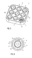
- Figures 4 and 5 show an exemplary embodiment of the storage device 1 of Figures 1 and 2 after the injection device has been secured to the needle assembly 5 and the pull linkages 11 have been disengaged.
- the needle assembly 5 is mounted on the injection device can be rotated freely (e.g., in the first direction) in the pocket 4 and removed from the pocket 4 so that the injection device with the needle assembly 5 mounted on it is ready for use.
- Figure 6 shows in more detail a top view of an exemplary embodiment of the needle assembly 5 within the pocket 4 in this state.
- the arrow in the exemplary embodiment shown in Figure 6 shows a first direction (clockwise in the figure) in which the needle assembly 5 may freely rotate within the pocket 4 without further tightening the needle assembly 5 to the injection device.
- further rotation of the needle assembly 5 in the first direction may cause the user to feel resistance as the second leg 17 of the projection 15 abuts the first and second ends 12, 13 of the pull linkage 11.
- the resistance may increase as the needle assembly 5 is rotated until the projection 15 bypasses the first end 12 of the pull linkage 11.
- the needle assembly 5 mounted on the injection device may be reinserted into the pocket 4.
- Figures 7 to 9 show how the needle assembly 5 may be removed from the injection device after the injection has been administered.
- the needle assembly 5 is reinserted into the pocket 4 (not necessarily the same pocket 4 from which it was removed).
- the injection device (and thus the needle assembly 5 secured thereto) is turned in a second direction (e.g., counter-clockwise).
- a second direction e.g., counter-clockwise
- the injection device may continue to rotate in the second direction until it disengages the needle assembly 5.
Abstract
Described is a needle assembly storage device (1). The storage device comprises a container (3), a pocket (4) formed in the container adapted to receive a needle assembly (5), and a pull linkage (11) connecting the needle assembly (5) to the container (3). The pull linkage (11) disengages the needle assembly (5) when sufficient rotational force has been applied to the needle assembly (5) in a first direction. A projection (15) on the needle assembly (5) prevents rotation of the needle assembly (5) in the pocket (4) in a second rotation direction opposite to the first direction.
Description
- The invention relates to a storage device for needle assemblies.
- Conventional injection device include a distal end for receiving single-use needle assemblies. Typically, a user will attach a needle assembly to the injection device (e.g., by a threaded connection) and remove the needle assembly after an injection has been administered. Removal of the needle assembly from the injection device bears the risk of injury (e.g., needle-stick) to the user. Therefore, various devices have been proposed to reduce this risk of injury.
- Further, when attaching the needle assembly to the injection device, an appropriate amount of torque is necessary. However, application of torque beyond the appropriate amount may result in overtightening (preventing removal of the needle assembly), fracture of the needle assembly and/or injection device, and/or injury to the user.
-
EP 1567209 B1 discusses a device for removing and replacing a needle cover.EP 1567215 B1 discusses a device for making and/or tightening fluid-guiding threaded connections, including Luer-lock type connections, - It is an object of the present invention to provide an improved needle assembly storage device.
- In an exemplary embodiment of the present invention, a needle assembly storage device comprises a container and a pocket formed in the container for receiving a needle assembly. The needle assembly may comprise a needle and a housing for receiving an injection device. The device further comprises a pull linkage connecting the needle assembly to the container. The pull linkage disengages the needle assembly when sufficient rotational force has been applied to the needle assembly in a first direction. A projection on the needle assembly prevents rotation of the needle assembly in the pocket in a second rotation direction opposite to the first direction.
- In an exemplary embodiment, the needle assembly includes a screw thread for coupling to the injection device. The screw thread may be an internal thread on an inner surface of the needle assembly. The projection may prevent rotation of the needle assembly within the pocket in the second direction when the projection abuts the pull linkage. The projection may have a first leg extending perpendicular to a tangent of an outer border of the needle assembly and a second leg as a sloped surface between the first leg and the outer border.
- In an exemplary embodiment, a peelable film may cover an opening of the needle assembly when the needle assembly is in the pocket.
- In an exemplary embodiment, the needle assembly comprises an annular collar to bear on a surface of the container. The pull linkage may include a sloped surface having a first end and a second end. Rotation of the needle assembly in the first direction generates resistance when the projection abuts the pull linkage.
- In an exemplary embodiment, a first tactile feedback is provided when the projection bypasses the pull linkage when the needle assembly is rotated in the first direction. A second tactile feedback may be provided when the projection abuts the pull linkage when the needle assembly is rotated in the second direction.
- Further scope of applicability of the present invention will become apparent from the detailed description given hereinafter. However, it should be understood that the detailed description and specific examples, while indicating preferred embodiments of the invention, are given by way of illustration only, since various changes and modifications within the spirit and scope of the invention will become apparent to those skilled in the art from this detailed description.
- The present invention will become more fully understood from the detailed description given below and the accompanying drawings wherein
- Figure 1
- shows a top view of an exemplary embodiment of a needle assembly storage device according to the present invention;
- Figure 2
- shows a perspective view of an exemplary embodiment of a needle assembly storage device according to the present invention;
- Figure 3
- shows a top view of a needle assembly within a pocket of an exemplary embodiment of a needle assembly storage device according to the present invention;
- Figure 4
- shows a top view of an exemplary embodiment of a needle assembly storage device according to the present invention;
- Figure 5
- shows a perspective view of an exemplary embodiment of a needle assembly storage device according to the present invention;
- Figure 6
- shows a top view of a needle assembly within a pocket of an exemplary embodiment of a needle assembly storage device according to the present invention;
- Figure 7
- shows a top view of a needle assembly within a pocket of an exemplary embodiment of a needle assembly storage device according to the present invention;
- Figure 8
- shows a perspective view of an exemplary embodiment of a needle assembly storage device according to the present invention; and
- Figure 9
- shows a top view of a needle assembly within a pocket of an exemplary embodiment of a needle assembly storage device according to the present invention.
- Corresponding parts are marked with the same reference symbols in all figures.
-
Figures 1 and 2 show a top view and a perspective view of an exemplary embodiment of a needleassembly storage device 1 forneedle assemblies 5, respectively. Thestorage device 1 comprises acontainer 3 with one ormore pockets 4. Eachpocket 4 may be sized and shaped to receive aneedle assembly 5. In the exemplary embodiments shown inFigure 1 ,needle assemblies 5 are received in each of thepockets 4. Those of skill in the art will understand that thecontainer 3 may be any size and/or shape (e.g., linear, box, etc.) and contain any number ofpockets 4. Prior to use, when theneedle assembly 5 is received in one of thepockets 4, thepocket 4 may be covered with a peelable film (not shown) or other device for maintaining a sterility of theneedle assembly 5. The peelable film may cover an opening of theneedle assembly 5 into which the injection device will be inserted for coupling thereto. The peelable film may be coupled to thepocket 4 by, for example, an adhesive. - Each
needle assembly 5 is sized and shaped to be received in one of thepockets 4. In an exemplary embodiment, the needle assembly includes a cylindrical housing having an inner threadedsurface 7 for engaging a threaded end of an injection device and a double-pointed needle 2. In an exemplary embodiment, theneedle assembly 5 has the shape of a cylindrical brimmed hat, with a top cover which theneedle 2 protrudes through along a longitudinal axis of theneedle assembly 5, and with a brim formed as anannular collar 6. In an exemplary embodiment, the threadedsurface 7 is right-handed, although in other embodiments, the threadedsurface 7 may be left-handed. - Each
pocket 4 of thecontainer 3 has acylindrical wall 8 with a container-sided end defining the contour of a circular opening 9 in asurface 10 of thecontainer 3. The inner diameter of thecylindrical wall 8 extends slightly the outer diameter of the cylindrical part of theneedle assembly 5 so that thepocket 4 can receive aneedle assembly 5. Furthermore the outer diameter of theannular collar 6 extends the diameter of the circular opening 9 so that theannular collar 6 of aneedle assembly 5 received in thepocket 4 bears on a surface surrounding the circular opening 9. - As shown in more detail in
Figure 3 , in an exemplary embodiment, eachneedle assembly 5 is connected to thecontainer 3 by one ormore pull linkages 11. A first end of each pulllinkage 11 is connected to (or formed integrally with) thecontainer 3, and a second end of each pulllinkage 11 comprises afirst end portion 12 which is connected to aneedle assembly 5 and defines a predetermined breaking point between thepull linkage 11 and theneedle assembly 5. Asecond end portion 13 of the second end of each pulllinkage 11 adjoins thefirst end portion 12 and is angled radially away from a circumference of theneedle assembly 5. Along the contour of the circular opening 9, the first andsecond end portions pull linkages 11 alternate so that thefirst end portion 12 of each pulllinkage 11 faces thesecond end portion 13 of a neighbouringpull linkage 11. - In an exemplary embodiment, the
outer border 14 of theannular collar 6 of theneedle assembly 5 includes at least oneprojection 15. In an exemplary embodiment in which there aremultiple projections 15, theprojections 15 may be placed at equal distances along theouter border 14 and correspond to the number ofpull linkages 11 connected to therespective needle assembly 5. Theprojection 15 may have a shape of a triangle with afirst leg 16 formed perpendicular to a tangent of theouter border 14 and asecond leg 17 having a sloped decline into theouter border 14. In the exemplary embodiment, when theneedle assembly 5 is turned in a first direction within thepocket 4, thefirst end 12 of thepull linkage 11 may follow (e.g., in contact) along theouter border 14, and resistance may be felt as thesecond leg 17 comes into contact with thefirst end 12 andsecond end 13 of thepull linkage 11. The resistance may increase until theprojection 15 bypasses thefirst end 12 of thepull linkage 11, at which point the user may be provided with a tactile feedback, e.g., a sudden decrease in the resistance. -
Figures 1 to 3 show an exemplary embodiment of aneedle assembly 5 in its initial position within thepocket 4 before a distal end of an injection device is coupled to theneedle assembly 5. When the distal end of the injection device is inserted into theneedle assembly 5, the injection device may be rotated in a first direction, e.g., clockwise, to secure theneedle assembly 5 thereto. Thepull linkages 11 prevent theneedle assembly 5 from rotating within thepocket 4 as it is being secured to the injection device. When theneedle assembly 5 has been properly secured to the injection device, further rotation in the first direction of theneedle assembly 5 may result in a disengagement of thepull linkages 11 from theouter border 14 of theneedle assembly 5. Thus, further rotation of the injection device in the first direction will not result in further tightening of theneedle assembly 5 thereto. Also, the disengagement of thepull linkage 11 may provide a tactile (and/or audible) feedback to the user. That is, while securing the injection device to theneedle assembly 5, the user may feel resistance while thepull linkages 11 secure thecontainer 3 to theneedle assembly 5. When a sufficient amount of torque is applied and theneedle assembly 5 disengages from thepull linkages 11, the user may feel a sudden decrease in resistance to further rotation of the injection device. -
Figures 4 and5 show an exemplary embodiment of thestorage device 1 ofFigures 1 and 2 after the injection device has been secured to theneedle assembly 5 and thepull linkages 11 have been disengaged. In this state, theneedle assembly 5 is mounted on the injection device can be rotated freely (e.g., in the first direction) in thepocket 4 and removed from thepocket 4 so that the injection device with theneedle assembly 5 mounted on it is ready for use. -
Figure 6 shows in more detail a top view of an exemplary embodiment of theneedle assembly 5 within thepocket 4 in this state. The arrow in the exemplary embodiment shown inFigure 6 shows a first direction (clockwise in the figure) in which theneedle assembly 5 may freely rotate within thepocket 4 without further tightening theneedle assembly 5 to the injection device. However, in an exemplary embodiment, further rotation of theneedle assembly 5 in the first direction may cause the user to feel resistance as thesecond leg 17 of theprojection 15 abuts the first and second ends 12, 13 of thepull linkage 11. The resistance may increase as theneedle assembly 5 is rotated until theprojection 15 bypasses thefirst end 12 of thepull linkage 11. - After administering an injection, the
needle assembly 5 mounted on the injection device may be reinserted into thepocket 4. -
Figures 7 to 9 show how theneedle assembly 5 may be removed from the injection device after the injection has been administered. In an exemplary embodiment, theneedle assembly 5 is reinserted into the pocket 4 (not necessarily thesame pocket 4 from which it was removed). To remove theneedle assembly 5 from the injection device, the injection device (and thus theneedle assembly 5 secured thereto) is turned in a second direction (e.g., counter-clockwise). When thefirst leg 16 of theprojection 15 abuts thefirst end 12 of thepull linkage 11, further rotation of theneedle assembly 5 in the second direction is prevented. However, the injection device may continue to rotate in the second direction until it disengages theneedle assembly 5. - After a
needle assembly 5 has been separated from the container and reinserted into apocket 4, it may difficult to remount thatneedle assembly 5 on the injection device, because theneedle assembly 5 will be free to rotate within thepocket 4 as the injection device attempts to engage theneedle assembly 5. Such a configuration may discourage reuse of previously usedneedle assemblies 5. - Those of skill in the art will understand that other exemplary embodiments of the invention use different numbers, geometries, alignments and/or orientations of the
pull linkages 11 and/or theprojections 15. Furthermore, one may use left-handed in place of right-handed screw threads 7 and correspondingly amended embodiments ofprojections 15 which prevent clockwise turnings of aneedle assembly 5 within apocket 4.
Claims (11)
- A needle assembly storage device (1), the storage device (1) comprising: a container (3);a pocket (4) formed in the container (3) adapted to receive a needle assembly (5);a pull linkage (11) connecting the needle assembly (5) to the container (3), the pull linkage (11) disengaging the needle assembly (5) when sufficient rotational force has been applied to the needle assembly (5) in a first direction; anda projection (15) on the needle assembly (5) preventing rotation of the needle assembly (5) in the pocket (4) in a second rotation direction opposite to the first direction.
- The storage device (1) according to claim 1, wherein the needle assembly (5) includes a screw thread (7) for coupling to the injection device.
- The storage device (1) according to claim 2, wherein the screw thread (7) is an internal thread on an inner surface of the needle assembly (5).
- The storage device (1) according to any of the preceding claims, wherein the projection (15) prevents rotation of the needle assembly (5) within the pocket (4) in the second direction when the projection (15) abuts the pull linkage (11).
- The storage device (1) according to any one of the preceding claims, wherein the projection (15) has a first leg (16) extending perpendicular to a tangent of an outer border (14) of the needle assembly (5) and a second leg (17) as a sloped surface between the first leg (16) and the outer border (14).
- The storage device (1) according to any of the preceding claims, wherein a peelable film covers an opening of the needle assembly (5) when the needle assembly (5) is in the pocket (4).
- The storage device (1) according to any of the preceding claims, wherein the needle assembly (5) comprises an annular collar (6) to bear on a surface of the container (3).
- The storage device (1) according to claim 1, wherein the pull linkage (11) includes a sloped surface having a first end (12) and a second end (13).
- The storage device (1) according to claim 1, wherein rotation of the needle assembly (5) in the first direction generates resistance when the projection (15) abuts the pull linkage (11).
- The storage device (1) according to claim 1, wherein a first tactile feedback is provided when the projection (15) bypasses the pull linkage (11) when the needle assembly (5) is rotated in the first direction.
- The storage device (1) according to claim 10, wherein a second tactile feedback
is provided when the projection (15) abuts the pull linkage (11) when the needle assembly (5) is rotated in the second direction.
Priority Applications (7)
| Application Number | Priority Date | Filing Date | Title |
|---|---|---|---|
| EP11158262A EP2500053A1 (en) | 2011-03-15 | 2011-03-15 | Needle assembly storage device |
| DK12708134.7T DK2686048T3 (en) | 2011-03-15 | 2012-03-09 | Storage device for needle devices |
| JP2013558381A JP6000990B2 (en) | 2011-03-15 | 2012-03-09 | Needle assembly storage device |
| EP20120708134 EP2686048B1 (en) | 2011-03-15 | 2012-03-09 | Needle assembly storage device |
| PCT/EP2012/054102 WO2012123354A1 (en) | 2011-03-15 | 2012-03-09 | Needle assembly storage device |
| US14/004,109 US9393360B2 (en) | 2011-03-15 | 2012-03-09 | Needle assembly storage device |
| CA2829509A CA2829509A1 (en) | 2011-03-15 | 2012-03-09 | Needle assembly storage device |
Applications Claiming Priority (1)
| Application Number | Priority Date | Filing Date | Title |
|---|---|---|---|
| EP11158262A EP2500053A1 (en) | 2011-03-15 | 2011-03-15 | Needle assembly storage device |
Publications (1)
| Publication Number | Publication Date |
|---|---|
| EP2500053A1 true EP2500053A1 (en) | 2012-09-19 |
Family
ID=44358244
Family Applications (2)
| Application Number | Title | Priority Date | Filing Date |
|---|---|---|---|
| EP11158262A Ceased EP2500053A1 (en) | 2011-03-15 | 2011-03-15 | Needle assembly storage device |
| EP20120708134 Not-in-force EP2686048B1 (en) | 2011-03-15 | 2012-03-09 | Needle assembly storage device |
Family Applications After (1)
| Application Number | Title | Priority Date | Filing Date |
|---|---|---|---|
| EP20120708134 Not-in-force EP2686048B1 (en) | 2011-03-15 | 2012-03-09 | Needle assembly storage device |
Country Status (6)
| Country | Link |
|---|---|
| US (1) | US9393360B2 (en) |
| EP (2) | EP2500053A1 (en) |
| JP (1) | JP6000990B2 (en) |
| CA (1) | CA2829509A1 (en) |
| DK (1) | DK2686048T3 (en) |
| WO (1) | WO2012123354A1 (en) |
Cited By (2)
| Publication number | Priority date | Publication date | Assignee | Title |
|---|---|---|---|---|
| EP3103504A1 (en) * | 2015-06-10 | 2016-12-14 | Buddha Brand Tattoo Limited | A type of rapid exchange of tattooing needle assembly |
| US10449346B2 (en) | 2015-06-05 | 2019-10-22 | Painful Pleasures, Inc. | Tattooing needle assembly |
Families Citing this family (4)
| Publication number | Priority date | Publication date | Assignee | Title |
|---|---|---|---|---|
| JP6307917B2 (en) * | 2014-02-14 | 2018-04-11 | 株式会社ジェイ・エム・エス | Breakage resistant engagement structure and needle base breakage resistant cover |
| JP7128814B2 (en) | 2016-12-06 | 2022-08-31 | エンベクタ コーポレイション | Apparatus for installing a pen needle assembly |
| USD864385S1 (en) * | 2017-07-13 | 2019-10-22 | iMed Technology, Inc. | Medical site cover mounting device |
| JP1643305S (en) * | 2019-02-20 | 2019-10-15 |
Citations (3)
| Publication number | Priority date | Publication date | Assignee | Title |
|---|---|---|---|---|
| EP0990446A1 (en) * | 1998-09-28 | 2000-04-05 | Becton Dickinson and Company | Pen needle magazine |
| EP1567215A2 (en) * | 2002-11-25 | 2005-08-31 | Tecpharma Licensing AG | Device for screwing together medium-guiding threaded connections, particularly luer lock connections |
| EP1567209B1 (en) | 2002-11-25 | 2009-01-21 | Tecpharma Licensing AG | Device for temporarily retaining a protective needle cap of an injection apparatus |
Family Cites Families (8)
| Publication number | Priority date | Publication date | Assignee | Title |
|---|---|---|---|---|
| EP0750518B1 (en) * | 1994-02-28 | 2002-01-02 | Novo Nordisk A/S | Needle unit |
| JPH10502551A (en) * | 1994-07-19 | 1998-03-10 | ノボ ノルディスク アクティーゼルスカブ | Needle magazine |
| US5873462A (en) * | 1997-09-12 | 1999-02-23 | Becton Dickinson And Company | Pen needle dispenser |
| AU2001272374A1 (en) * | 2000-08-03 | 2002-02-18 | Novo-Nordisk A/S | A needle magazine |
| CA2639320C (en) * | 2007-09-07 | 2016-10-25 | Becton, Dickinson And Company | Pen-needle assembly for preventing under-torquing and over-torquing of pen-needle |
| CN102791309B (en) * | 2010-03-05 | 2015-01-28 | 诺沃—诺迪斯克有限公司 | Two-part hinged needle magazine |
| US9186452B2 (en) * | 2010-08-16 | 2015-11-17 | Becton, Dickinson And Company | Pen needle dispensing apparatus |
| US8887912B2 (en) * | 2010-08-16 | 2014-11-18 | Becton, Dickinson And Company | Living hinge needle assembly for medicament delivery device |
-
2011
- 2011-03-15 EP EP11158262A patent/EP2500053A1/en not_active Ceased
-
2012
- 2012-03-09 JP JP2013558381A patent/JP6000990B2/en not_active Expired - Fee Related
- 2012-03-09 DK DK12708134.7T patent/DK2686048T3/en active
- 2012-03-09 WO PCT/EP2012/054102 patent/WO2012123354A1/en active Application Filing
- 2012-03-09 US US14/004,109 patent/US9393360B2/en active Active
- 2012-03-09 CA CA2829509A patent/CA2829509A1/en not_active Abandoned
- 2012-03-09 EP EP20120708134 patent/EP2686048B1/en not_active Not-in-force
Patent Citations (4)
| Publication number | Priority date | Publication date | Assignee | Title |
|---|---|---|---|---|
| EP0990446A1 (en) * | 1998-09-28 | 2000-04-05 | Becton Dickinson and Company | Pen needle magazine |
| EP1567215A2 (en) * | 2002-11-25 | 2005-08-31 | Tecpharma Licensing AG | Device for screwing together medium-guiding threaded connections, particularly luer lock connections |
| EP1567209B1 (en) | 2002-11-25 | 2009-01-21 | Tecpharma Licensing AG | Device for temporarily retaining a protective needle cap of an injection apparatus |
| EP1567215B1 (en) | 2002-11-25 | 2010-01-06 | Tecpharma Licensing AG | Device for screwing together medium-guiding threaded connections, particularly luer lock connections |
Cited By (2)
| Publication number | Priority date | Publication date | Assignee | Title |
|---|---|---|---|---|
| US10449346B2 (en) | 2015-06-05 | 2019-10-22 | Painful Pleasures, Inc. | Tattooing needle assembly |
| EP3103504A1 (en) * | 2015-06-10 | 2016-12-14 | Buddha Brand Tattoo Limited | A type of rapid exchange of tattooing needle assembly |
Also Published As
| Publication number | Publication date |
|---|---|
| EP2686048A1 (en) | 2014-01-22 |
| CA2829509A1 (en) | 2012-09-20 |
| JP2014513589A (en) | 2014-06-05 |
| DK2686048T3 (en) | 2015-07-27 |
| JP6000990B2 (en) | 2016-10-05 |
| US9393360B2 (en) | 2016-07-19 |
| EP2686048B1 (en) | 2015-04-22 |
| US20130341224A1 (en) | 2013-12-26 |
| WO2012123354A1 (en) | 2012-09-20 |
Similar Documents
| Publication | Publication Date | Title |
|---|---|---|
| EP2686048B1 (en) | Needle assembly storage device | |
| JP7321139B2 (en) | Pen needle outer cover concept | |
| EP2919834B1 (en) | Injection needle assembly | |
| CA2912391C (en) | Mechanical friction enhancement for threaded connection incorporating crushable ribs | |
| US20050271465A1 (en) | Device for making threaded connections, including Luer lock connections | |
| JP2014514096A (en) | Needle assembly for medical devices | |
| US20140048433A1 (en) | Needle assembly storage system | |
| WO2012093076A1 (en) | Cartridge holder for an injection device | |
| TWI772669B (en) | Needle shield remover and medicament delivery device including the same | |
| US9775955B2 (en) | Needle shield assembly | |
| US20160030682A1 (en) | Needle assembly retainer | |
| JP4323466B2 (en) | Connector cap | |
| JP2006334302A (en) | Catheter connector | |
| JPH11221278A (en) | Syringe needle cap |
Legal Events
| Date | Code | Title | Description |
|---|---|---|---|
| PUAI | Public reference made under article 153(3) epc to a published international application that has entered the european phase |
Free format text: ORIGINAL CODE: 0009012 |
|
| AK | Designated contracting states |
Kind code of ref document: A1 Designated state(s): AL AT BE BG CH CY CZ DE DK EE ES FI FR GB GR HR HU IE IS IT LI LT LU LV MC MK MT NL NO PL PT RO RS SE SI SK SM TR |
|
| AX | Request for extension of the european patent |
Extension state: BA ME |
|
| STAA | Information on the status of an ep patent application or granted ep patent |
Free format text: STATUS: THE APPLICATION HAS BEEN REFUSED |
|
| 18R | Application refused |
Effective date: 20121007 |