EP0902870B1 - Method for ice blasting - Google Patents
Method for ice blasting Download PDFInfo
- Publication number
- EP0902870B1 EP0902870B1 EP97929910A EP97929910A EP0902870B1 EP 0902870 B1 EP0902870 B1 EP 0902870B1 EP 97929910 A EP97929910 A EP 97929910A EP 97929910 A EP97929910 A EP 97929910A EP 0902870 B1 EP0902870 B1 EP 0902870B1
- Authority
- EP
- European Patent Office
- Prior art keywords
- ice
- particulates
- sheet
- tube
- continuously
- Prior art date
- Legal status (The legal status is an assumption and is not a legal conclusion. Google has not performed a legal analysis and makes no representation as to the accuracy of the status listed.)
- Expired - Lifetime
Links
Images


Classifications
-
- B—PERFORMING OPERATIONS; TRANSPORTING
- B24—GRINDING; POLISHING
- B24C—ABRASIVE OR RELATED BLASTING WITH PARTICULATE MATERIAL
- B24C1/00—Methods for use of abrasive blasting for producing particular effects; Use of auxiliary equipment in connection with such methods
- B24C1/08—Methods for use of abrasive blasting for producing particular effects; Use of auxiliary equipment in connection with such methods for polishing surfaces, e.g. smoothing a surface by making use of liquid-borne abrasives
- B24C1/083—Deburring
-
- B—PERFORMING OPERATIONS; TRANSPORTING
- B24—GRINDING; POLISHING
- B24C—ABRASIVE OR RELATED BLASTING WITH PARTICULATE MATERIAL
- B24C1/00—Methods for use of abrasive blasting for producing particular effects; Use of auxiliary equipment in connection with such methods
- B24C1/003—Methods for use of abrasive blasting for producing particular effects; Use of auxiliary equipment in connection with such methods using material which dissolves or changes phase after the treatment, e.g. ice, CO2
-
- B—PERFORMING OPERATIONS; TRANSPORTING
- B24—GRINDING; POLISHING
- B24C—ABRASIVE OR RELATED BLASTING WITH PARTICULATE MATERIAL
- B24C1/00—Methods for use of abrasive blasting for producing particular effects; Use of auxiliary equipment in connection with such methods
- B24C1/08—Methods for use of abrasive blasting for producing particular effects; Use of auxiliary equipment in connection with such methods for polishing surfaces, e.g. smoothing a surface by making use of liquid-borne abrasives
- B24C1/086—Descaling; Removing coating films
-
- F—MECHANICAL ENGINEERING; LIGHTING; HEATING; WEAPONS; BLASTING
- F25—REFRIGERATION OR COOLING; COMBINED HEATING AND REFRIGERATION SYSTEMS; HEAT PUMP SYSTEMS; MANUFACTURE OR STORAGE OF ICE; LIQUEFACTION SOLIDIFICATION OF GASES
- F25C—PRODUCING, WORKING OR HANDLING ICE
- F25C1/00—Producing ice
- F25C1/12—Producing ice by freezing water on cooled surfaces, e.g. to form slabs
- F25C1/14—Producing ice by freezing water on cooled surfaces, e.g. to form slabs to form thin sheets which are removed by scraping or wedging, e.g. in the form of flakes
- F25C1/142—Producing ice by freezing water on cooled surfaces, e.g. to form slabs to form thin sheets which are removed by scraping or wedging, e.g. in the form of flakes from the outer walls of cooled bodies
-
- F—MECHANICAL ENGINEERING; LIGHTING; HEATING; WEAPONS; BLASTING
- F25—REFRIGERATION OR COOLING; COMBINED HEATING AND REFRIGERATION SYSTEMS; HEAT PUMP SYSTEMS; MANUFACTURE OR STORAGE OF ICE; LIQUEFACTION SOLIDIFICATION OF GASES
- F25C—PRODUCING, WORKING OR HANDLING ICE
- F25C5/00—Working or handling ice
- F25C5/20—Distributing ice
-
- Y—GENERAL TAGGING OF NEW TECHNOLOGICAL DEVELOPMENTS; GENERAL TAGGING OF CROSS-SECTIONAL TECHNOLOGIES SPANNING OVER SEVERAL SECTIONS OF THE IPC; TECHNICAL SUBJECTS COVERED BY FORMER USPC CROSS-REFERENCE ART COLLECTIONS [XRACs] AND DIGESTS
- Y10—TECHNICAL SUBJECTS COVERED BY FORMER USPC
- Y10S—TECHNICAL SUBJECTS COVERED BY FORMER USPC CROSS-REFERENCE ART COLLECTIONS [XRACs] AND DIGESTS
- Y10S241/00—Solid material comminution or disintegration
- Y10S241/17—Ice crushers
Definitions
- the invention provides a method for continously producing a stream of ice particulates.
- ice blasting provides significant advantages over chemical surface treatment, blasting with sand or other abrasive materials, hydro-blasting, and blasting with steam or dry ice.
- the technique can be used to remove loose material, blips and burrs from production metal components, such as transmission channel plates after machining, and even softer material, such as organic polymeric materials, including plastic and rubber components. Because water in either frozen or liquid form is environmentally safe, and inexpensive, ice blasting does not pose a waste disposal problem.
- the technique can also be used for cleaning surfaces, removing paint or stripping contaminants from a surface, without the use of chemicals, abrasive materials, high temperatures, or steam.
- the ice particulates are mechanically sized, a process that can cause partial thawing of ice particulates so that they adhere together, producing larger particulates.
- the ice particulates are retained in storage hoppers, where they are physically at rest, while in contact with each other.
- the invention provides a method of continuously producing a stream of ice particulates, the method comprising:
- the invention can be carried out using an ice particulate-making apparatus that has a curved, refrigerated surface on which a thin ice sheet is formed, which is then fragmented into ice particulates that are fluidized and carried in a conduit of flowing air to impact onto the surface to be treated.
- the conduit is preferably smooth, and of substantially uniform cross-sectional area for flow, to minimize or eliminate ice particulate agglomeration and consequent clogging of the apparatus.
- the apparatus includes a refrigerated device with a curved surface, such as a cylindrical drum that is preferably rotatably mounted with outer surfaces adapted to form a thin layer of ice.
- the drum is horizontally mounted in a basin of water.
- An ice breaking tool such as a doctor-knife, is mounted near the side of the drum that is ice-coated, and extends along the length of the drum. The knife is oriented to intercept a leading edge of the ice sheet and fragment it into ice particulates as the drum rotates.
- An ice-receiving tube is located adjacent, and extends along the length of. the doctor-knife and is oriented so that a longitudinal slot in the tube is able to receive the ice particulates formed.
- One end of the tube is coupled to a hose supplying cold air, and the other end is coupled to an ice delivery hose that applies suction to the interior space of the tube.
- the delivery hose terminates in an ice blasting nozzle.
- the flow conduit of the ice particulates (tube and hoses) has a substantially smooth (i.e. free of obstructions and surface irregularities) inner surface, and substantially uniform cross-sectional area for flow, thereby avoiding low velocity spots where ice particulates may settle, accumulate, and cause blockages.
- the refrigerated drum is sprayed with water to form the thin ice sheet.
- the drum may be horizontally mounted, as preferred to form a uniform thickness ice-sheet, or may be inclined at an angle.
- the refrigerated drum is vertically-oriented and water is sprayed onto the drum to form a thin curved ice sheet.
- a doctor-knife extends along the length of the drum to fragment ice particulates from the sheet into an adjacent co-extensive ice-receiving tube.
- the refrigerated cylindrical surface is the interior surface of an annulus. At least one spray nozzle is mounted to direct water onto the cylindrical walls of the annulus to form a thin ice sheet. As before, a doctor-knife extending along the length of the cylindrical wall is used to fragment ice particulates of narrow size distribution from the ice sheet into a slot in an ice-receiving tube that is adjacent to and co-extensive with the knife.
- the entire apparatus for making ice particulates is enclosed in a pressurized vessel.
- the vessel may be maintained at a pressure in the range from about 20 to about 150 psig.
- pressurized air, or another gas is supplied to the apparatus to fluidize the ice particulates, and carry the ice particulates to a nozzle, or a plurality of nozzles, for blasting onto a surface.
- ice particulates are prepared by freezing water into a thin, curved sheet of ice.
- This thin, curved ice sheet already stressed as a result of the curvature, is relatively easily fragmented into ice particulates that are sized dependent on ice sheet thickness and radius of curvature.
- These ice particulates are drawn by suction pressure into a stream of cold, dry air that fluidizes and sweeps the particulates into a smooth surfaced flow conduit having a substantially constant cross-sectional area for flow.
- the ice particulates are ejected onto a surface of a substrate through a nozzle at high velocity to perform deburring, cleaning, or other operations, depending upon the velocity of the ice particulates and air stream.
- the invention provides a method, of continuously producing ice particulates, and continuously delivering these ice particulates at a controlled high velocity onto a substrate.
- the ice particulates are formed from fragmenting a "thin curved sheet" of ice.
- An example of such a cylindrical sheet is a sheet about 1.5 mm thick and with a radius of curvature of about 100 mm.
- this sheet is from about 1.0 to about 2.0 mm thick, and has a radius of curvature of about 50 mm to about 150 mm.
- larger or smaller apparatus are also useful.
- the ice particulates are kept in constant motion (and are "fluidized"), according to the invention, so that they do not come to rest relative to any part of the apparatus and do not come into stationary contact with each other to cohere and form larger ice particulate blocks that may cause blockages in the apparatus.
- the flow path along which the ice particulates are carried by a fluidizing gas, such as cold air is smooth and devoid of such abrupt changes in flow cross-sectional area as may lead to the deposition and subsequent accumulation of ice particulates to form blockages.
- the flow conduit has a diameter of about 25 to about 50 mm.
- components of the apparatus that come into contact with ice particulates are preferably fabricated from materials that are smooth and have low thermal conductivity.
- Plastic materials are preferred, especially non-stick plastics such as TEFLON, that may be used as an inner coating.
- the apparatus may be better understood with reference to the accompanying figures that schematically represent preferred embodiments of the apparatus for making ice particulates and delivering these through a nozzle onto the surface of a substrate.
- Reference to the embodiments of the figures facilitate an explanation of aspects of the invention.
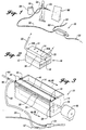
- FIGURE 1 schematically illustrates the ice-blasting operation.
- a unique ice maker 10 that produces ice particulates with controlled dimensions, as will be described later, supplies fluidized ice particulates into an ice and air medium delivery hose 52 to which is connected a nozzle 54 attached to a high pressure hose 56 that receives pressured air from device 58, either a compressor or a pressurized cylinder.
- the high pressure air is supplied through hose 56 to the nozzle 54 and creates a suction behind its entry point in the nozzle that draws ice particulates into the delivery hose 52, as will be explained later, and accelerates the speed of travel of the ice particulates so that they may be ejected from the nozzle 54, under the control of an operator (or under automated control), onto a surface 80 that is to be treated by ice-blasting.
- the unique ice maker 10 is not necessarily itself pressurized (although it may be in some embodiments), but in the illustrated embodiment air is drawn into it through hose 50, and an air-ice particulate mixture is delivered from it through delivery hose 52 to the nozzle 54. It is important to maintain a sufficient pressure drop between the air inlet 30a of tube 30 and air outlet 30b to cause sufficient air flow to fluidize the ice particulates formed and accelerate the particulates (see FIGURE 2).
- an ice maker 10 includes a housing 12 partially filled with water 13.
- a cylindrical drum 14 with an axial shaft 16 is rotatably mounted such that a portion of its outer cylindrical surface 15 is covered with water, when the housing contains an operating volume of water.
- the drum is refrigerated, usually by a plurality of channels in the interior of the cylindrical drum that carry a refrigerant (not shown).
- the drum 14 rotates in a counterclockwise direction around its axial shaft 16 that is coupled to an electric drive motor 18 at a rate that allows the formation of a suitably thick layer of ice on its surface.
- water in contact with its outer cylindrical surface freezes to form a thin sheet of ice 20.
- This sheet of ice is carried around to another side of the drum for removal as ice particulates 20a.
- the ice-cleared drum surface then continues to rotate and re-enters the water to form an ice sheet.
- the thin curved ice sheet is subject to stress as a result of its shape and a temperature gradient that extends through its thickness so that it is predisposed to fragment into ice particulates.
- the size distribution of these ice particulates is dependent upon the thickness, temperature, and the radius of curvature of the ice sheet, which are in turn dependent upon the rate of rotation and temperature of the drum, and the radius of the drum 14.
- FIGURES 4A and 4B The components of the apparatus that fragment the ice sheet are more clearly shown in FIGURES 4A and 4B.
- An ice-removal tool, or doctor-knife 22 is mounted on a support 24 so that the tip of the tool extends at an angle of about 45° to intercept a leading edge of the ice sheet 20.
- the doctor-knife 22 and its support 24 extend substantially along the entire length of the cylindrical drum 14, as shown in FIGURES 2 and 3.
- the stressed ice sheet fragments into ice particulates 20a.
- the ice particulates 20a then enter a tube of preferably substantially uniform inside cross-sectional area for flow, with a smooth inner surface, as shown in FIGURES 4A and 4C.
- the tube may have any one of many possible designs that may readily occur to one of skill in the art who has read this disclosure.
- these ice particulates enter into a slot 28 of an ice-receiving tube 30 that extends substantially along the entire length of the drum 14.
- the smooth inner-surfaced tube 30, shown in more detail in FIGURE 4C, is mounted so that one longitudinal edge 26 of the longitudinal slot is in contact with, and sealed against an upper end of the doctor-knife 22 by mechanical pressure.
- the other longitudinal edge 27 of the slot 28 curves over above the ice sheet and backward toward the leading edge of the ice sheet while extending downward to a position in touching relationship with the ice sheet 20.
- the edge 27 is therefore sealed against the surface of the ice sheet.
- ice particulates 20a are captured in the slot and enter the ice-receiving tube 30 where they are immediately fluidized and carried away, as will be explained later.
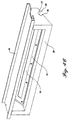
- the tube is optionally equipped with a longitudinal glass window 34 held in a frame 35. This optional glass window 34 extends along a substantial length of the upper surface of the ice-receiving tube 30, where a corresponding section of the tube has been removed.
- the ice-receiving tube is affixed to a support bracket 40, that extends along its upper outer surface.
- the bracket 40 is mounted to the housing 12 and is interconnected with an optional warning system, described below.
- the apparatus preferably has a warning system for detecting when the ice-receiving tube has been overfilled, or is being blocked. Under these circumstances, the continual rotation of the drum, forcing additional particulates into an already full tube, causes the tube 30 to lift away from the drum 14 thereby urging bracket 40 upward.
- This bracket is held in place, flush with the upper surface of the housing 12, by a series of pairs of compression-retaining bolts 42.
- Each of these bolts has a surrounding coil spring 44 that it maintains under compression between an upper surface of the bracket 40 and a washer near the top of the retaining bolt 42. Thus, as the bracket is urged upward, the springs compress. This compression is detected by a sensor 45 and automatically sounds an alarm.
- an air hose 50 is connected to an air inlet end 30a of the ice-receiving tube 30, and a media (ice and air) delivery hose 52 is connected to the other end 30b of the tube.
- cold compressed air supplied in hose 50 fluidizes ice particulates 20a, that are fragmented into tube 30, and carry these particulates into the media delivery hose 52.
- the ice-receiving tube 30 is not subjected to high pressure differential between its inside and the surroundings but is at close to atmospheric pressure in some embodiments. In other embodiments, as explained below, the entire apparatus may be enclosed in a pressurized vessel. Of more importance is the difference in pressure between tube air inlet and air outlet.
- the delivery hose terminates in an ice-blasting nozzle 54, that can be manually controlled by an operator or automatically operated.
- a diverter valve 62 reroutes the media through hose 64 to waste disposal.
- a high pressure air hose 56 is joined to the rear of the nozzle 54 to draw ice into the nozzle by suction and to impel the particulates at a controlled velocity through the nozzle 54.
- the tube 30 is not pressurized by air entering through hose 50, but air is drawn in by suction through hose 50 air and this air maintains the ice particulates in constant motion in a fluidized state.
- the drum 14 does not rotate in a container of water. Instead, the drum 14 is mounted in a container along with at least one spray nozzle that is oriented to spray water onto cylindrical surfaces of the drum, and thereby form an ice sheet on the refrigerated surface.
- water distributors 72 extend longitudinally along the length of the horizontally-oriented drum 14, and spray water from nozzle 70 onto the outer surface of the drum. Any excess water collects in the bottom of the container, and may be drained and recycled to the nozzles 70.
- horizontal orientation of the drum 14 is preferred, to form a thin ice sheet of substantially uniform thickness, other orientations are also possible.
- FIGURE 5 An alternative embodiment of the ice-maker apparatus is shown in FIGURE 5.
- the drum 14 is vertically-oriented and rotates about a central shaft 16.
- At least one spray nozzle 70 mounted near the cylindrical drum, directs a spray of water onto the cold (at least 0° C) cylindrical outer surfaces 15 of the drum. This spray of water freezes upon contact with the surfaces into an ice sheet.
- the curved ice sheet is broken into ice particulates when a leading edge of the sheet impacts against a front edge of a doctor-knife.
- the knife is mounted on a support (not shown), and preferably extends substantially along the length of the cylindrical surface parallel to the axial shaft of the drum.
- An ice-receiving tube 30 extends along the length of the doctor-knife, and a longitudinal slot of the tube intercepts ice particulates, directing these into the space within the tube 30, as explained before.
- an air hose 50 is attached to an upper open end 30a of the tube 30, while a media delivery hose 52 is connected to the lower open end 30b of the receiving tube 30.
- air drawn in through hose 50 fluidizes ice particulates in the tube 30 and carries the fluidized particulates into delivery hose 52, and thence to a delivery nozzle 54, as explained above.
- the ice sheet is formed on an internal cylindrical surface of a refrigerated cylindrical annulus 17.
- the refrigerated annulus 17 has an internal cylindrical space 75 surrounded by cylindrical walls.
- the annulus is held by friction between three rotating shafts 80 disposed in a triangular array against its outer surfaces so that it rotates at a controlled speed as the shafts rotate.
- Water, preferably from nozzles on a distributor 76, parallel to the central axis of the annulus 17, is sprayed onto the cold surrounding internal cylindrical walls of annulus 17. This water freezes into an ice sheet that is fragmented by a longitudinally extending doctor-knife tool, that is mounted to intercept the leading edge of the ice sheet inside the inner cylindrical space.
- the ice particulates are captured in an ice-receiving tube 30 through a longitudinally extending slot in the tube that extends substantially along the entire length of the surrounding cylindrical surface.
- An upper end 30a of the tube 30 is in fluid communication with an air supply hose 50, while a lower end 30b of the tube is in fluid communication with a media delivery hose 56.
- air is sucked into the upper open end of the tube, fluidizes ice particulates within the tube, and carries the fluidized ice particulates into the delivery hose 52 to an ice-blasting nozzle 54.
- the apparatus also optionally includes a diverter valve 62 for diverting ice particulates into a hose 64 when the nozzle 54 is shut off so that the ice making process is continuous.
- a series of tubes may be used, such that each tube is able to supply a continuous stream of ice particulates for ice-blasting, or a single tube may be divided into at least two, and possibly a plurality, of tube sections, each able to operate relatively independently.
- this embodiment of the invention allows simultaneous blasting of both sides.
- nozzles may be mounted on either side of the substrate, to automatically traverse both surfaces, thereby treating both front and rear surfaces of the substrate.
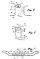
- an ice particulate receiving tube 30 is divided by a central diaphragm 30c into two tube sections 31 and 33, respectively.
- an air supply hose 55a enters into the inlet 31a of tube section 31, near the diaphragm 30c.
- the hose 55a is equipped with a control valve 57a to assist in controlling the flow of air through tube section 31.
- an ice particulate discharge hose 52b is connected to the open end 31b of tube section 31, so that ice particulates are continuously drawn from tube section 31 into hose 52b, and expelled through the nozzle.
- tube section 33 has an air inlet hose 55b attached to its inlet 33a. The outlet of the tube section 33b is coupled to an ice particulate delivery hose 52a, that draws fluidized ice particulates to the nozzle for ice blasting.
- receiving tube 30 can be divided into a series of sections for supplying a series of nozzles with ice particulates. Moreover, because the air supply to each nozzle can be individually controlled, the velocity of the ice particulates expelled from a nozzle connected to an ice tube section, can be individually controlled.
- nozzles can be connected to mechanical/electronic systems to automatically traverse surfaces of a stationary, or moving substrate.
- the method and apparatus of the invention are not limited to manual operation of an ice blast nozzle to treat a surface.
- the apparatus is ideally suited for automated cleaning of a continuous series of parts produced on a production line, such as is common in, for example, the automobile industry where the ice blasting apparatus of the invention may be used to deburr, or otherwise treat part surfaces.
- the invention provides the significant advantage of continuous operation for lengthy periods of time, thereby overcoming a significant problem encountered in prior art methods.
- fluidization of the ice particulates depends upon maintaining a pressure drop from the air inlet to the air outlet of the tube 30.
- the higher the pressure drop the more the fluidized air that is being supplied.
- the greater the amount of fluidized air per unit cross-sectional area for flow the higher the pressure at which the ice particulates leave the tube 30, and the higher the pressure at the delivery nozzle 54 (for a given length of delivery hose 52).
- an apparatus substantially as described above is enclosed in a pressurized vessel 72 preferably fitted with a pressure gauge 74.
- air is supplied to tube 30 through a hose 70, carrying cold compressed fluid, such as air.
- the apparatus is enclosed in a pressure vessel 72, so that the differential pressure between the inside and the outside of tube 30 is maintained at a level that the tube is able to tolerate, without fracture.
- the pressurized cold air is introduced into the inlet end of the tube, it fluidizes and carries away ice particulates from the outlet end 30b of the tube, which is in fluid communication with the delivery hose 52 and thence the nozzle 54.
- the discharge end of a compressor supplies compressed air to hose 70, and may also be used, with a control system and gauge 74, to regulate and maintain the pressure of the pressure vessel 72.
- the invention provides a method of ice-blasting surfaces with ice particulates.
- water is frozen into a thin curved sheet of ice, preferably by freezing the water onto a cylindrical surface.
- the sheet of ice is of such a thickness that temperature differences between its opposing curved faces results in stress that predisposes the ice sheet to being fragmented into ice particulates.
- This stress-cracked ice sheet is fragmented by impacting a leading edge of the ice sheet with a device, such as a doctor-knife, that extends along the leading edge of the ice sheet.
- the leading edge of the ice sheet is preferably of substantially uniform thickness along its length for more uniformly-sized ice particulates.
- Fragmented ice particulates are drawn, through suction, into a tube where the ice particulates are fluidized in cold air or in an other gas without melting.
- the fluidized ice particulates are then carried away into a delivery hose from which the ice particulates are ejected through a nozzle onto a surface that is being ice-blasted.
- high pressure air is introduced into the nozzle, thereby creating an area of low pressure behind its entry point in the nozzle.
- the low pressure area is in fluid communication with the delivery hose and draws, by suction, ice particulates from the fragmenting step into the tube and thence into the delivery hose.
- compressed air/gas is used to fluidize the ice particulates in the tube and carry the particulates to a nozzle tip.
Abstract
Description
- The invention provides a method for continously producing a stream of ice particulates.
- In recent years there has been increasing interest in the use of ice blasting techniques to treat surfaces. For certain applications, ice blasting provides significant advantages over chemical surface treatment, blasting with sand or other abrasive materials, hydro-blasting, and blasting with steam or dry ice. The technique can be used to remove loose material, blips and burrs from production metal components, such as transmission channel plates after machining, and even softer material, such as organic polymeric materials, including plastic and rubber components. Because water in either frozen or liquid form is environmentally safe, and inexpensive, ice blasting does not pose a waste disposal problem. The technique can also be used for cleaning surfaces, removing paint or stripping contaminants from a surface, without the use of chemicals, abrasive materials, high temperatures, or steam.
- Because of these apparent advantages, ice blasting has generated significant commercial interest which lead to the development of a variety of technologies designed to deliver a high pressure spray containing ice particulates for performing particular surface treatment procedures. Some of these technologies are shown, for example, in U.S. Patent Nos. 2,699,403; 4,389,820; 4,617,064; 4,703,590; 4,744,181; 4,965,968; 5,203,794; and 5,367,838. In particular, document No-A-9 416 861 shows a method of continuously producing a stream of ice particulates, the method comprising:
- (a) continuously freezing water on a curved surface into a thin, curved sheet of ice;
- (b) continuously fragmenting the curved sheet of ice to form ice particulates;
- (c) continuously separating fragmented ice particulates from the curved surface by continuously causing the ice particulates, as they are formed, to enter directly into a stream of air of sufficient velocity to fluidize the particulates;
- (d) maintaining the ice particulates in a fluidized state; and
- (e) continuously ejecting the fluidized ice particulates under controlled velocity from a nozzle. Despite all the effort devoted to ice-blasting equipment, the currently available equipment still suffers significant shortcomings that lead to job interruption and downtime for equipment maintenance. This is a particular disadvantage in using ice blasting in a continuous automated production line to treat surfaces of machined parts.
-
- In general, in the prior art equipment, the ice particulates are mechanically sized, a process that can cause partial thawing of ice particulates so that they adhere together, producing larger particulates. As a result, there is not only a wide distribution in the size of ice particulates produced, and the velocity at which these particulates are ejected from a nozzle onto the surface to be treated, but also frequent blockages that necessitate equipment downtime for clearing the blocked area. Moreover, in the available equipment, the ice particulates are retained in storage hoppers, where they are physically at rest, while in contact with each other. This results in ice particulates cohering to form larger ice blocks that ultimately cause blockages with resultant stoppage of the ice blasting operation due to an insufficient supply of ice particulates to the blasting nozzle. In other equipment, the ice particulates flow along a path with abruptly varying cross-sectional area for flow. This frequently causes the accumulation of fine ice particulates in certain low pressure areas. This accumulation also ultimately results in blockage of the apparatus, causing the ice blasting operation to come to an unscheduled stop.
- There yet exists a need for ice-blasting apparatus, and a method of ice blasting; that can be carried out continuously, with minimal risk of unscheduled stoppages due to ice blockages forming in the apparatus. Such an apparatus, and method of its operation, will allow more efficient ice-blasting operations, reducing labor costs for unscheduled stoppages, labor costs incurred in freeing the equipment of blockages, and permit more ready integration of ice blasting into an automated production line.
- The invention provides a method of continuously producing a stream of ice particulates, the method comprising:
- (a) continuously freezing water on a curved surface into a thin, curved sheet of ice, wherein a curvature of the curved sheet and a temperature gradient through the curved sheet induce stress cracks thereby predisposing the curved sheet to being fragmented into particulates;
- (b) continuously fragmenting the curved sheet of ice to form ice particulates;
- (c) continuously separating fragmented ice particulates from the curved surface by continuously causing the ice particulates, as they are formed, to enter directly into a stream of air of sufficient velocity to fluidize the particulates;
- (d) maintaining the ice particulates in a fluidized state; and
- (e) continuously ejecting the fluidized ice particulates under controlled velocity from a nozzle.
-
- In general, the invention can be carried out using an ice particulate-making apparatus that has a curved, refrigerated surface on which a thin ice sheet is formed, which is then fragmented into ice particulates that are fluidized and carried in a conduit of flowing air to impact onto the surface to be treated. The conduit is preferably smooth, and of substantially uniform cross-sectional area for flow, to minimize or eliminate ice particulate agglomeration and consequent clogging of the apparatus.
- The apparatus includes a refrigerated device with a curved surface, such as a cylindrical drum that is preferably rotatably mounted with outer surfaces adapted to form a thin layer of ice. In one embodiment, the drum is horizontally mounted in a basin of water. As the drum, that is refrigerated to a surface temperature of at least 0°C, rotates in the basin, a thin curved ice sheet forms on the cylindrical outer surfaces of the drum. An ice breaking tool. such as a doctor-knife, is mounted near the side of the drum that is ice-coated, and extends along the length of the drum. The knife is oriented to intercept a leading edge of the ice sheet and fragment it into ice particulates as the drum rotates. An ice-receiving tube is located adjacent, and extends along the length of. the doctor-knife and is oriented so that a longitudinal slot in the tube is able to receive the ice particulates formed. One end of the tube is coupled to a hose supplying cold air, and the other end is coupled to an ice delivery hose that applies suction to the interior space of the tube. The delivery hose terminates in an ice blasting nozzle. As ice particulates enter into the ice-receiving tube, the particulates are carried by a continuously flowing stream of cold air into the delivery hose and thence into the ice-blasting nozzle. The flow conduit of the ice particulates (tube and hoses) has a substantially smooth (i.e. free of obstructions and surface irregularities) inner surface, and substantially uniform cross-sectional area for flow, thereby avoiding low velocity spots where ice particulates may settle, accumulate, and cause blockages.
- The refrigerated drum is sprayed with water to form the thin ice sheet. The drum may be horizontally mounted, as preferred to form a uniform thickness ice-sheet, or may be inclined at an angle. In one such embodiment of the invention, the refrigerated drum is vertically-oriented and water is sprayed onto the drum to form a thin curved ice sheet. As explained above, a doctor-knife extends along the length of the drum to fragment ice particulates from the sheet into an adjacent co-extensive ice-receiving tube.
- The refrigerated cylindrical surface is the interior surface of an annulus. At least one spray nozzle is mounted to direct water onto the cylindrical walls of the annulus to form a thin ice sheet. As before, a doctor-knife extending along the length of the cylindrical wall is used to fragment ice particulates of narrow size distribution from the ice sheet into a slot in an ice-receiving tube that is adjacent to and co-extensive with the knife.
- The entire apparatus for making ice particulates is enclosed in a pressurized vessel. The vessel may be maintained at a pressure in the range from about 20 to about 150 psig. Moreover, in this embodiment pressurized air, or another gas, is supplied to the apparatus to fluidize the ice particulates, and carry the ice particulates to a nozzle, or a plurality of nozzles, for blasting onto a surface.
- According to the method of the invention, ice particulates are prepared by freezing water into a thin, curved sheet of ice. This thin, curved ice sheet, already stressed as a result of the curvature, is relatively easily fragmented into ice particulates that are sized dependent on ice sheet thickness and radius of curvature. These ice particulates are drawn by suction pressure into a stream of cold, dry air that fluidizes and sweeps the particulates into a smooth surfaced flow conduit having a substantially constant cross-sectional area for flow. At a terminal end of this flow conduit the ice particulates are ejected onto a surface of a substrate through a nozzle at high velocity to perform deburring, cleaning, or other operations, depending upon the velocity of the ice particulates and air stream.
- The foregoing aspects and many of the attendant advantages of this invention will become more readily appreciated as the same becomes better understood by reference to the following detailed description, when taken in conjunction with the accompanying drawings, wherein:
- FIGURE 1 is an illustration of a worker blasting a surface with ice particulates from an ice blasting device;
- FIGURE 2 is a simplified schematic of the ice particulate-making equipment;
- FIGURE 3 is a schematic perspective view of an embodiment of an ice-blasting apparatus;
- FIGURE 4A is an end view of an embodiment showing details of the ice removal tool and ice-receiving tube;
- FIGURE 4B is an end view of an embodiment including water spray nozzles for forming an ice sheet on a cylindrical surface of a rotating refrigerated drum;
- FIGURE 4C is a schematic perspective view of an embodiment of the ice-receiving tube, equipped with an optional window;
- FIGURE 5 is a schematic diagram showing another embodiment of the ice particulate-making apparatus wherein the rotating refrigerated drum is vertically oriented and receives a water spray to form an ice sheet on the outer surfaces of the drum;
- FIGURE 6 is yet another preferred embodiment of the ice particulate-making device wherein the rotating drum has a cylindrical internal surface on which a thin ice sheet is formed and fragmented into an ice-receiving tube;
- FIGURE 7 is a schematic cross-sectional illustration of an ice-particulate receiving tube, divided into two sections, for supplying two streams of fluidized ice particulates;
- FIGURE 8 is a schematic representation of an embodiment of the apparatus enclosed in a pressure vessel, and supplied with compressed air.
-
- The invention provides a method, of continuously producing ice particulates, and continuously delivering these ice particulates at a controlled high velocity onto a substrate. The ice particulates are formed from fragmenting a "thin curved sheet" of ice. In the specification and claims, this means a sheet of such curvature and thickness that, as a result, the sheet has residual stresses and a thermal gradient so that it is predisposed to ready fragmentation. An example of such a cylindrical sheet is a sheet about 1.5 mm thick and with a radius of curvature of about 100 mm. Preferably, this sheet is from about 1.0 to about 2.0 mm thick, and has a radius of curvature of about 50 mm to about 150 mm. Clearly, larger or smaller apparatus are also useful.
- The ice particulates are kept in constant motion (and are "fluidized"), according to the invention, so that they do not come to rest relative to any part of the apparatus and do not come into stationary contact with each other to cohere and form larger ice particulate blocks that may cause blockages in the apparatus. Moreover, the flow path along which the ice particulates are carried by a fluidizing gas, such as cold air, is smooth and devoid of such abrupt changes in flow cross-sectional area as may lead to the deposition and subsequent accumulation of ice particulates to form blockages. Preferably, the flow conduit has a diameter of about 25 to about 50 mm. In order to minimize any melting of the ice particulates that may lead to subsequent coherence or adherence and blockage, components of the apparatus that come into contact with ice particulates are preferably fabricated from materials that are smooth and have low thermal conductivity. Plastic materials are preferred, especially non-stick plastics such as TEFLON, that may be used as an inner coating.
- The apparatus may be better understood with reference to the accompanying figures that schematically represent preferred embodiments of the apparatus for making ice particulates and delivering these through a nozzle onto the surface of a substrate. Reference to the embodiments of the figures facilitate an explanation of aspects of the invention.
- FIGURE 1 schematically illustrates the ice-blasting operation. In accordance with an embodiment of the invention, a
unique ice maker 10 that produces ice particulates with controlled dimensions, as will be described later, supplies fluidized ice particulates into an ice and airmedium delivery hose 52 to which is connected anozzle 54 attached to ahigh pressure hose 56 that receives pressured air fromdevice 58, either a compressor or a pressurized cylinder. The high pressure air is supplied throughhose 56 to thenozzle 54 and creates a suction behind its entry point in the nozzle that draws ice particulates into thedelivery hose 52, as will be explained later, and accelerates the speed of travel of the ice particulates so that they may be ejected from thenozzle 54, under the control of an operator (or under automated control), onto asurface 80 that is to be treated by ice-blasting. As will become apparent later, theunique ice maker 10 is not necessarily itself pressurized (although it may be in some embodiments), but in the illustrated embodiment air is drawn into it throughhose 50, and an air-ice particulate mixture is delivered from it throughdelivery hose 52 to thenozzle 54. It is important to maintain a sufficient pressure drop between theair inlet 30a oftube 30 and air outlet 30b to cause sufficient air flow to fluidize the ice particulates formed and accelerate the particulates (see FIGURE 2). - Referring to the embodiment of FIGURES 2, 3, 4A and 4B, an
ice maker 10 includes ahousing 12 partially filled withwater 13. Acylindrical drum 14 with anaxial shaft 16 is rotatably mounted such that a portion of its outercylindrical surface 15 is covered with water, when the housing contains an operating volume of water. The drum is refrigerated, usually by a plurality of channels in the interior of the cylindrical drum that carry a refrigerant (not shown). As illustrated, thedrum 14 rotates in a counterclockwise direction around itsaxial shaft 16 that is coupled to anelectric drive motor 18 at a rate that allows the formation of a suitably thick layer of ice on its surface. As the refrigerated drum rotates, water in contact with its outer cylindrical surface freezes to form a thin sheet ofice 20. This sheet of ice is carried around to another side of the drum for removal asice particulates 20a. The ice-cleared drum surface then continues to rotate and re-enters the water to form an ice sheet. - It should be noted that the thin curved ice sheet is subject to stress as a result of its shape and a temperature gradient that extends through its thickness so that it is predisposed to fragment into ice particulates. The size distribution of these ice particulates is dependent upon the thickness, temperature, and the radius of curvature of the ice sheet, which are in turn dependent upon the rate of rotation and temperature of the drum, and the radius of the
drum 14. - The components of the apparatus that fragment the ice sheet are more clearly shown in FIGURES 4A and 4B. An ice-removal tool, or doctor-
knife 22 is mounted on asupport 24 so that the tip of the tool extends at an angle of about 45° to intercept a leading edge of theice sheet 20. The doctor-knife 22 and itssupport 24 extend substantially along the entire length of thecylindrical drum 14, as shown in FIGURES 2 and 3. Thus, as the ice sheet leading edge encounters the tip of the doctor-knife 22, the stressed ice sheet fragments intoice particulates 20a. Theice particulates 20a then enter a tube of preferably substantially uniform inside cross-sectional area for flow, with a smooth inner surface, as shown in FIGURES 4A and 4C. Within these constraints, the tube may have any one of many possible designs that may readily occur to one of skill in the art who has read this disclosure. In the illustrated embodiment, these ice particulates enter into aslot 28 of an ice-receivingtube 30 that extends substantially along the entire length of thedrum 14. The smooth inner-surfacedtube 30, shown in more detail in FIGURE 4C, is mounted so that onelongitudinal edge 26 of the longitudinal slot is in contact with, and sealed against an upper end of the doctor-knife 22 by mechanical pressure. The otherlongitudinal edge 27 of theslot 28 curves over above the ice sheet and backward toward the leading edge of the ice sheet while extending downward to a position in touching relationship with theice sheet 20. Theedge 27 is therefore sealed against the surface of the ice sheet. Thus,ice particulates 20a are captured in the slot and enter the ice-receivingtube 30 where they are immediately fluidized and carried away, as will be explained later. In order to allow inspection of the interior of the ice-receivingtube 30, the tube is optionally equipped with alongitudinal glass window 34 held in aframe 35. Thisoptional glass window 34 extends along a substantial length of the upper surface of the ice-receivingtube 30, where a corresponding section of the tube has been removed. The ice-receiving tube is affixed to asupport bracket 40, that extends along its upper outer surface. Thebracket 40 is mounted to thehousing 12 and is interconnected with an optional warning system, described below. - The apparatus preferably has a warning system for detecting when the ice-receiving tube has been overfilled, or is being blocked. Under these circumstances, the continual rotation of the drum, forcing additional particulates into an already full tube, causes the
tube 30 to lift away from thedrum 14 thereby urgingbracket 40 upward. This bracket is held in place, flush with the upper surface of thehousing 12, by a series of pairs of compression-retainingbolts 42. Each of these bolts has a surroundingcoil spring 44 that it maintains under compression between an upper surface of thebracket 40 and a washer near the top of the retainingbolt 42. Thus, as the bracket is urged upward, the springs compress. This compression is detected by asensor 45 and automatically sounds an alarm. This system allows early detection of potential or actual blockage so that necessary maintenance can be performed. As explained, however, such blockage should very rarely occur because the ice particulates formed are maintained in a fluidized state, in constant motion, and are not allowed to settle and cohere so that blockages are usually not able to form. However, blockages can result from inadequate fluidizing air supply or misaligned doctor-knife resulting in inadequate fracturing of the ice sheet. - Referring back to FIGURES 2, 3 and 4, an
air hose 50 is connected to anair inlet end 30a of the ice-receivingtube 30, and a media (ice and air)delivery hose 52 is connected to the other end 30b of the tube. Thus, cold compressed air supplied inhose 50 fluidizesice particulates 20a, that are fragmented intotube 30, and carry these particulates into themedia delivery hose 52. As will be explained below, the ice-receivingtube 30 is not subjected to high pressure differential between its inside and the surroundings but is at close to atmospheric pressure in some embodiments. In other embodiments, as explained below, the entire apparatus may be enclosed in a pressurized vessel. Of more importance is the difference in pressure between tube air inlet and air outlet. - Preferably, there is a smooth transition from
tube 30 todelivery hose 52 so that there are no internal obstructions to ice flow that may cause ice particulates to settle, adhere, cohere, and form blockages. The delivery hose, preferably with a smooth inner lining, terminates in an ice-blastingnozzle 54, that can be manually controlled by an operator or automatically operated. When the nozzle is shut off, adiverter valve 62 reroutes the media throughhose 64 to waste disposal. Thus, the ice-making apparatus is able to operate continuously without an accumulation ofparticulates 20a when blasting operations cease temporarily. This avoids the necessity to restart the apparatus, and the unsteady state operation associated with start up, and facilitates recommencing blasting operations. - In the illustrated embodiment, a high
pressure air hose 56 is joined to the rear of thenozzle 54 to draw ice into the nozzle by suction and to impel the particulates at a controlled velocity through thenozzle 54. The connection to the rear of the nozzle, with air directed to the nozzle tip, creates a suction-effect behind the nozzle so that ice particulates are drawn from the ice-receivingtube 30 and propelled to thenozzle 54. Thus, thetube 30 is not pressurized by air entering throughhose 50, but air is drawn in by suction throughhose 50 air and this air maintains the ice particulates in constant motion in a fluidized state. - In an alternative embodiment, illustrated in FIGURE 4B, the
drum 14 does not rotate in a container of water. Instead, thedrum 14 is mounted in a container along with at least one spray nozzle that is oriented to spray water onto cylindrical surfaces of the drum, and thereby form an ice sheet on the refrigerated surface. Thus, as shown in FIGURE 4B,water distributors 72 extend longitudinally along the length of the horizontally-orienteddrum 14, and spray water fromnozzle 70 onto the outer surface of the drum. Any excess water collects in the bottom of the container, and may be drained and recycled to thenozzles 70. Clearly, while horizontal orientation of thedrum 14 is preferred, to form a thin ice sheet of substantially uniform thickness, other orientations are also possible. - An alternative embodiment of the ice-maker apparatus is shown in FIGURE 5. In this embodiment, the
drum 14 is vertically-oriented and rotates about acentral shaft 16. At least onespray nozzle 70, mounted near the cylindrical drum, directs a spray of water onto the cold (at least 0° C) cylindricalouter surfaces 15 of the drum. This spray of water freezes upon contact with the surfaces into an ice sheet. Once again, the curved ice sheet is broken into ice particulates when a leading edge of the sheet impacts against a front edge of a doctor-knife. The knife is mounted on a support (not shown), and preferably extends substantially along the length of the cylindrical surface parallel to the axial shaft of the drum. An ice-receivingtube 30 extends along the length of the doctor-knife, and a longitudinal slot of the tube intercepts ice particulates, directing these into the space within thetube 30, as explained before. - As before, an
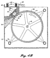
air hose 50 is attached to an upperopen end 30a of thetube 30, while amedia delivery hose 52 is connected to the lower open end 30b of the receivingtube 30. Thus, air drawn in throughhose 50 fluidizes ice particulates in thetube 30 and carries the fluidized particulates intodelivery hose 52, and thence to adelivery nozzle 54, as explained above. - In a yet further embodiment shown in FIGURE 6, the ice sheet is formed on an internal cylindrical surface of a refrigerated
cylindrical annulus 17. In this embodiment, therefrigerated annulus 17 has an internalcylindrical space 75 surrounded by cylindrical walls. The annulus is held by friction between threerotating shafts 80 disposed in a triangular array against its outer surfaces so that it rotates at a controlled speed as the shafts rotate. Water, preferably from nozzles on adistributor 76, parallel to the central axis of theannulus 17, is sprayed onto the cold surrounding internal cylindrical walls ofannulus 17. This water freezes into an ice sheet that is fragmented by a longitudinally extending doctor-knife tool, that is mounted to intercept the leading edge of the ice sheet inside the inner cylindrical space. As explained above, the ice particulates are captured in an ice-receivingtube 30 through a longitudinally extending slot in the tube that extends substantially along the entire length of the surrounding cylindrical surface. Anupper end 30a of thetube 30 is in fluid communication with anair supply hose 50, while a lower end 30b of the tube is in fluid communication with amedia delivery hose 56. Thus, air is sucked into the upper open end of the tube, fluidizes ice particulates within the tube, and carries the fluidized ice particulates into thedelivery hose 52 to an ice-blastingnozzle 54. - The apparatus also optionally includes a
diverter valve 62 for diverting ice particulates into ahose 64 when thenozzle 54 is shut off so that the ice making process is continuous. - A series of tubes may be used, such that each tube is able to supply a continuous stream of ice particulates for ice-blasting, or a single tube may be divided into at least two, and possibly a plurality, of tube sections, each able to operate relatively independently. Thus, for example, when the front and rear surfaces of a substrate must be ice blasted, this embodiment of the invention allows simultaneous blasting of both sides. In certain embodiments, nozzles may be mounted on either side of the substrate, to automatically traverse both surfaces, thereby treating both front and rear surfaces of the substrate. In the embodiment shown in FIGURE 7, an ice
particulate receiving tube 30 is divided by a central diaphragm 30c into twotube sections air supply hose 55a enters into the inlet 31a oftube section 31, near the diaphragm 30c. Preferably, thehose 55a is equipped with a control valve 57a to assist in controlling the flow of air throughtube section 31. As explained above, an ice particulate discharge hose 52b is connected to the open end 31b oftube section 31, so that ice particulates are continuously drawn fromtube section 31 into hose 52b, and expelled through the nozzle. Similarly,tube section 33 has an air inlet hose 55b attached to its inlet 33a. The outlet of the tube section 33b is coupled to an ice particulate delivery hose 52a, that draws fluidized ice particulates to the nozzle for ice blasting. Thus, it is clear, that receivingtube 30 can be divided into a series of sections for supplying a series of nozzles with ice particulates. Moreover, because the air supply to each nozzle can be individually controlled, the velocity of the ice particulates expelled from a nozzle connected to an ice tube section, can be individually controlled. - As indicated above, nozzles can be connected to mechanical/electronic systems to automatically traverse surfaces of a stationary, or moving substrate. Thus, the method and apparatus of the invention are not limited to manual operation of an ice blast nozzle to treat a surface. Instead, the apparatus is ideally suited for automated cleaning of a continuous series of parts produced on a production line, such as is common in, for example, the automobile industry where the ice blasting apparatus of the invention may be used to deburr, or otherwise treat part surfaces. The invention provides the significant advantage of continuous operation for lengthy periods of time, thereby overcoming a significant problem encountered in prior art methods.
- As indicated before, fluidization of the ice particulates depends upon maintaining a pressure drop from the air inlet to the air outlet of the
tube 30. In general, for a given tube cross-sectional area for flow, the higher the pressure drop, the more the fluidized air that is being supplied. Also, the greater the amount of fluidized air per unit cross-sectional area for flow, the higher the pressure at which the ice particulates leave thetube 30, and the higher the pressure at the delivery nozzle 54 (for a given length of delivery hose 52). - In accordance with the embodiment of FIGURE 8, an apparatus substantially as described above, is enclosed in a
pressurized vessel 72 preferably fitted with apressure gauge 74. However, in this instance, air is supplied totube 30 through ahose 70, carrying cold compressed fluid, such as air. Thus, while thetube 30 is pressurized, the apparatus is enclosed in apressure vessel 72, so that the differential pressure between the inside and the outside oftube 30 is maintained at a level that the tube is able to tolerate, without fracture. As the pressurized cold air is introduced into the inlet end of the tube, it fluidizes and carries away ice particulates from the outlet end 30b of the tube, which is in fluid communication with thedelivery hose 52 and thence thenozzle 54. - This particular embodiment is particularly useful for large industrial applications. In this event, the discharge end of a compressor supplies compressed air to
hose 70, and may also be used, with a control system andgauge 74, to regulate and maintain the pressure of thepressure vessel 72. - The invention provides a method of ice-blasting surfaces with ice particulates. In accordance with the method, water is frozen into a thin curved sheet of ice, preferably by freezing the water onto a cylindrical surface. The sheet of ice is of such a thickness that temperature differences between its opposing curved faces results in stress that predisposes the ice sheet to being fragmented into ice particulates. This stress-cracked ice sheet is fragmented by impacting a leading edge of the ice sheet with a device, such as a doctor-knife, that extends along the leading edge of the ice sheet. The leading edge of the ice sheet is preferably of substantially uniform thickness along its length for more uniformly-sized ice particulates. Fragmented ice particulates are drawn, through suction, into a tube where the ice particulates are fluidized in cold air or in an other gas without melting. The fluidized ice particulates are then carried away into a delivery hose from which the ice particulates are ejected through a nozzle onto a surface that is being ice-blasted. In order to fluidize, carry and accelerate the speed of the ice particulates entering the tube, in one embodiment high pressure air is introduced into the nozzle, thereby creating an area of low pressure behind its entry point in the nozzle. The low pressure area is in fluid communication with the delivery hose and draws, by suction, ice particulates from the fragmenting step into the tube and thence into the delivery hose. The higher pressure at the vicinity of the nozzle tip, ahead of the entry point of the high pressure air, accelerates the ice particulates for the ice-blasting operation. In another embodiment, compressed air/gas is used to fluidize the ice particulates in the tube and carry the particulates to a nozzle tip.
Claims (7)
- A method of continuously producing a stream of ice particulates, the method comprising:(a) continuously freezing water (13) on a curved surface (14) into a thin, curved sheet of ice (20), wherein a curvature of the curved sheet and a temperature gradient through the curved sheet induce stress cracks thereby predisposing the curved sheet to being fragmented into particulates;(b) continuously fragmenting the curved sheet of ice to form ice particulates;(c) continuously separating fragmented ice particulates from the curved surface by continuously causing the ice particulates, as they are formed, to enter directly into a stream of air of sufficient velocity to fluidize the particulates;(d) maintaining the ice particulates in a fluidized state; and(e) continuously ejecting the fluidized ice particulates under controlled velocity from a nozzle (54).
- The method of Claim 1, wherein the step of continuously freezing comprises freezing into a cylindrically curved sheet.
- The method of Claim 1, wherein the step of causing the ice particulates to enter the stream of air comprises drawing the ice particulates into the stream of air by suction pressure.
- The method of Claim 1, wherein step (c) and step (d) are carried out without melting of the ice particulates as to cause significant coherence of ice particulates.
- The method of Claim 1, wherein the fragmenting of the curved sheet of ice comprises impacting a leading edge of the ice sheet with a knife edge (22) to separate the ice particulates from the sheet of ice.
- The method of Claim 1, wherein the curved surface comprises a drum (14) mounted horizontally in a container (12) partially filled with the water.
- The method of Claim 1, wherein the curved sheet of ice is formed by spraying the water onto the curved surface wherein the curved surface comprises a cylindrical, vertically mounted drum (14).
Applications Claiming Priority (3)
| Application Number | Priority Date | Filing Date | Title |
|---|---|---|---|
| US660905 | 1996-06-07 | ||
| US08/660,905 US5913711A (en) | 1996-06-07 | 1996-06-07 | Method for ice blasting |
| PCT/US1997/010070 WO1997046838A1 (en) | 1996-06-07 | 1997-06-05 | Apparatus and method for ice blasting |
Publications (3)
| Publication Number | Publication Date |
|---|---|
| EP0902870A1 EP0902870A1 (en) | 1999-03-24 |
| EP0902870A4 EP0902870A4 (en) | 2000-01-19 |
| EP0902870B1 true EP0902870B1 (en) | 2004-01-14 |
Family
ID=24651426
Family Applications (1)
| Application Number | Title | Priority Date | Filing Date |
|---|---|---|---|
| EP97929910A Expired - Lifetime EP0902870B1 (en) | 1996-06-07 | 1997-06-05 | Method for ice blasting |
Country Status (11)
| Country | Link |
|---|---|
| US (3) | US5913711A (en) |
| EP (1) | EP0902870B1 (en) |
| JP (1) | JP2002508053A (en) |
| AT (1) | ATE257936T1 (en) |
| AU (1) | AU3386297A (en) |
| CA (1) | CA2257384C (en) |
| DE (1) | DE69727219T2 (en) |
| DK (1) | DK0902870T3 (en) |
| ES (1) | ES2214625T3 (en) |
| PT (1) | PT902870E (en) |
| WO (1) | WO1997046838A1 (en) |
Families Citing this family (49)
| Publication number | Priority date | Publication date | Assignee | Title |
|---|---|---|---|---|
| DE19735598A1 (en) * | 1997-08-15 | 1999-02-18 | Maja Maschinenfabrik Herrmann | Ice splinters production machine, for keeping meat fresh |
| US6726693B2 (en) * | 2000-11-10 | 2004-04-27 | Pearl Technology Holdings, Llc | Tissue resurfacing using biocompatible materials |
| US6306119B1 (en) * | 1999-01-20 | 2001-10-23 | Pearl Technology Holdings, Llc | Skin resurfacing and treatment using biocompatible materials |
| US6328631B1 (en) * | 1999-04-28 | 2001-12-11 | Mayekawa Mfg. Co., Ltd. | Method and apparatus for surface processing using ice slurry |
| IL156749A0 (en) * | 2001-01-02 | 2004-02-08 | Eyal Rozenshpeer | Cutting and removal of biological tissue by pressurized propulsion of ice particles |
| JP2002318042A (en) * | 2001-04-19 | 2002-10-31 | Hoshizaki Electric Co Ltd | Auger type ice making machine |
| US6536220B2 (en) | 2001-05-11 | 2003-03-25 | Universal Ice Blast, Inc. | Method and apparatus for pressure-driven ice blasting |
| US6557355B2 (en) | 2001-10-09 | 2003-05-06 | Roman Niechcial | Methods and apparatus for creating and using ice pellets |
| US7040962B2 (en) * | 2003-11-19 | 2006-05-09 | Fuji Seiki Machine Works, Ltd. | Ice blasting apparatus and trimming method for film insert molding |
| US20050123418A1 (en) * | 2003-12-08 | 2005-06-09 | Manole Dan M. | Compact compressors and refrigeration systems |
| WO2005097364A1 (en) * | 2004-03-31 | 2005-10-20 | Ecolab Inc. | System for semi-automatic line cleaning |
| US20060169715A1 (en) * | 2004-11-09 | 2006-08-03 | Jorg Emmendorfer | Controller-based management of a fluid dispensing system |
| US20060097003A1 (en) * | 2004-11-09 | 2006-05-11 | Joerg Emmendoerfer | Chemical dispense system for cleaning components of a fluid dispensing system |
| US7311224B2 (en) * | 2004-11-09 | 2007-12-25 | Ecolab Inc. | Chemical dispense system for cleaning components of a fluid dispensing system |
| US20060113322A1 (en) * | 2004-11-09 | 2006-06-01 | Maser Bryan A | Monitoring operation of a fluid dispensing system |
| US20060175352A1 (en) * | 2004-11-09 | 2006-08-10 | Jorg Emmendorfer | Cleaning processes for a fluid dispensing system |
| US20070095859A1 (en) * | 2005-10-31 | 2007-05-03 | Maser Bryan A | Controller-based management of a fluid dispensing system |
| ATE439212T1 (en) * | 2007-04-05 | 2009-08-15 | Rosa Rotstein | DEVICE AND METHOD FOR SURFACE PROCESSING OR SURFACE TREATMENT USING DRY ICE GRANULES |
| EP2065671A1 (en) * | 2007-11-29 | 2009-06-03 | Ugo Nevi | Machine shooting bullets of ice |
| KR100843638B1 (en) | 2008-04-23 | 2008-07-09 | 클린로드 주식회사 | Cleaning method for a street facilities |
| US8731841B2 (en) * | 2008-10-31 | 2014-05-20 | The Invention Science Fund I, Llc | Compositions and methods for therapeutic delivery with frozen particles |
| US9050317B2 (en) | 2008-10-31 | 2015-06-09 | The Invention Science Fund I, Llc | Compositions and methods for therapeutic delivery with frozen particles |
| US20100111857A1 (en) | 2008-10-31 | 2010-05-06 | Boyden Edward S | Compositions and methods for surface abrasion with frozen particles |
| US8731840B2 (en) | 2008-10-31 | 2014-05-20 | The Invention Science Fund I, Llc | Compositions and methods for therapeutic delivery with frozen particles |
| US9072688B2 (en) * | 2008-10-31 | 2015-07-07 | The Invention Science Fund I, Llc | Compositions and methods for therapeutic delivery with frozen particles |
| US9060934B2 (en) | 2008-10-31 | 2015-06-23 | The Invention Science Fund I, Llc | Compositions and methods for surface abrasion with frozen particles |
| US8793075B2 (en) | 2008-10-31 | 2014-07-29 | The Invention Science Fund I, Llc | Compositions and methods for therapeutic delivery with frozen particles |
| US8409376B2 (en) | 2008-10-31 | 2013-04-02 | The Invention Science Fund I, Llc | Compositions and methods for surface abrasion with frozen particles |
| US8551505B2 (en) | 2008-10-31 | 2013-10-08 | The Invention Science Fund I, Llc | Compositions and methods for therapeutic delivery with frozen particles |
| US9072799B2 (en) | 2008-10-31 | 2015-07-07 | The Invention Science Fund I, Llc | Compositions and methods for surface abrasion with frozen particles |
| US9050070B2 (en) | 2008-10-31 | 2015-06-09 | The Invention Science Fund I, Llc | Compositions and methods for surface abrasion with frozen particles |
| US8545855B2 (en) | 2008-10-31 | 2013-10-01 | The Invention Science Fund I, Llc | Compositions and methods for surface abrasion with frozen particles |
| US9060926B2 (en) | 2008-10-31 | 2015-06-23 | The Invention Science Fund I, Llc | Compositions and methods for therapeutic delivery with frozen particles |
| US8725420B2 (en) | 2008-10-31 | 2014-05-13 | The Invention Science Fund I, Llc | Compositions and methods for surface abrasion with frozen particles |
| US8721583B2 (en) | 2008-10-31 | 2014-05-13 | The Invention Science Fund I, Llc | Compositions and methods for surface abrasion with frozen particles |
| US8762067B2 (en) * | 2008-10-31 | 2014-06-24 | The Invention Science Fund I, Llc | Methods and systems for ablation or abrasion with frozen particles and comparing tissue surface ablation or abrasion data to clinical outcome data |
| US8788211B2 (en) | 2008-10-31 | 2014-07-22 | The Invention Science Fund I, Llc | Method and system for comparing tissue ablation or abrasion data to data related to administration of a frozen particle composition |
| JP5603887B2 (en) * | 2009-03-14 | 2014-10-08 | マーヤ−マシイネンファブリーク・ヘルマン・シル・ゲゼルシャフト・ミト・ベシュレンクテル・ハフツング・ウント・コンパニー・コマンディトゲゼルシャフト | Flake ice production equipment |
| US20100282026A1 (en) * | 2009-05-11 | 2010-11-11 | Baker Hughes Incorporated | Method and system for automated earth boring drill bit manufacturing |
| JP5362459B2 (en) * | 2009-06-23 | 2013-12-11 | 公益財団法人鉄道総合技術研究所 | Freezing layer generator |
| US20110066162A1 (en) * | 2009-09-16 | 2011-03-17 | Vandolay, Inc. | Cryo-micro-dermabrasion |
| JP5329384B2 (en) * | 2009-12-24 | 2013-10-30 | ホシザキ電機株式会社 | Drum ice machine |
| JP5576663B2 (en) * | 2010-01-12 | 2014-08-20 | ホシザキ電機株式会社 | Drum ice machine |
| CN106264671B (en) * | 2015-05-14 | 2018-11-23 | 惠州海卓科赛医疗有限公司 | A kind of high cutting force medical water jet |
| AU2017210772B9 (en) | 2016-01-27 | 2019-08-08 | Coulson Ice Blast Ltd. | Ice blasting system and method |
| CN108870820B (en) * | 2018-06-29 | 2020-09-11 | 芜湖拓达电子科技有限公司 | Ice block crushing device for fresh-keeping and refrigeration of aquatic products |
| AU2020417294B2 (en) | 2019-12-31 | 2024-04-04 | Cold Jet, Llc | Method and apparatus for enhanced blast stream |
| KR102317462B1 (en) * | 2020-02-27 | 2021-10-27 | 구하서 | Ice manufacturing device |
| CN112695706B (en) * | 2020-12-28 | 2022-04-19 | 四川大学 | Device and method for reducing flood discharge atomization degree |
Family Cites Families (23)
| Publication number | Priority date | Publication date | Assignee | Title |
|---|---|---|---|---|
| US2549215A (en) * | 1942-07-30 | 1951-04-17 | Mansted Svend Axel Jorgen | Method of and means for producing broken ice |
| US2699403A (en) * | 1952-05-24 | 1955-01-11 | Emmett J Courts | Means and methods for cleaning and polishing automobiles |
| US2860490A (en) * | 1952-07-25 | 1958-11-18 | Vilter Mfg Co | Method and apparatus for production of super-cooled ice |
| US2749722A (en) * | 1952-09-19 | 1956-06-12 | Frank W Knowles | Apparatus for making ice in small pieces |
| US2758451A (en) * | 1953-05-14 | 1956-08-14 | Akshun Mfg Company | Flake ice making machine and water distributor for use therein |
| US3403532A (en) * | 1966-12-01 | 1968-10-01 | Frank W. Knowles | Flake ice-making machine |
| US4389820A (en) * | 1980-12-29 | 1983-06-28 | Lockheed Corporation | Blasting machine utilizing sublimable particles |
| PH19804A (en) * | 1981-12-21 | 1986-07-08 | Saphim Prod Hielo Marino | Machine for making ice flakes from sea water or fresh water |
| US4538428A (en) * | 1984-04-02 | 1985-09-03 | Wilkerson Kenneth L | Ice-making machine |
| US4617064A (en) * | 1984-07-31 | 1986-10-14 | Cryoblast, Inc. | Cleaning method and apparatus |
| DK550884A (en) * | 1984-11-20 | 1986-05-21 | Knud Erik Westergaard | PROCEDURE AND APPARATUS FOR PARTICULATE BLASTING WITH PARTICLES OF A MATERIAL CHANGING CONDITION FORM |
| GB8505429D0 (en) * | 1985-03-02 | 1985-04-03 | Kue Eng Ltd | Blast cleaning |
| US4744181A (en) * | 1986-11-17 | 1988-05-17 | Moore David E | Particle-blast cleaning apparatus and method |
| JPH0744166B2 (en) * | 1990-07-31 | 1995-05-15 | 三菱電機株式会社 | Semiconductor wafer cleaning equipment |
| DE4115142A1 (en) * | 1991-05-08 | 1992-11-12 | Biforce Anstalt | Crushed ice mfg. device - has rotating cooled cylinder and filling level detection circuit controlling drive |
| US5203794A (en) * | 1991-06-14 | 1993-04-20 | Alpheus Cleaning Technologies Corp. | Ice blasting apparatus |
| WO1993024275A1 (en) | 1992-06-01 | 1993-12-09 | Ice Blast International Ltd. | Particle blasting utilizing crystalline ice |
| US5249426A (en) * | 1992-06-02 | 1993-10-05 | Alpheus Cleaning Technologies Corp. | Apparatus for making and delivering sublimable pellets |
| TW218852B (en) * | 1992-12-23 | 1994-01-11 | D Fraresso William | Apparatus for real time ice supply to ice blasting system |
| CA2113291A1 (en) * | 1993-01-26 | 1994-07-27 | William D. Fraresso | Apparatus for real time ice supply to ice blasting system |
| US5520572A (en) * | 1994-07-01 | 1996-05-28 | Alpheus Cleaning Technologies Corp. | Apparatus for producing and blasting sublimable granules on demand |
| US5448894A (en) * | 1994-09-21 | 1995-09-12 | North Star Ice Equipment Corporation | Disk flake ice machine |
| US5623831A (en) * | 1995-05-10 | 1997-04-29 | Mesher; Terry | Fluidized particle production system and process |
-
1996
- 1996-06-07 US US08/660,905 patent/US5913711A/en not_active Expired - Fee Related
-
1997
- 1997-06-05 DK DK97929910T patent/DK0902870T3/en active
- 1997-06-05 JP JP50092498A patent/JP2002508053A/en not_active Ceased
- 1997-06-05 CA CA002257384A patent/CA2257384C/en not_active Expired - Fee Related
- 1997-06-05 AU AU33862/97A patent/AU3386297A/en not_active Abandoned
- 1997-06-05 ES ES97929910T patent/ES2214625T3/en not_active Expired - Lifetime
- 1997-06-05 DE DE69727219T patent/DE69727219T2/en not_active Expired - Fee Related
- 1997-06-05 WO PCT/US1997/010070 patent/WO1997046838A1/en active IP Right Grant
- 1997-06-05 AT AT97929910T patent/ATE257936T1/en not_active IP Right Cessation
- 1997-06-05 EP EP97929910A patent/EP0902870B1/en not_active Expired - Lifetime
- 1997-06-05 PT PT97929910T patent/PT902870E/en unknown
-
1998
- 1998-03-30 US US09/050,616 patent/US6001000A/en not_active Expired - Fee Related
-
1999
- 1999-12-14 US US09/465,211 patent/US6270394B1/en not_active Expired - Lifetime
Also Published As
| Publication number | Publication date |
|---|---|
| US6270394B1 (en) | 2001-08-07 |
| ES2214625T3 (en) | 2004-09-16 |
| EP0902870A1 (en) | 1999-03-24 |
| ATE257936T1 (en) | 2004-01-15 |
| DK0902870T3 (en) | 2004-05-03 |
| DE69727219T2 (en) | 2004-12-02 |
| CA2257384A1 (en) | 1997-12-11 |
| EP0902870A4 (en) | 2000-01-19 |
| PT902870E (en) | 2004-05-31 |
| WO1997046838A1 (en) | 1997-12-11 |
| AU3386297A (en) | 1998-01-05 |
| DE69727219D1 (en) | 2004-02-19 |
| JP2002508053A (en) | 2002-03-12 |
| CA2257384C (en) | 2005-03-01 |
| US5913711A (en) | 1999-06-22 |
| US6001000A (en) | 1999-12-14 |
Similar Documents
| Publication | Publication Date | Title |
|---|---|---|
| EP0902870B1 (en) | Method for ice blasting | |
| WO1997046838B1 (en) | Apparatus and method for ice blasting | |
| US4707951A (en) | Installation for the projection of particles of dry ice | |
| US5820447A (en) | Ice blasting cleaning system | |
| US6536220B2 (en) | Method and apparatus for pressure-driven ice blasting | |
| KR19990014670A (en) | Fluidized Particle Manufacturing System and Method | |
| JP2007203448A (en) | Dry ice blasting device | |
| WO1994016861A1 (en) | Apparatus for real time ice supply to ice blasting system | |
| US4922664A (en) | Liquid sand blast nozzle and method of using same | |
| CN112584974B (en) | Sand blasting device and sand blasting method | |
| CA2487309A1 (en) | Apparatus and method for ice blasting | |
| CA2111648A1 (en) | Method for blasting ice particles in a surface treatment process | |
| WO2020158305A1 (en) | Slurry supply device, wet blasting device, and slurry supply method | |
| EP0041797A1 (en) | Surface treatment | |
| WO1994023896A1 (en) | Ice blast particle transport system for ice fracturing system | |
| KR200346255Y1 (en) | An Apparatus for Ice-Blasting Using an Ice Particles | |
| JP2893126B2 (en) | Ice grain shot blasting equipment | |
| US20020146967A1 (en) | Method and apparatus for ice blasting | |
| JP2814228B2 (en) | Abrasive material supply device for blast cleaning | |
| CA2121269A1 (en) | Crystalline ice particle mixture for optimum ice blast surface treatment | |
| JPH10249732A (en) | Abrasive material supply and spray method and device for blasting | |
| KR20050073137A (en) | An apparatus for ice-blasting using an ice particles | |
| US6557355B2 (en) | Methods and apparatus for creating and using ice pellets | |
| JP2696158B2 (en) | Method for removing mold release agent and the like and apparatus for removing mold release agent and the like from mold | |
| AU657104B2 (en) | Improved road repair machines |
Legal Events
| Date | Code | Title | Description |
|---|---|---|---|
| PUAI | Public reference made under article 153(3) epc to a published international application that has entered the european phase |
Free format text: ORIGINAL CODE: 0009012 |
|
| 17P | Request for examination filed |
Effective date: 19990107 |
|
| AK | Designated contracting states |
Kind code of ref document: A1 Designated state(s): AT BE CH DE DK ES FI FR GB GR IE IT LI LU MC NL PT SE |
|
| A4 | Supplementary search report drawn up and despatched |
Effective date: 19991203 |
|
| AK | Designated contracting states |
Kind code of ref document: A4 Designated state(s): AT BE CH DE DK ES FI FR GB GR IE IT LI LU MC NL PT SE |
|
| RAP1 | Party data changed (applicant data changed or rights of an application transferred) |
Owner name: UNIVERSAL ICE BLAST INC. |
|
| RIN1 | Information on inventor provided before grant (corrected) |
Inventor name: FISHER, NORMAN W. Inventor name: VISAISOUK, SAM |
|
| 17Q | First examination report despatched |
Effective date: 20011010 |
|
| GRAH | Despatch of communication of intention to grant a patent |
Free format text: ORIGINAL CODE: EPIDOS IGRA |
|
| RTI1 | Title (correction) |
Free format text: METHOD FOR ICE BLASTING |
|
| GRAS | Grant fee paid |
Free format text: ORIGINAL CODE: EPIDOSNIGR3 |
|
| RIN1 | Information on inventor provided before grant (corrected) |
Inventor name: VISAISOUK, SAM |
|
| GRAA | (expected) grant |
Free format text: ORIGINAL CODE: 0009210 |
|
| AK | Designated contracting states |
Kind code of ref document: B1 Designated state(s): AT BE CH DE DK ES FI FR GB GR IE IT LI LU MC NL PT SE |
|
| REG | Reference to a national code |
Ref country code: GB Ref legal event code: FG4D |
|
| REG | Reference to a national code |
Ref country code: CH Ref legal event code: EP |
|
| REG | Reference to a national code |
Ref country code: IE Ref legal event code: FG4D |
|
| REF | Corresponds to: |
Ref document number: 69727219 Country of ref document: DE Date of ref document: 20040219 Kind code of ref document: P |
|
| REG | Reference to a national code |
Ref country code: SE Ref legal event code: TRGR |
|
| REG | Reference to a national code |
Ref country code: DK Ref legal event code: T3 |
|
| REG | Reference to a national code |
Ref country code: GR Ref legal event code: EP Ref document number: 20040401222 Country of ref document: GR |
|
| REG | Reference to a national code |
Ref country code: PT Ref legal event code: SC4A Free format text: AVAILABILITY OF NATIONAL TRANSLATION Effective date: 20040401 |
|
| PG25 | Lapsed in a contracting state [announced via postgrant information from national office to epo] |
Ref country code: LU Free format text: LAPSE BECAUSE OF NON-PAYMENT OF DUE FEES Effective date: 20040605 |
|
| PG25 | Lapsed in a contracting state [announced via postgrant information from national office to epo] |
Ref country code: MC Free format text: LAPSE BECAUSE OF NON-PAYMENT OF DUE FEES Effective date: 20040630 |
|
| REG | Reference to a national code |
Ref country code: CH Ref legal event code: NV Representative=s name: SUSI PRYDE-HAENI BSC |
|
| REG | Reference to a national code |
Ref country code: ES Ref legal event code: FG2A Ref document number: 2214625 Country of ref document: ES Kind code of ref document: T3 |
|
| ET | Fr: translation filed | ||
| PLBE | No opposition filed within time limit |
Free format text: ORIGINAL CODE: 0009261 |
|
| STAA | Information on the status of an ep patent application or granted ep patent |
Free format text: STATUS: NO OPPOSITION FILED WITHIN TIME LIMIT |
|
| 26N | No opposition filed |
Effective date: 20041015 |
|
| PGFP | Annual fee paid to national office [announced via postgrant information from national office to epo] |
Ref country code: PT Payment date: 20061129 Year of fee payment: 10 |
|
| PGFP | Annual fee paid to national office [announced via postgrant information from national office to epo] |
Ref country code: DE Payment date: 20070630 Year of fee payment: 11 |
|
| REG | Reference to a national code |
Ref country code: PT Ref legal event code: MM4A Free format text: LAPSE DUE TO NON-PAYMENT OF FEES Effective date: 20071205 |
|
| PG25 | Lapsed in a contracting state [announced via postgrant information from national office to epo] |
Ref country code: PT Free format text: LAPSE BECAUSE OF NON-PAYMENT OF DUE FEES Effective date: 20071205 |
|
| PGFP | Annual fee paid to national office [announced via postgrant information from national office to epo] |
Ref country code: NL Payment date: 20071219 Year of fee payment: 11 Ref country code: DK Payment date: 20071220 Year of fee payment: 11 |
|
| PGFP | Annual fee paid to national office [announced via postgrant information from national office to epo] |
Ref country code: FI Payment date: 20071221 Year of fee payment: 11 Ref country code: IT Payment date: 20071221 Year of fee payment: 11 Ref country code: CH Payment date: 20071213 Year of fee payment: 11 Ref country code: AT Payment date: 20071221 Year of fee payment: 11 |
|
| PGFP | Annual fee paid to national office [announced via postgrant information from national office to epo] |
Ref country code: SE Payment date: 20071220 Year of fee payment: 11 Ref country code: BE Payment date: 20071231 Year of fee payment: 11 |
|
| PGFP | Annual fee paid to national office [announced via postgrant information from national office to epo] |
Ref country code: GB Payment date: 20071218 Year of fee payment: 11 Ref country code: FR Payment date: 20071213 Year of fee payment: 11 Ref country code: ES Payment date: 20071228 Year of fee payment: 11 |
|
| PGFP | Annual fee paid to national office [announced via postgrant information from national office to epo] |
Ref country code: GR Payment date: 20071228 Year of fee payment: 11 |
|
| BERE | Be: lapsed |
Owner name: *UNIVERSAL ICE BLAST INC. Effective date: 20080630 |
|
| REG | Reference to a national code |
Ref country code: CH Ref legal event code: PL |
|
| REG | Reference to a national code |
Ref country code: DK Ref legal event code: EBP |
|
| EUG | Se: european patent has lapsed | ||
| GBPC | Gb: european patent ceased through non-payment of renewal fee |
Effective date: 20080605 |
|
| PG25 | Lapsed in a contracting state [announced via postgrant information from national office to epo] |
Ref country code: FI Free format text: LAPSE BECAUSE OF NON-PAYMENT OF DUE FEES Effective date: 20080605 |
|
| NLV4 | Nl: lapsed or anulled due to non-payment of the annual fee |
Effective date: 20090101 |
|
| PG25 | Lapsed in a contracting state [announced via postgrant information from national office to epo] |
Ref country code: BE Free format text: LAPSE BECAUSE OF NON-PAYMENT OF DUE FEES Effective date: 20080630 |
|
| REG | Reference to a national code |
Ref country code: IE Ref legal event code: MM4A |
|
| REG | Reference to a national code |
Ref country code: FR Ref legal event code: ST Effective date: 20090228 |
|
| PG25 | Lapsed in a contracting state [announced via postgrant information from national office to epo] |
Ref country code: IE Free format text: LAPSE BECAUSE OF NON-PAYMENT OF DUE FEES Effective date: 20080605 Ref country code: DE Free format text: LAPSE BECAUSE OF NON-PAYMENT OF DUE FEES Effective date: 20090101 Ref country code: AT Free format text: LAPSE BECAUSE OF NON-PAYMENT OF DUE FEES Effective date: 20080605 |
|
| PG25 | Lapsed in a contracting state [announced via postgrant information from national office to epo] |
Ref country code: NL Free format text: LAPSE BECAUSE OF NON-PAYMENT OF DUE FEES Effective date: 20090101 |
|
| PG25 | Lapsed in a contracting state [announced via postgrant information from national office to epo] |
Ref country code: LI Free format text: LAPSE BECAUSE OF NON-PAYMENT OF DUE FEES Effective date: 20080630 Ref country code: GR Free format text: LAPSE BECAUSE OF NON-PAYMENT OF DUE FEES Effective date: 20090107 Ref country code: GB Free format text: LAPSE BECAUSE OF NON-PAYMENT OF DUE FEES Effective date: 20080605 Ref country code: CH Free format text: LAPSE BECAUSE OF NON-PAYMENT OF DUE FEES Effective date: 20080630 |
|
| REG | Reference to a national code |
Ref country code: ES Ref legal event code: FD2A Effective date: 20080606 |
|
| PG25 | Lapsed in a contracting state [announced via postgrant information from national office to epo] |
Ref country code: IT Free format text: LAPSE BECAUSE OF NON-PAYMENT OF DUE FEES Effective date: 20080605 Ref country code: FR Free format text: LAPSE BECAUSE OF NON-PAYMENT OF DUE FEES Effective date: 20080630 |
|
| PGFP | Annual fee paid to national office [announced via postgrant information from national office to epo] |
Ref country code: IE Payment date: 20071220 Year of fee payment: 11 |
|
| PG25 | Lapsed in a contracting state [announced via postgrant information from national office to epo] |
Ref country code: ES Free format text: LAPSE BECAUSE OF NON-PAYMENT OF DUE FEES Effective date: 20080606 |
|
| PG25 | Lapsed in a contracting state [announced via postgrant information from national office to epo] |
Ref country code: DK Free format text: LAPSE BECAUSE OF NON-PAYMENT OF DUE FEES Effective date: 20090106 |
|
| PG25 | Lapsed in a contracting state [announced via postgrant information from national office to epo] |
Ref country code: DK Free format text: LAPSE BECAUSE OF NON-PAYMENT OF DUE FEES Effective date: 20080630 |
|
| PG25 | Lapsed in a contracting state [announced via postgrant information from national office to epo] |
Ref country code: SE Free format text: LAPSE BECAUSE OF NON-PAYMENT OF DUE FEES Effective date: 20080606 |