EP0902763B1 - Erwärmung von glastafeln in einem ofen für das tempern - Google Patents
Erwärmung von glastafeln in einem ofen für das tempernInfo
- Publication number
- EP0902763B1 EP0902763B1 EP97923114A EP97923114A EP0902763B1 EP 0902763 B1 EP0902763 B1 EP 0902763B1 EP 97923114 A EP97923114 A EP 97923114A EP 97923114 A EP97923114 A EP 97923114A EP 0902763 B1 EP0902763 B1 EP 0902763B1
- Authority
- EP
- European Patent Office
- Prior art keywords
- heating
- tempering furnace
- cooling
- pipes
- rollers
- Prior art date
- Legal status (The legal status is an assumption and is not a legal conclusion. Google has not performed a legal analysis and makes no representation as to the accuracy of the status listed.)
- Expired - Lifetime
Links
- 238000010438 heat treatment Methods 0.000 title claims abstract description 100
- 239000011521 glass Substances 0.000 title claims abstract description 94
- 238000005496 tempering Methods 0.000 title claims abstract description 61
- 238000000034 method Methods 0.000 claims abstract description 18
- 238000001816 cooling Methods 0.000 claims description 58
- 238000007664 blowing Methods 0.000 claims description 12
- 239000000919 ceramic Substances 0.000 abstract description 4
- 230000035939 shock Effects 0.000 abstract description 2
- 230000000694 effects Effects 0.000 description 6
- 230000005540 biological transmission Effects 0.000 description 4
- 230000005855 radiation Effects 0.000 description 3
- 229920000271 Kevlar® Polymers 0.000 description 1
- 238000013459 approach Methods 0.000 description 1
- 230000003247 decreasing effect Effects 0.000 description 1
- 238000009413 insulation Methods 0.000 description 1
- 239000004761 kevlar Substances 0.000 description 1
- 239000002184 metal Substances 0.000 description 1
- 230000003287 optical effect Effects 0.000 description 1
- 230000000191 radiation effect Effects 0.000 description 1
- 238000010792 warming Methods 0.000 description 1
Images
Classifications
-
- C—CHEMISTRY; METALLURGY
- C03—GLASS; MINERAL OR SLAG WOOL
- C03B—MANUFACTURE, SHAPING, OR SUPPLEMENTARY PROCESSES
- C03B29/00—Reheating glass products for softening or fusing their surfaces; Fire-polishing; Fusing of margins
- C03B29/04—Reheating glass products for softening or fusing their surfaces; Fire-polishing; Fusing of margins in a continuous way
- C03B29/06—Reheating glass products for softening or fusing their surfaces; Fire-polishing; Fusing of margins in a continuous way with horizontal displacement of the products
- C03B29/08—Glass sheets
Definitions
- the invention relates to a method of heating glass sheets in a tempering furnace provided with rollers, in which method the glass sheets are led on a roller conveyer through the tempering furnace, the glass sheets being heated from above and from below, and the glass sheets being oscillated in a reciprocating manner on the rollers, and the rollers being cooled at the initial stage of the heating period.
- the invention also relates to a tempering furnace provided with rollers, comprising means for heating the glass sheets from above and from below, horizontal rollers inside the tempering furnace which support a horizontal glass sheet and form its conveyor, the rollers being adapted to oscillate the glass sheet in a reciprocating manner during heating, and means for cooling the rollers at the initial stage of the heating period.
- a problem with roller furnaces is that heat transmission from massive rollers to glass is predominant particularly at the initial heating stage.
- the glass is supported by the rollers all the time, and particularly at the initial heating stage, with the temperature difference between the hot rollers and the glass being considerable, heat transmission from the hot rollers to the glass by conduction is abundant.
- uniform heating of glass is almost impossible as the contact point where the glass touches the roller becomes heated at the initial stage significantly faster than the rest of the glass surface. This easily causes curving, making uniform heating with normal heating times almost impossible.
- the surface pressure at the point of contact of the glass touching the roller becomes high enough to subject the glass to optical faults, i.e. white marks and scratches, breaking the surface of the glass.
- the conditions in the furnace change during the heating period in tempering furnaces provided with rollers.
- the temperature of the glass changes relative to time and, particularly, heat transmission from the rollers diminishes as the temperature of the glass approaches the temperature of the rollers.
- the temperature of the rollers falls at the initial stage of the heating period when the thermal current taken up by the glass is at its highest. This causes the problem of keeping the heating of the upper and lower parts the furnace balanced during the entire heating period.
- FI patent 62,043 discloses a method and device for preventing the curving of glass sheets in a furnace provided with rollers in a horizontal tempering plant.
- an air current is generated on the upper surface of a glass sheet in order to intensify the convection heat effect directed at the upper surface of the glass sheet.
- the blowing serves to compensate for the active heat transmission caused by the hot rollers to the lower surface of the glass sheet at the initial heating period, but said blowing does not completely equalize the differences in the heat currents affecting the upper and lower surfaces, as the lower surface of the glass gets a stronger heat current from below, particularly during initial heating, causing the above mentioned problems.
- EP patent 416332 also discloses a method and a device for preventing the curving of glass sheets in a furnace provided with rollers in a horizontal tempering plant. It is known from said publication to direct an expanded convection heat effect at the upper surface of a glass sheet by blowing air at the furnace from blowpipes disposed in the vicinity of the upper surface of the glass sheet. Said publication further discloses that the furnace space below the glass sheet is cooled by leading the air to be blown into the furnace via heat exchange pipes provided underneath the glass sheet to blowpipes located on the upper side.
- GB-A-2159145 discloses a tempering furnace comprising screen plates at the end section of the furnace between the lower heating resistors and the rolls.
- the screen plates reduce the radiation effect of the lower resistors at the ends of the furnace and creates heat flow in the midsection of the furnace while reducing the convective effect at the ends of the furnace.
- the method of the invention is characterized in that at the final stage of the heating period the lower surfaces of the glass sheets are heated by forced convection accomplished by blowing hot air jets at said glass surfaces.
- the equipment of the invention is characterized in that the tempering furnace comprises means for heating the lower surfaces of the glass sheets by blowing hot air jets at said glass surfaces to accomplish forced convection during the final stage of the heating period.
- the lower part of the tempering furnace is cooled, and at the final stage of the heating period the lower surfaces of the glass sheets are heated by forced convection.
- the lower part of the tempering furnace is cooled with cooling pipes arranged in every second roller gap, and the lower surfaces of the glass sheets are heated by forced convection similarly by heating pipes arranged in every second roller gap.
- the cooling pipes are provided with holes from which air jets at room temperature are blown at the rollers for cooling the surface temperature of the rollers and the lower part of the furnace.
- the cooling is adjusted by changing the speed of the air passing in the pipe.
- the glass is prevented from curving, resulting in glass with optimal planarity. It still an advantage that the thermal shock from the rollers to the glass can be reduced at the initial heating stage. It is a further advantage that heat equalization in the tempering furnace can be very well adjusted, and furnace power can be increased.
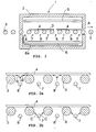
- FIG. 1 schematically shows a sectional side view of a horizontal tempering furnace 1 according to the invention.
- the tempering furnace 1 comprises a housing 2 and rollers 3 upon which glass sheets 4 are placed. During the tempering process, the glass sheets 4 are transferred by means of the rollers 3 in the direction of arrow A.
- a loading table is arranged on the left side of the tempering furnace 1, and a cooling unit for the glass sheets 4 on the right side of the tempering furnace 1. For the sake of clarity, said loading table and cooling unit are not shown in Figure 1.
- the glass sheets 4 are placed on the loading table upon the rollers 3.
- the rollers 3 are typically e.g. ceramic rollers inside the tempering furnace 1 and e.g. metal rollers coated with kevlar band outside the furnace.
- the glass sheets 4 are transferred as one load into a heating chamber confined by the housing 2.
- the glass sheets 4 are typically heated from above with upper resistors 5 and from below with lower resistors 6 in a manner fully known per se.
- a different manner of heating such as forced convection or a combination of different heating manners, is also feasible.
- the temperature of the glass is raised to 610 to 625°C depending on the thickness of the glass.
- the glass sheets 4 undergo a back-and-forth movement, i.e. are oscillated, in a manner fully known per se, for arranging the roller support points evenly upon the entire glass through the entire heating stage. This is a way to minimize deformations in the glass optics caused by uneven support of the glass.
- Cooling pipes 7 are arranged in every second roller gap between the rollers 3 transversely relative to the travel direction of the glass sheet 4. Air at room temperature is typically blown through said cooling pipes 7.
- the pipe serves as a shadow for heat radiation originating from below the glass and also as means for conducting heat out. Heat is transferred to the pipe by convection from the furnace air surrounding it and by direct radiation from near-by surfaces, such as the ceramic rollers 3 and the lower resistors 6 of the furnace. The heat is conveyed through the pipe from the outer surface of the pipe to its inner surface from which it is conveyed by convection into air with which it is removed.
- the temperature of the outer surface of the cooling pipe 7 is kept, if needed, significantly below the temperature of the tempering furnace 1 by means of air flowing through the cooling pipe 7.
- the magnitude of the thermal current transferred to the cooling pipe 7 is easily adjustable by adjusting the speed of the air in the cooling pipe 7.
- the need for cooling changes relative to time, since with the difference in temperature between the glass sheet 4 and the roller 3 becoming smaller, the smaller is the amount of heat to be removed from the tempering furnace 1. This is why the speed of the air is reduced during the entire heating period.
- the effect of a single cooling pipe 7 can be improved by enlarging the diameter of the pipe or by ribbing it.
- Heating pipes 8 are arranged in different roller gaps as compared with the cooling pipes 7, also preferably in every second roller gap. They are provided with machined holes, whereby hot air jets, typically at 650 to 720°C, can be blown from said heating pipe 8 at the lower surface of the glass sheet 4 from between the rollers 3.
- the diameter of the holes in the heating pipe 8 is typically 1 to 2 mm, but may vary even more from case to case.
- the heating pipes 8 are used for heating at the final stage of the heating period when the heating of the glass sheet 4 is typically quite slow, and, in the case of full loads, the ceramic rollers 3 may even start to cool excessively. In these cases, said additional heating at the final stage of the heating period increases the power of the tempering furnace 1. It is obvious that cooling by the cooling pipes 7 and heating by the heating pipes 8 are not employed simultaneously, the system being forced controlled in order to eliminate concomitant operation.
- Figure 1 shows further that the air supplied to the heating pipes 8 arranged between the rollers 3 is led to pass via pipes 8a located below the lower resistors 6. This way the lower resistors 6 make the air warm up in said pipes 8a.
- the lower resistors 6 are allowed to start to cool, but with said solutions the heat remaining in them may, however, still be utilized for heating the heating air.
- Figures 2a and 2b show a sectional side view of a detail of the tempering furnace 1 of Figure 1.
- the numbering of Figures 2a and 2b corresponds to that of Figure 1.
- arrows B show the movement of the air jets blown from the heating pipes 8. If desired, the hot air blown from the heating pipes 8 may also be aimed directly at the rollers 3.
- the cooling pipes 7, too, may be used for blowing air directly at the rollers 3 for cooling the rollers 3 and the part of the tempering furnace 1 below the glass sheet 4. Said current of cooling air is illustrated by arrows C in Figure 2b.
- the solution according to Figures 2a and 2b allow cold air to be blown directly at the rollers 3 at the initial heating stage, whereby the rollers cool down, and hot air to be blown at the final heating stage, whereby the temperature of the rollers 3 may be raised.
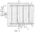
- Figure 3 shows the tempering furnace of the invention from below and in section.
- the numbering of Figure 3 corresponds to that of Figures 1 and 2.
- Figure 3 shows the heating pipes 8 arranged in every second roller gap, but for the sake of clarity does not show the cooling pipes 7, also arranged in every second roller gap, but in different gaps than the heating pipes.
- Hot air is fed to the heating pipes 8 via delivery pipes 9.
- the heating pipes 8 and the delivery pipes 9 are arranged such that hot air is fed to the heating pipes 8 from both sides of the tempering furnace 1 so that air is fed to every second heating pipe 8 from above as seen in Figure 3, and to every second from below. This eliminates the impact of the heat inside the tempering furnace 1 on the temperature of the air passing inside the heating pipes 8.
- the pressure source of the air blown by the heating pipes 8 may be e.g. a compressor 10. After the compressor 10, the air is heated in what is called a heating radiator 11. In the heating radiator 11 the air to be blown is heated in advance to the temperature of the tempering furnace 1, and in some cases even more.
- the heating radiator 11 may be e.g. a chamber in which a combination of pipes and resistors has been built such that the air blown into the furnace is forced to circulate inside the pipes tens of metres in adjacent spirals. In the immediate vicinity of the pipes, preferably in contact with the pipe, are arranged thermal resistors for warming up the pipes and the air inside them to the desired temperature.
- the heating radiator 11 may also be implemented in some other manner fully known per se, and hence the heating radiator 11 is not described in any more detail here. It is essential that the air blown into the tempering furnace 1 can be heated to the desired temperature and that it does not essentially cool down before the tempering furnace 1. In practice this is implemented by providing the heating radiator 11 and the pipes between the heating radiator 11 and the tempering furnace 1 with proper insulation. Further, in connection with the pipes there is a regulator 12 for adjusting the air flow and thus the magnitude of the desired additional heating.
- the pipes further comprise a valve 13 which may be e.g. a magnetic valve. By means of said valve 13 the air flow can be entirely blocked, if desired.
- the cooling pipes are taken in the use, whereby air at room temperature is blown through the cooling pipes 7 arranged between the rollers 3.
- the air warms up when being conveyed across the tempering furnace 1 and carries heat away from the tempering furnace 1 and particularly from the rollers 3.
- the heating of the lower side is entirely or partially switched off.
- the glass load at room temperature is transferred to the tempering furnace 1 where it is oscillated in a reciprocating manner and heated from above and from below.
- the cooling of the lower side is decreased continuously by lowering the speed of the air passing through the cooling pipes 7. At the same time the heating effect of the lower resistors 6 of the tempering furnace 1 is usually increased.
- heating is entirely ceased and direct heating of the lower surface of the glass sheet 4 is initiated by forced convection.
- Direct heating of the lower surface of the glass sheet 4 is increased gradually towards the end of the heating period and simultaneously the heating effect of the lower resistors 6 is increased.
- the glass is transferred to the cooling unit and the direct heat blowing of the lower side is switched off and the cooling pipes are switched on.
- the attached figures do not show e.g. the support structures of the pipes and rollers or the control and rotation means of the rollers, these being known per se to those skilled in the art.
- the rollers 3, for example are shown fewer in number and greater in relation to their natural size.
- cooling pipes and the heating pipes may also be arranged in the same roller gap, and in this case the heating pipe may be arranged above the cooling pipe and fixed to the cooling pipe, for example. In this case the cooling pipes and the heating pipes may be located both in each roller gap.
Landscapes
- Chemical & Material Sciences (AREA)
- Engineering & Computer Science (AREA)
- Materials Engineering (AREA)
- Organic Chemistry (AREA)
- Re-Forming, After-Treatment, Cutting And Transporting Of Glass Products (AREA)
- Joining Of Glass To Other Materials (AREA)
- Tunnel Furnaces (AREA)
- Fertilizers (AREA)
- Furnace Details (AREA)
Claims (12)
- Verfahren zum Erwärmen von Glasplatten in einem mit Rollen versehenen Temperofen, wobei in diesem Verfahren die Glasplatten (4) auf einem Rollenförderer durch dem Temperofen (1) geführt werden, wobei die Glasplatten (4) von oben und von unten her erwärmt werden, wobei die Glasplatten (4) in einer hin- und hergehenden Weise auf den Rollen (3) oszillierend bewegt werden und wobei die Rollen (3) in der Anfangsphase des Erwärmungszeitraums gekühlt werden, dadurch gekennzeichnet, dass in der Endphase des Erwärmungszeitraums die Unterseiten der Glasplatten (4) durch eine Zwangskonvektion erwärmt werden, die durch ein Aufblasen von Heißluftströmen auf diese Glasoberflächen erzielt wird.
- Verfahren nach Anspruch 1, dadurch gekennzeichnet, dass der untere Teil des Temperofens (1) während der Anfangsphase des Erwärmungszeitraums gekühlt wird.
- Verfahren nach Anspruch 1 oder 2, dadurch gekennzeichnet, dass das Kühlen dadurch erfolgt, dass Luft durch Kühlrohre (7) geblasen wird, und dass die Kühleffizienz durch eine Veränderung der Geschwindigkeit der die Kühlrohre (7) passierenden Luft eingestellt wird.
- Verfahren nach einem der vorhergehenden Ansprüche, dadurch gekennzeichnet, dass das Kühlen erfolgt, indem Luft durch Kühlrohre (7) geblasen und die Kühlluft abwechselnd von unterschiedlichen Seiten des Temperofens (1) her zugeführt wird.
- Verfahren nach einem der vorhergehenden Ansprüche, dadurch gekennzeichnet, dass das Erwärmen der Glasplatten (4) durch Zwangskonvektion erfolgt, indem die Zuführung der Luft durch Heizrohre (8) und aus den Rohren (8) heraus derart erfolgt, das die Erwärmungsluft den Rohren (8) abwechselnd von unterschiedlichen Seiten des Temperofens (1) her zugeführt wird.
- Verfahren nach einem der vorhergehenden Ansprüche, dadurch gekennzeichnet, dass das Kühlen des unteren Teils des Temperofens (1) mit Hilfe von Kühlrohren (7) durchgeführt wird, indem die Kühlrohre (7) mit Löchern versehen sind, aus denen Luftströme auf die Rollen (3) geblasen werden, um die Oberflächen der Rollen (3) und den unteren Teil des Temperofens (1) zu kühlen.
- Verfahren nach einem der vorhergehenden Ansprüche, dadurch gekennzeichnet, dass die Zwangskonvektion durchgeführt wird, indem Heißluftströme auf die Unterseite einer Glasplatte (4) aufgeblasen werden, wobei die Temperatur der aufgeblasenen Luft bei 650°C bis 720°C liegt.
- Mit Rollen versehener Temperofen, umfassend Mittel zum Erwärmen der Glassplatten (4) von oben und unten her, horizontale Rollen (3) innerhalb des Temperofens (1), die eine horizontale Glasplatte (4) stützen und für diese einen Förderer bilden, wobei die Rollen (3) so ausgelegt sind, dass sie die Glassplatte (4) während des Erwärmens in einer hin- und hergehenden Weise oszillierend bewegen, sowie Mittel zum Kühlen der Rollen (3) in der Anfangsphase des Erwärmungszeitraums, dadurch gekennzeichnet, dass der Temperofen (1) Mittel zum Erwärmen der Unterseiten der Glasplatten (4) durch Aufblasen von Heißluftströmen auf diese Glasoberflächen umfasst, wodurch eine Zwangskonvektion während der Endphase des Erwärmungszeitraums erzielt wird.
- Temperofen nach Anspruch 8, dadurch gekennzeichnet, dass das Kühlen mit Hilfe von Kühlrohren (7) durchgeführt wird, die in jedem zweiten Rollenspalt vorgesehen sind und durch die Luft aufgeblasen werden kann, und dass das Erwärmen der Unterseiten der Glasplatten (5) durch Zwangskonvektion erfolgt, indem zum Einblasen von Luftströmen ausgelegte Heizrohre (8) so in jedem zweiten Rollenspalt angeordnet sind, dass sich die Kühlrohre (7) und die Heizrohre (8) in unterschiedlichen Rollenspalten befinden.
- Temperofen nach Anspruch 8 oder 9, dadurch gekennzeichnet, dass das Kühlen mit Hilfe von Kühlrohren (7) durchgeführt wird und dass die Kühlrohre (7) so angeordnet sind, dass die durch sie eingeblasene Luft abwechselnd von unterschiedlichen Seiten des Temperofens (1) her eingeblasen wird.
- Temperofen nach Anspruch 9 oder 10, dadurch gekennzeichnet, dass die Kühlrohre (7) mit Löchern versehen sind, die es ermöglichen, dass die Rollen (3) mit Hilfe von durch die Löcher in den Kühlrohren (7) geblasener Luft gekühlt werden.
- Temperofen nach einem der Ansprüche 9 bis 11, dadurch gekennzeichnet, dass der Temperofen (1) Mittel zur Einstellung der Geschwindigkeit der durch die Kühlrohre (7) geblasenen Luft umfasst.
Applications Claiming Priority (3)
| Application Number | Priority Date | Filing Date | Title |
|---|---|---|---|
| FI962158A FI100596B2 (fi) | 1996-05-22 | 1996-05-22 | Menetelmä ja laitteisto lasilevyjen lämmittämiseksi teloilla varustetussa karkaisu-uunissa |
| FI962158 | 1996-05-22 | ||
| PCT/FI1997/000303 WO1997044283A1 (en) | 1996-05-22 | 1997-05-21 | Heating glass sheets in tempering furnace |
Publications (2)
| Publication Number | Publication Date |
|---|---|
| EP0902763A1 EP0902763A1 (de) | 1999-03-24 |
| EP0902763B1 true EP0902763B1 (de) | 2006-08-16 |
Family
ID=8546059
Family Applications (1)
| Application Number | Title | Priority Date | Filing Date |
|---|---|---|---|
| EP97923114A Expired - Lifetime EP0902763B1 (de) | 1996-05-22 | 1997-05-21 | Erwärmung von glastafeln in einem ofen für das tempern |
Country Status (8)
| Country | Link |
|---|---|
| US (1) | US6282923B1 (de) |
| EP (1) | EP0902763B1 (de) |
| JP (1) | JP2000510810A (de) |
| AT (1) | ATE336469T1 (de) |
| AU (1) | AU715773B2 (de) |
| DE (1) | DE69736517T2 (de) |
| FI (1) | FI100596B2 (de) |
| WO (1) | WO1997044283A1 (de) |
Cited By (4)
| Publication number | Priority date | Publication date | Assignee | Title |
|---|---|---|---|---|
| CN102674663A (zh) * | 2012-05-30 | 2012-09-19 | 洛阳兰迪玻璃机器股份有限公司 | 一种异型平板玻璃平钢化方法及系统 |
| EP2551247A1 (de) * | 2011-07-25 | 2013-01-30 | Keraglass Engineering S.R.L. | Brennofen zum Anlassen von Glasplatten |
| CN102964058A (zh) * | 2011-08-31 | 2013-03-13 | 三星康宁精密素材株式会社 | 玻璃钢化方法和装置 |
| CN103819079A (zh) * | 2014-01-03 | 2014-05-28 | 河北省沙河玻璃技术研究院 | 一种低成本铝硅酸盐玻璃在线增强方法 |
Families Citing this family (15)
| Publication number | Priority date | Publication date | Assignee | Title |
|---|---|---|---|---|
| FI109292B (fi) | 1999-11-01 | 2002-06-28 | Uniglass Engineering Oy | Menetelmä ja laitteisto lasin lämmittämiseksi |
| FI110866B (fi) * | 2000-08-28 | 2003-04-15 | Tamglass Ltd Oy | Menetelmä LowE-lasilevyjen lämmittämiseksi karkaisu-uunissa |
| DE60216739T2 (de) * | 2001-03-23 | 2007-10-04 | Glaverbel | Verfahren und vorrichtung zur erhitzung von glasscheiben in einem ofen |
| BE1014065A3 (fr) * | 2001-03-23 | 2003-03-04 | Glaverbel | Procede et dispositif de chauffage de feuilles de verre dans un four. |
| ITMO20020311A1 (it) * | 2002-10-28 | 2004-04-29 | Keraglass Engineering S R L | Forno perfezionato per il riscaldamento di lastre di vetro. |
| FI120451B (fi) * | 2003-06-24 | 2009-10-30 | Uniglass Engineering Oy | Menetelmä ja laitteisto lasin lämmittämiseksi |
| US20090107178A1 (en) * | 2007-10-25 | 2009-04-30 | Jose Ruben Chables Sandoval | Method for manufacturing tempered glass bathroom fixtures |
| DE102008025798C5 (de) * | 2008-05-29 | 2015-08-06 | Guangdong Fushan Glass Machinery Co., Ltd. | Verfahren zum Betreiben eines Rollenofens |
| DE102014102002A1 (de) * | 2013-08-06 | 2015-02-12 | Von Ardenne Gmbh | Substratbehandlungsverfahren |
| EP3109207B1 (de) * | 2015-06-26 | 2018-10-31 | Glaston Finland Oy | Verfahren zum erhitzen einer glasscheibe zur temperierung |
| US9617181B2 (en) | 2015-07-27 | 2017-04-11 | Glaston Finland Oy | Method of heating a glass sheet for tempering |
| CN109502959B (zh) * | 2018-12-12 | 2021-10-26 | 福耀集团(福建)机械制造有限公司 | 一种玻璃压制成型工作台 |
| CN112624584B (zh) * | 2020-12-09 | 2024-08-27 | 江苏金桥玻璃科技有限公司 | 一种具有快速降温功能的钢化玻璃钢化炉 |
| CN115124227B (zh) * | 2022-06-29 | 2024-04-19 | 贵州达沃斯光电有限公司 | 一种钢化玻璃加工用钢化炉装置 |
| CN118619531B (zh) * | 2024-08-09 | 2024-10-25 | 山东晶成玻璃科技有限公司 | 具有导向功能的玻璃钢化炉上料装置及其上料工艺 |
Family Cites Families (12)
| Publication number | Priority date | Publication date | Assignee | Title |
|---|---|---|---|---|
| FI62043C (fi) * | 1980-09-12 | 1982-11-10 | Tamglass Oy | Foerfarande och anordning foer att foerhindra boejningen av glsskivor i en med valsar foersedd ugn i en horisontalhaerd nigsanordning |
| US4505671A (en) | 1981-02-17 | 1985-03-19 | Glasstech, Inc. | Glass sheet roller conveyor furnace including gas jet pump heating |
| US4529380A (en) | 1981-12-22 | 1985-07-16 | Glasstech, Inc. | Glass sheet roller conveyor furnace including gas jet pump heating |
| FI71117C (fi) * | 1984-05-24 | 1986-11-24 | Kyro Oy | Anordning foer utjaemning av temperaturen av transportvalsarnai en glashaerdningsugn |
| US4681616A (en) * | 1985-07-15 | 1987-07-21 | Glasstech, Inc. | Glass sheet tempering method and furnace |
| FI76315C (fi) * | 1986-10-29 | 1988-10-10 | Kyro Oy | Anordning i kylavdelningen till en glashaerdningsanlaeggning. |
| FI83072C (fi) * | 1989-09-06 | 1991-05-27 | Tamglass Oy | Foerfarande och anordning foer att foerhindra boejningen av glasskivor i en med valsar foersedd ugn i en horisontalhaerdningsanordning. |
| FI86407C (fi) * | 1990-12-27 | 1992-08-25 | Tamglass Oy | Foerfarande och anordning foer att utjaemna temperaturprofilen i glasskivor i en med valsar foersedd ugn i en horisontalhaerdningsanordning. |
| FI86406C (fi) * | 1991-01-11 | 1992-08-25 | Tamglass Oy | Anordning foer vaermehaerdning av glasskivor. |
| DE4336364C2 (de) * | 1993-10-25 | 1996-02-29 | Cattin Machines Sa | Vorrichtung zum Erhitzen oder zum Kühlen von tafelförmigem oder bandförmigem Behandlungsgut aus Glas oder keramischem Werkstoff |
| US5672191A (en) * | 1994-06-20 | 1997-09-30 | Gas Research Institute | Forced convection heating apparatus and process for heating glass sheets therewithin |
| FI97378C (fi) | 1995-01-19 | 1996-12-10 | Glassrobots Oy | Menetelmä lämpövaikutusten säätämiseksi ja kohdentamiseksi lasin karkaisu-uunissa ja karkaisu-uuni |
-
1996
- 1996-05-22 FI FI962158A patent/FI100596B2/fi active IP Right Review Request
-
1997
- 1997-05-21 WO PCT/FI1997/000303 patent/WO1997044283A1/en not_active Ceased
- 1997-05-21 DE DE69736517T patent/DE69736517T2/de not_active Expired - Fee Related
- 1997-05-21 JP JP09541672A patent/JP2000510810A/ja active Pending
- 1997-05-21 EP EP97923114A patent/EP0902763B1/de not_active Expired - Lifetime
- 1997-05-21 AU AU29006/97A patent/AU715773B2/en not_active Ceased
- 1997-05-21 US US09/194,193 patent/US6282923B1/en not_active Expired - Fee Related
- 1997-05-21 AT AT97923114T patent/ATE336469T1/de not_active IP Right Cessation
Cited By (7)
| Publication number | Priority date | Publication date | Assignee | Title |
|---|---|---|---|---|
| EP2551247A1 (de) * | 2011-07-25 | 2013-01-30 | Keraglass Engineering S.R.L. | Brennofen zum Anlassen von Glasplatten |
| US9499429B2 (en) | 2011-07-25 | 2016-11-22 | Keraglass Industries S.R.L. | Kiln for annealing glass slabs |
| CN102964058A (zh) * | 2011-08-31 | 2013-03-13 | 三星康宁精密素材株式会社 | 玻璃钢化方法和装置 |
| CN102674663A (zh) * | 2012-05-30 | 2012-09-19 | 洛阳兰迪玻璃机器股份有限公司 | 一种异型平板玻璃平钢化方法及系统 |
| CN102674663B (zh) * | 2012-05-30 | 2014-05-28 | 洛阳兰迪玻璃机器股份有限公司 | 一种异型平板玻璃平钢化方法及系统 |
| CN103819079A (zh) * | 2014-01-03 | 2014-05-28 | 河北省沙河玻璃技术研究院 | 一种低成本铝硅酸盐玻璃在线增强方法 |
| CN103819079B (zh) * | 2014-01-03 | 2016-01-27 | 河北省沙河玻璃技术研究院 | 一种低成本铝硅酸盐玻璃在线增强方法 |
Also Published As
| Publication number | Publication date |
|---|---|
| DE69736517T2 (de) | 2007-02-08 |
| FI962158L (fi) | 1997-11-23 |
| US6282923B1 (en) | 2001-09-04 |
| DE69736517D1 (de) | 2006-09-28 |
| JP2000510810A (ja) | 2000-08-22 |
| AU715773B2 (en) | 2000-02-10 |
| FI100596B2 (fi) | 2002-09-10 |
| EP0902763A1 (de) | 1999-03-24 |
| FI962158A0 (fi) | 1996-05-22 |
| ATE336469T1 (de) | 2006-09-15 |
| FI100596B (fi) | 1998-01-15 |
| AU2900697A (en) | 1997-12-09 |
| WO1997044283A1 (en) | 1997-11-27 |
Similar Documents
| Publication | Publication Date | Title |
|---|---|---|
| EP0902763B1 (de) | Erwärmung von glastafeln in einem ofen für das tempern | |
| WO1997044283A9 (en) | Heating glass sheets in tempering furnace | |
| US6881931B2 (en) | Method and apparatus for heating glass | |
| US7290405B2 (en) | Method and apparatus for conducting heat to a glass sheet | |
| EP1298096B1 (de) | Verfahren und Vorrichtung zum Erwärmen von Glastafeln vor dem Tempern | |
| EP0564489B1 (de) | Verfahren und vorrichtung zum egalisieren des temperaturprofils von glasscheiben in einem rollenofen in einem horizontalen ausglühofen | |
| TWI850351B (zh) | 用於玻璃板之回火爐 | |
| AU715776B2 (en) | Heating glass in tempering furnace | |
| WO1998003439A1 (en) | A method for adjusting and directing heat effects in a glass tempering oven and an oven | |
| FI83072C (fi) | Foerfarande och anordning foer att foerhindra boejningen av glasskivor i en med valsar foersedd ugn i en horisontalhaerdningsanordning. | |
| EP1048622B1 (de) | Vorrichtung und Verfahren zur Verringerung von Kratzern während des Biegens von Glasscheiben | |
| US4057411A (en) | Heat treating glass sheets on a roller hearth conveyor | |
| FI111006B (fi) | Menetelmä lämmön johtamiseksi lasiin | |
| US4311507A (en) | Special entrance slit module and method for quenching glass sheets | |
| CN100478460C (zh) | 减少热处理时金属带形成的褶皱的方法 | |
| JPS6214009B2 (de) | ||
| JP2001311585A (ja) | 徐冷設備 | |
| JPH10287437A (ja) | 加熱炉 | |
| EP0932585A1 (de) | Verfahren zum regeln und rivhten von heizeffekte in einer glashärteofen und dafür benötigte ofen |
Legal Events
| Date | Code | Title | Description |
|---|---|---|---|
| PUAI | Public reference made under article 153(3) epc to a published international application that has entered the european phase |
Free format text: ORIGINAL CODE: 0009012 |
|
| 17P | Request for examination filed |
Effective date: 19981204 |
|
| AK | Designated contracting states |
Kind code of ref document: A1 Designated state(s): AT CH DE FR GB IT LI |
|
| 17Q | First examination report despatched |
Effective date: 20010313 |
|
| GRAP | Despatch of communication of intention to grant a patent |
Free format text: ORIGINAL CODE: EPIDOSNIGR1 |
|
| GRAS | Grant fee paid |
Free format text: ORIGINAL CODE: EPIDOSNIGR3 |
|
| GRAA | (expected) grant |
Free format text: ORIGINAL CODE: 0009210 |
|
| AK | Designated contracting states |
Kind code of ref document: B1 Designated state(s): AT CH DE FR GB IT LI |
|
| PG25 | Lapsed in a contracting state [announced via postgrant information from national office to epo] |
Ref country code: IT Free format text: LAPSE BECAUSE OF FAILURE TO SUBMIT A TRANSLATION OF THE DESCRIPTION OR TO PAY THE FEE WITHIN THE PRESCRIBED TIME-LIMIT;WARNING: LAPSES OF ITALIAN PATENTS WITH EFFECTIVE DATE BEFORE 2007 MAY HAVE OCCURRED AT ANY TIME BEFORE 2007. THE CORRECT EFFECTIVE DATE MAY BE DIFFERENT FROM THE ONE RECORDED. Effective date: 20060816 |
|
| REG | Reference to a national code |
Ref country code: GB Ref legal event code: FG4D |
|
| REG | Reference to a national code |
Ref country code: CH Ref legal event code: EP |
|
| REF | Corresponds to: |
Ref document number: 69736517 Country of ref document: DE Date of ref document: 20060928 Kind code of ref document: P |
|
| REG | Reference to a national code |
Ref country code: CH Ref legal event code: NV Representative=s name: FREI PATENTANWALTSBUERO |
|
| PGFP | Annual fee paid to national office [announced via postgrant information from national office to epo] |
Ref country code: AT Payment date: 20070405 Year of fee payment: 11 |
|
| PGFP | Annual fee paid to national office [announced via postgrant information from national office to epo] |
Ref country code: CH Payment date: 20070413 Year of fee payment: 11 |
|
| PGFP | Annual fee paid to national office [announced via postgrant information from national office to epo] |
Ref country code: DE Payment date: 20070425 Year of fee payment: 11 |
|
| PLBE | No opposition filed within time limit |
Free format text: ORIGINAL CODE: 0009261 |
|
| STAA | Information on the status of an ep patent application or granted ep patent |
Free format text: STATUS: NO OPPOSITION FILED WITHIN TIME LIMIT |
|
| 26N | No opposition filed |
Effective date: 20070518 |
|
| PGFP | Annual fee paid to national office [announced via postgrant information from national office to epo] |
Ref country code: GB Payment date: 20070412 Year of fee payment: 11 |
|
| PGFP | Annual fee paid to national office [announced via postgrant information from national office to epo] |
Ref country code: IT Payment date: 20070521 Year of fee payment: 11 |
|
| PGFP | Annual fee paid to national office [announced via postgrant information from national office to epo] |
Ref country code: FR Payment date: 20070411 Year of fee payment: 11 |
|
| REG | Reference to a national code |
Ref country code: CH Ref legal event code: PL |
|
| GBPC | Gb: european patent ceased through non-payment of renewal fee |
Effective date: 20080521 |
|
| PG25 | Lapsed in a contracting state [announced via postgrant information from national office to epo] |
Ref country code: LI Free format text: LAPSE BECAUSE OF NON-PAYMENT OF DUE FEES Effective date: 20080531 Ref country code: CH Free format text: LAPSE BECAUSE OF NON-PAYMENT OF DUE FEES Effective date: 20080531 |
|
| PG25 | Lapsed in a contracting state [announced via postgrant information from national office to epo] |
Ref country code: AT Free format text: LAPSE BECAUSE OF NON-PAYMENT OF DUE FEES Effective date: 20080521 |
|
| REG | Reference to a national code |
Ref country code: FR Ref legal event code: ST Effective date: 20090119 |
|
| PG25 | Lapsed in a contracting state [announced via postgrant information from national office to epo] |
Ref country code: FR Free format text: LAPSE BECAUSE OF NON-PAYMENT OF DUE FEES Effective date: 20080602 Ref country code: DE Free format text: LAPSE BECAUSE OF NON-PAYMENT OF DUE FEES Effective date: 20081202 |
|
| PG25 | Lapsed in a contracting state [announced via postgrant information from national office to epo] |
Ref country code: GB Free format text: LAPSE BECAUSE OF NON-PAYMENT OF DUE FEES Effective date: 20080521 |
|
| PG25 | Lapsed in a contracting state [announced via postgrant information from national office to epo] |
Ref country code: IT Free format text: LAPSE BECAUSE OF NON-PAYMENT OF DUE FEES Effective date: 20080521 |