EP0902751B1 - Process for venting a hydraulic assisted steering system - Google Patents
Process for venting a hydraulic assisted steering system Download PDFInfo
- Publication number
- EP0902751B1 EP0902751B1 EP96922808A EP96922808A EP0902751B1 EP 0902751 B1 EP0902751 B1 EP 0902751B1 EP 96922808 A EP96922808 A EP 96922808A EP 96922808 A EP96922808 A EP 96922808A EP 0902751 B1 EP0902751 B1 EP 0902751B1
- Authority
- EP
- European Patent Office
- Prior art keywords
- hydraulic
- resonator
- valve
- oil
- air
- Prior art date
- Legal status (The legal status is an assumption and is not a legal conclusion. Google has not performed a legal analysis and makes no representation as to the accuracy of the status listed.)
- Expired - Lifetime
Links
Images
Classifications
-
- B—PERFORMING OPERATIONS; TRANSPORTING
- B62—LAND VEHICLES FOR TRAVELLING OTHERWISE THAN ON RAILS
- B62D—MOTOR VEHICLES; TRAILERS
- B62D5/00—Power-assisted or power-driven steering
- B62D5/06—Power-assisted or power-driven steering fluid, i.e. using a pressurised fluid for most or all the force required for steering a vehicle
- B62D5/062—Details, component parts
-
- F—MECHANICAL ENGINEERING; LIGHTING; HEATING; WEAPONS; BLASTING
- F15—FLUID-PRESSURE ACTUATORS; HYDRAULICS OR PNEUMATICS IN GENERAL
- F15B—SYSTEMS ACTING BY MEANS OF FLUIDS IN GENERAL; FLUID-PRESSURE ACTUATORS, e.g. SERVOMOTORS; DETAILS OF FLUID-PRESSURE SYSTEMS, NOT OTHERWISE PROVIDED FOR
- F15B21/00—Common features of fluid actuator systems; Fluid-pressure actuator systems or details thereof, not covered by any other group of this subclass
- F15B21/04—Special measures taken in connection with the properties of the fluid
Definitions
- the present invention relates to a hydraulic power steering system and a Process for venting it with oil release volumes.
- DE 35 38 670 a valve-controlled ventilation Automotive cooler.
- DE 19 01 776 describes a device for automatic venting of hydraulic systems using a spring-loaded Piston / cylinder arrangement known.
- DE 41 20 665 discloses one Hydraulic pump driven by an electric motor, characterized by a compact and installation-friendly design.
- DE 40 40 003 discloses one Power steering for vehicles, with expansion tank only on the edge Ventilation are described, which are so-called air separator elements, too which have direct hydraulic lines.
- DE 24 06 565 relates to a Power steering with a vent in the form of a spring-loaded ball is trained.
- DE 43 26 580 discloses a device for Degassing a hydraulic system, which is an additional component in the form proposes a drum-shaped separator in the area of the storage container.
- servo steering systems of the generic type kind known in which from a servo pump a pressure medium, usually Hydraulic oil, via a power steering valve in the chambers of a hydraulic Steering gear is guided.
- a pressure medium usually Hydraulic oil
- So-called air accumulations occur, which are undesirable and sometimes unpleasant tax results.
- so-called oil expansion volumes are formed in hydraulic systems, for example if resonators are used. The air can open up different ways arise, for example by leakage, by Elimination from the print medium and the like.
- Oil release volumes for example the resonator
- the Oil release volumes have a dome, in which air can collect because the dome is in the installed position upwards points, a lot of air will collect in the dome over time and lead to severe disruptions due to foaming and a consequent Increased wear on the pump.
- the present invention is based on the object of specifying a method for reducing air inclusions.
- the invention is intended to provide a hydraulic power steering system which, with reduced air proportions, does not have the disadvantages that are generated by air pockets.
- the invention proposes a hydraulic power steering system with at least one oil expansion volume in the form of a resonator arranged on a hydraulic pump, which in the upper region in the installed position has a connection to a tank volume, which is produced by a valve which is directly connected to protrudes the tank, and which is used at the same time as a vent and as a suction valve.
- the Invention uses a connecting line.
- the connecting line is realized by a valve or has one.
- the invention can be particularly advantageous in the case of a hydraulic one Use a power steering system in which a resonator is integrated.
- the resonator is a Volume element, which has a plurality of chambers, the Pressure pulsation of the hydraulic oil in the resonator is reduced. It is known that directly in an upper area of the hydraulic pump the resonator is arranged.
- a tank usually a plastic part, surrounds both part of the pump as well as the resonator.
- a valve in the upper region of the resonator or a relaxation volume arranged a valve.
- This valve opens according to an advantageous proposal of the invention depending on the pressure.
- This pressure-dependent opening / closing valve protrudes according to an advantageous one Proposal of the invention directly in the tank. So it gathers within the Resonators with time air, it becomes dependent on the hydraulic pressure regularly in an open system, i.e. the tank is discharged.
- valve according to the invention a previously provided on a hydraulic pump Valve with originally different function replaced.
- the air can collect in a hydraulic system in different ways. First of all, this can be done when filling a pump or when refilling the system done during operation. It is also known that, for example, by Cavitation, chemical decomposition, leakage and the like can arise in a hydraulic system.
- the air is through the regular Oil volume flow not conveyed out of the system. It gathers in top Volume ranges, for example in a resonator cover. This especially when the resonator cover is dome-shaped. The one in the system Any remaining air foams the extracted oil. This worsens it Noise behavior and can tear off the lubricating film in the pump and thus reduce the lifespan.
- the valve is closed and guaranteed at higher pressures thus the normal operation of the pump and resonator.
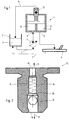
- FIG. 1 shows a hydraulic system 1, in which in a tank 2 Hydraulic oil 3 is added.
- the oil 3 of a pump 5 is fed via a line 4 supplied, the amount of oil via a valve, not shown, a steering gear 6 is supplied.
- the oil finally comes back in via a line 7 the tank 2.
- Embodiment 8 Is shown between the pump 5 and the steering gear 6 in Embodiment arranged a resonator 8.
- Chambers 10, 11 are in the resonator 8 formed so that the oil leaves the resonator through the bore 12.
- the resonator 8 serves to reduce pressure pulsations.
- valve 13 arranged in the dome of the resonator 8, in Depending on the specified parameters, accumulated air via the line 14 are returned to tank 2.
- the operating parameters according to which Valve 13 opens or closes, can be set as desired.
- a suitable one The parameter is the hydraulic pressure.
- the resonator In modern and known pumps, the resonator is directly on the Pump attached. In this case a hole from the pump leads directly into the Resonator. The hydraulic oil then passes through different chambers and arrives via another hole in the further circuit. In the shown The embodiment is the inlet bore in the resonator 8, the bore 9. Das Hydraulic oil passes through several chambers 10, 11 and leaves the resonator via the Hole 12.
- FIG. 13 An exemplary embodiment of a valve 13 is shown in FIG.
- the valve 13 has a through hole in which a spring 16 in a spring chamber 15 is arranged.
- the spring 16 is a in the embodiment shown Coil spring, which pressed a ball 17 against a locking cam 18
- the valve 13 is open for suction. From a given pressure the ball 17 pressed against the force of the spring 16 by the cam 18 and against the sealing seat 20 closed.
- the valve 13 is of a type known per se.
- the Air that can be foamed with oil or can have oil leaves the Resonator via valve 13 and connection 19 in an open system, for example tank 2.
Landscapes
- Engineering & Computer Science (AREA)
- Chemical & Material Sciences (AREA)
- Mechanical Engineering (AREA)
- Analytical Chemistry (AREA)
- Physics & Mathematics (AREA)
- Fluid Mechanics (AREA)
- General Engineering & Computer Science (AREA)
- Combustion & Propulsion (AREA)
- Transportation (AREA)
- Fluid-Pressure Circuits (AREA)
- Power Steering Mechanism (AREA)
Description
Die vorliegende Erfindung betrifft ein Hydraulik-Servolenksystem sowie ein Verfahren zu dessen Entlüftung mit Ölentspannungsvolumina.The present invention relates to a hydraulic power steering system and a Process for venting it with oil release volumes.
Verschiedenartige Vorrichtungen zum Be- und Entlüften von flüssigkeitsbeinhaltenden Behältern sowie insbesondere zum Entgasen von Hydraulikanlagen sind aus dem Stand der Technik bekannt. So offenbart beispielsweise die DE 35 38 670 eine ventilgesteuerte Be- und Entlüftung eines Kfz-Kühlers. Aus der DE 19 01 776 ist eine Vorrichtung zum selbsttätigen Entlüften von Hydraulikanlagen unter Verwendung einer federbelasteten Kolben/Zylinderanordnung bekannt. Die DE 41 20 665 offenbart eine elektromotorisch angetriebene Hydraulikpumpe, die sich durch eine kompakte und montagefreundliche Bauweise auszeichnet. Die DE 40 40 003 offenbart eine Servolenkung für Fahrzeuge, wobei nur am Rande Ausgleichsbehälter mit Entlüftung beschrieben sind, die sogenannte Luftabscheiderelemente sind, zu denen direkte Hydraulikleitungen geführt sind. Die DE 24 06 565 betrifft eine Hilfskraftlenkung mit einer Entlüftung, die in Form einer federbelasteten Kugel ausgebildet ist. Schließlich offenbart die DE 43 26 580 eine Vorrichtung zum Entgasen eines hydraulischen Systems, welches ein zusätzliches Bauteil in Form eines trommelförmigen Separators im Bereich des Vorratsbehälters vorschlägt.Various devices for the ventilation of Containers containing liquids and in particular for degassing Hydraulic systems are known from the prior art. So revealed For example, DE 35 38 670 a valve-controlled ventilation Automotive cooler. DE 19 01 776 describes a device for automatic venting of hydraulic systems using a spring-loaded Piston / cylinder arrangement known. DE 41 20 665 discloses one Hydraulic pump driven by an electric motor, characterized by a compact and installation-friendly design. DE 40 40 003 discloses one Power steering for vehicles, with expansion tank only on the edge Ventilation are described, which are so-called air separator elements, too which have direct hydraulic lines. DE 24 06 565 relates to a Power steering with a vent in the form of a spring-loaded ball is trained. Finally, DE 43 26 580 discloses a device for Degassing a hydraulic system, which is an additional component in the form proposes a drum-shaped separator in the area of the storage container.
Ebenfalls sind im Stand der Technik Servo-Lenksysteme der gattungsgemäßen Art bekannt, bei welchen von einer Servopumpe ein Druckmedium, meist Hydrauliköl, über ein Servolenkventil in die Kammern eines hydraulischen Lenkgetriebes geführt wird. Einerseits ist es bekannt, daß in Hydrauliksystemen sogenannte Luftansammlungen auftreten, welche zu ungewünschten und zum Teil unangenehmen Steuerergebnissen führen können. Andererseits ist es bekannt, daß in Hydrauliksystemen sogenannte Ölentspannungsvolumina gebildet werden, beispielsweise wenn Resonatoren eingesetzt werden. Die Luft kann dabei auf unterschiedliche Weise entstehen, beispielsweise durch Leckage, durch Ausscheiden aus dem Druckmedium und dergleichen. Insbesondere wenn die Ölentspannungsvolumina, beispielsweise der Resonator, eine Kuppel aufweisen, in welcher sich Luft ansammeln kann, weil die Kuppel in Einbaulage nach oben weist, wird sich in der Kuppel mit der Zeit entsprechend viel Luft ansammeln und zu starken Störungen infolge Verschäumung führen und einer daraus folgenden Verschleißerhöhung der Pumpe.Also in the prior art are servo steering systems of the generic type Kind known in which from a servo pump a pressure medium, usually Hydraulic oil, via a power steering valve in the chambers of a hydraulic Steering gear is guided. On the one hand, it is known that in hydraulic systems So-called air accumulations occur, which are undesirable and sometimes unpleasant tax results. On the other hand, it is known that so-called oil expansion volumes are formed in hydraulic systems, for example if resonators are used. The air can open up different ways arise, for example by leakage, by Elimination from the print medium and the like. Especially when the Oil release volumes, for example the resonator, have a dome, in which air can collect because the dome is in the installed position upwards points, a lot of air will collect in the dome over time and lead to severe disruptions due to foaming and a consequent Increased wear on the pump.
Es besteht somit ein Bedarf daran, Maßnahmen zur Reduzierung der eingeschlossenen Luftmengen zu ergreifen.There is therefore a need to take measures to reduce the trapped air volumes.
Davon ausgehend liegt der vorliegenden Erfindung die Aufgabe zugrunde, ein Verfahren zur Reduzierung von Lufteinschlüssen anzugeben. Darüber hinaus soll mit der Erfindung ein hydraulisches Servolenksystem angegeben werden, welches bei reduzierten Luftanteilen die Nachteile, die durch Lufteinschlüsse erzeugt werden, nicht aufweist.Proceeding from this, the present invention is based on the object of specifying a method for reducing air inclusions. In addition, the invention is intended to provide a hydraulic power steering system which, with reduced air proportions, does not have the disadvantages that are generated by air pockets.
Zur technischen Lösung dieser Aufgabe wird mit der Erfindung vorgeschlagen ein Hydraulik-Servolenksystem mit wenigstens einem Ölentspannungsvolumen in Form eines an einer Hydraulikpumpe angeordneten Resonators, welcher im in Einbaulage oberen Bereich eine Verbindung zu einem Tankvolumen aufweist, die durch ein Ventil hergestellt ist, welches direkt in den Tank ragt, und welches gleichzeitig als Entlüftungs- und als Nachsaugventil eingesetzt ist.To solve this problem technically, the invention proposes a hydraulic power steering system with at least one oil expansion volume in the form of a resonator arranged on a hydraulic pump, which in the upper region in the installed position has a connection to a tank volume, which is produced by a valve which is directly connected to protrudes the tank, and which is used at the same time as a vent and as a suction valve.
Bei dieser erfindungsgemäßen Lösung besteht nunmehr die Möglichkeit, die Luft, die sich innerhalb der Kuppel gesammelt hat, in ein offenes System abzuführen. Das offene System wird dabei durch ein Tankvolumen realisiert. Andere Realisierungen sind denkbar und liegen im Rahmen der Erfindung. Dabei ist vorgesehen, daß die Verbindung der beiden Volumina in vorteilhafter Weise von Betriebsparametern abhängt. Ein geeigneter Betriebsparameter ist dabei der Hydraulikdruck. With this solution according to the invention there is now the possibility of that has accumulated within the dome can be discharged into an open system. The open system is realized with a tank volume. Other Realizations are conceivable and are within the scope of the invention. It is provided that the connection of the two volumes in an advantageous manner from Operating parameters depends. A suitable operating parameter is the Hydraulic pressure.
Somit wird also bei einem gegebenen Hydraulikdruck eine Verbindung erzeugt, so daß die in einem Entspannungsvolumen gesammelte Luft in ein offenes System abgeführt werden kann. Hierzu wird gemäß einem vorteilhaften Vorschlag der Erfindung eine Verbindungsleitung verwendet. In besonders vorteilhafter Weise wird die Verbindungsleitung durch ein Ventil realisiert oder weist ein solches auf.Thus, a connection is created at a given hydraulic pressure, so that the air collected in a relaxation volume is in an open system can be dissipated. According to an advantageous proposal, the Invention uses a connecting line. In a particularly advantageous way the connecting line is realized by a valve or has one.
Mit der Erfindung wird ein einfaches und mit geringem wirtschaftlichen Aufwand zu realisierendes Verfahren bereitgestellt, mit welchem Lufteinschlüsse weitestgehend vermieden werden können.With the invention is a simple and with little economic effort Realizing method provided with which air pockets can be largely avoided.
Wird bei einem hydraulischen Servolenksystem das erfindungsgemäße Verfahren angewandt, ergibt sich ein neuartiges Servolenksystem mit einem Ölentspannungsvolumen, welches mit seinem in Einbaulage oberen Bereich eine Verbindung zu einem offenen System, vorzugsweise einem Tankvolumen aufweist.In a hydraulic power steering system, the method according to the invention applied, there is a new type of power steering system with one Oil expansion volume, which with its upper area in the installation position Connection to an open system, preferably a tank volume having.
Mit besonderen Vorteil läßt sich die Erfindung bei einem hydraulischen Servolenksystem anwenden, in welches ein Resonator integriert ist.The invention can be particularly advantageous in the case of a hydraulic one Use a power steering system in which a resonator is integrated.
Besondere Vorteile ergeben sich bei Lenksystemen, bei welchen direkt an der Hydraulikpumpe ein Resonator angeordnet ist. Der Resonator ist ein Volumenelement, welches eine Vielzahl von Kammern auf weist, wobei sich die Druckpulsation des Hydrauliköls im Resonator vermindert. Dabei ist es bekannt, daß direkt in einem oberen Bereich der Hydraulikpumpe der Resonator angeordnet ist. Ein Tank, in der Regel ein Kunststoff-Teil, umgibt dabei sowohl einen Teil der Pumpe als auch den Resonator.There are special advantages with steering systems, in which directly on the Hydraulic pump a resonator is arranged. The resonator is a Volume element, which has a plurality of chambers, the Pressure pulsation of the hydraulic oil in the resonator is reduced. It is known that directly in an upper area of the hydraulic pump the resonator is arranged. A tank, usually a plastic part, surrounds both part of the pump as well as the resonator.
In besonders vorteilhafter Weise ist in dem oberen Bereich des Resonator bzw. eines Entspannungsvolumens ein Ventil angeordnet. Dieses Ventil öffnet gemäß einem vorteilhaften Vorschlag der Erfindung druckabhängig.In a particularly advantageous manner, in the upper region of the resonator or a relaxation volume arranged a valve. This valve opens according to an advantageous proposal of the invention depending on the pressure.
Dieses druckabhängig öffnende/schließende Ventil ragt gemäß einem vorteilhaften Vorschlag der Erfindung direkt in den Tank. Sammelt sich somit innerhalb des Resonators mit der Zeit Luft, so wird diese in Abhängigkeit vom Hydraulikdruck regelmäßig in ein offenes System, das heißt den Tank abgeführt. This pressure-dependent opening / closing valve protrudes according to an advantageous one Proposal of the invention directly in the tank. So it gathers within the Resonators with time air, it becomes dependent on the hydraulic pressure regularly in an open system, i.e. the tank is discharged.
Gemäß einem besonders vorteilhaften Vorschlag der Erfindung kann dabei vorgesehen sein, daß das zum Auslassen angesammelter Luft vorgesehene neue und erfindungsgemäße Ventil ein bisher an einer Hydraulikpumpe vorgesehenes Ventil mit ursprünglich anderer Funktion ersetzt.According to a particularly advantageous proposal of the invention be provided that the new air to be discharged is provided and valve according to the invention a previously provided on a hydraulic pump Valve with originally different function replaced.
Die Luft kann sich in einem Hydrauliksystem auf unterschiedliche Arten sammeln. Zunächst kann dies beim Befüllen einer Pumpe oder beim Nachfüllen des Systems während des Betriebs erfolgen. Auch ist es bekannt, daß beispielsweise durch Kavitation, Auslösen durch chemische Zersetzung, Leckage und dergleichen Luft in einem Hydrauliksystem entstehen kann. Die Luft wird durch den regulären Ölvolumenstrom nicht aus dem System gefördert. Sie sammelt sich in oberen Volumenbereichen an, beispielsweise in einem Resonatordeckel. Dies besonders dann, wenn der Resonatordeckel kuppelartig ausgestaltet ist. Die im System verbleibende Luft verschäumt das geförderte Öl. Dies verschlechtert das Geräuschverhalten und kann zum Abreißen des Schmierfilms in der Pumpe führen und somit die Lebensdauer verringern.The air can collect in a hydraulic system in different ways. First of all, this can be done when filling a pump or when refilling the system done during operation. It is also known that, for example, by Cavitation, chemical decomposition, leakage and the like can arise in a hydraulic system. The air is through the regular Oil volume flow not conveyed out of the system. It gathers in top Volume ranges, for example in a resonator cover. This especially when the resonator cover is dome-shaped. The one in the system Any remaining air foams the extracted oil. This worsens it Noise behavior and can tear off the lubricating film in the pump and thus reduce the lifespan.
Bei der erfindungsgemäßen Verfahrensweise gewährleistet beispielsweise ein Entlüftungsventil, welches bei geringen Drücken, zum Beispiel p = 2 bar, geöffnet ist, einen schwachen Leckagestrom zurück in ein offenes System, beispielsweise einen Tank. Bei größeren Drücken ist das Ventil geschlossen und gewährleistet damit den normalen Betrieb von Pumpe und Resonator.In the procedure according to the invention, for example, a Vent valve which opens at low pressures, for example p = 2 bar is, a weak leakage flow back into an open system, for example a tank. The valve is closed and guaranteed at higher pressures thus the normal operation of the pump and resonator.
Hieraus ergeben sich eine Reihe von Vorteilen. Einerseits wird das System im Stand-By-Modus des Motor-Pumpen-Aggregats ständig entlüftet. Zum anderen verringert der geringere Volumenstrom durch das Lenkgetriebe den Systemdruck und damit den Energieverbrauch im Stand-By-Betrieb. Bei nur 0,5 1/min Leckage ergeben sich Einsparungen von ca. 5 bis 7%. Schließlich verbessert sich durch den niedrigeren Systemdruck das Rücklaufverhalten des Lenkgetriebes.This has a number of advantages. On the one hand, the system in Stand-by mode of the motor-pump unit is constantly vented. On the other hand The lower volume flow through the steering gear reduces the system pressure and thus the energy consumption in stand-by mode. With only 0.5 1 / min leakage savings of approx. 5 to 7% result. Finally improves through the lower system pressure the return behavior of the steering gear.
Weitere Vorteile und Merkmale der Erfindung ergeben sich aus der folgenden Beschreibung anhand der Figuren. Dabei zeigen:
- Fig. 1
- eine schematische Darstellung eines hydraulischen Steuerkreises gemäß einem Ausführungsbeispiel der Erfindung und
- Fig. 2
- einen Schnittdarstellung eines Ausführungsbeispiels für ein Ventil.
- Fig. 1
- is a schematic representation of a hydraulic control circuit according to an embodiment of the invention and
- Fig. 2
- a sectional view of an embodiment of a valve.
In Figur 1 ist ein Hydrauliksystem 1 gezeigt, bei welchen in einem Tank 2
Hydrauliköl 3 aufgenommen ist. Über eine Leitung 4 wird das Öl 3 einer Pumpe 5
zugeführt, wobei die Ölmenge über ein nicht gezeigtes Ventil einem Lenkgetriebe
6 zugeführt wird. Über eine Leitung 7 gelangt das Öl schließlich wieder zurück in
den Tank 2.1 shows a hydraulic system 1, in which in a
Zwischen der Pumpe 5 und dem Lenkgetriebe 6 ist im gezeigten
Ausführungsbeispiel ein Resonator 8 angeordnet. In dem Resonator 8 wird das Öl
über die Bohrung 9 zugeführt. In dem Resonator 8 sind Kammern 10, 11
ausgebildet, so daß das Öl über die Bohrung 12 den Resonator wieder verläßt.
Der Resonator 8 dient dabei der Reduzierung von Druckpulsationen.Is shown between the
Während des Befüllens bzw. nach dem Füllen einer Pumpe mit Resonator, gegebenenfalls auch während des Betriebs infolge von Kavitation, Auslösen von Luft durch chemische Zersetzung, Leckage oder dergleichen, reichert sich in dem Resonatordeckel Luft an. Dies wird begünstigt dadurch, daß der Resonator einen kuppelartigen Deckel aufweist. Die gesammelte Luft wird durch den regulären Ölvolumenstrom nicht vollständig aus dem Resonator gefördert. Die im System verbleibende Luft verschäumt das geforderte Öl. Dies verschlechtert das Geräuschverhalten und kann zum Abreißen des Schmierfilms in der Pumpe führen.While filling or after filling a pump with a resonator, possibly also during operation due to cavitation, triggering of Air through chemical decomposition, leakage or the like accumulates in the Resonator cover air on. This is favored by the fact that the resonator has a has dome-like cover. The air collected is regulated by the regular Oil volume flow not completely conveyed out of the resonator. The one in the system Any remaining air foams the required oil. This worsens it Noise behavior and can tear off the lubricating film in the pump to lead.
Durch das in der Kuppel des Resonators 8 angeordnete Ventil 13 kann in
Abhängigkeit von vorgegebenen Parameter angesammelte Luft über die Leitung
14 in den Tank 2 zurückgeführt werden. Die Betriebsparameter, nach denen das
Ventil 13 öffnet bzw. schließt, lassen sich beliebig festlegen. Ein geeigneter
Parameter ist der Hydraulikdruck. Das Ventil 13 kann so ausgelegt werden, daß es
bei geringen Drücken geöffnet ist. So kann vorgesehen sein, daß das Ventil 13 bei
geringen Drücken, beispielsweise p = 2 bar, einen Leckagestrom in den Tank 2
gewährleistet, beispielsweise Q = 0,5 bis 1 Liter/Minute. Bei Drücken > 2 bar ist
das Ventil 13 geschlossen und gewährleistet damit den normalen Betrieb von
Pumpe 5 und Resonator 8. Through the
Bei modernen und an sich bekannten Pumpen ist der Resonator direkt an der
Pumpe befestigt. In diesem Fall führt eine Bohrung von der Pumpe direkt in den
Resonator. Das Hydrauliköl durchläuft dann verschiedene Kammern und gelangt
über eine weitere Bohrung in den weiteren Kreislauf. Im gezeigten
Ausführungsbeispiel ist die Zulaufbohrung in den Resonator 8 die Bohrung 9. Das
Hydrauliköl durchläuft einige Kammern 10, 11 und verläßt den Resonator über die
Bohrung 12.In modern and known pumps, the resonator is directly on the
Pump attached. In this case a hole from the pump leads directly into the
Resonator. The hydraulic oil then passes through different chambers and arrives
via another hole in the further circuit. In the shown
The embodiment is the inlet bore in the
In Figur 2 ist ein Ausführungsbeispiel für ein Ventil 13 gezeigt. Das Ventil 13 hat
eine Durchgangsbohrung, in welcher in einem Federraum 15 eine Feder 16
angeordnet ist. Die Feder 16 ist im gezeigten Ausführungsbeispiel eine
Schraubenfeder, welche eine Kugel 17 gegen einen Rastnocken 18 drückte Somit
ist das Ventil 13 zum Nachsaugen geöffnet. Ab einem vorgegebenen Druck wird
die Kugel 17 gegen die Kraft der Feder 16 vom Nocken 18 abgedrückt und gegen
den Dichtsitz 20 geschlossen. Das Ventil 13 ist von an sich bekannter Bauart. Die
Luft, welche mit Öl verschäumt sein kann oder Öl aufweisen kann, verläßt den
Resonator über das Ventil 13 und den Anschluß 19 in ein offenes System,
beispielsweise den Tank 2. An exemplary embodiment of a
- 11
- HydrauliksystemHydraulic system
- 22nd
- Tanktank
- 33rd
- HydraulikölHydraulic oil
- 44th
- Leitungmanagement
- 55
- Pumpepump
- 66
- LenkgetriebeSteering gear
- 77
- Leitungmanagement
- 88th
- ResonatorResonator
- 99
- Bohrungdrilling
- 1010th
- Kammerchamber
- 1111
- Kammerchamber
- 1212th
- Bohrungdrilling
- 1313
- VentilValve
- 1414
- Leitungmanagement
- 1515
- FederraumSpring chamber
- 1616
- Federfeather
- 1717th
- KugelBullet
- 1818th
- Nockencam
- 1919th
- Anschluß Connection
- 2020th
- DichtsitzSealing seat
- 2121
- LeckagestromLeakage current
- 2222
- NachsaugstromSuction current
Claims (2)
- Hydraulic power-assisted steering system having at least one oil expansion volume in the form of a resonator, which is disposed adjacent to a hydraulic pump and has in the, in installation position, upper region a connection to a tank volume, which connection is established by a valve, which projects directly into the tank and is used simultaneously as a vent valve and as a suction valve.
- Steering system according to claim 1, characterized in that the valves closes in a pressure-dependent manner.
Applications Claiming Priority (1)
| Application Number | Priority Date | Filing Date | Title |
|---|---|---|---|
| PCT/EP1996/002571 WO1997047510A1 (en) | 1996-06-14 | 1996-06-14 | Process for venting a hydraulic assisted steering system |
Publications (2)
| Publication Number | Publication Date |
|---|---|
| EP0902751A1 EP0902751A1 (en) | 1999-03-24 |
| EP0902751B1 true EP0902751B1 (en) | 1999-10-27 |
Family
ID=8166234
Family Applications (1)
| Application Number | Title | Priority Date | Filing Date |
|---|---|---|---|
| EP96922808A Expired - Lifetime EP0902751B1 (en) | 1996-06-14 | 1996-06-14 | Process for venting a hydraulic assisted steering system |
Country Status (5)
| Country | Link |
|---|---|
| US (1) | US6164927A (en) |
| EP (1) | EP0902751B1 (en) |
| JP (1) | JP3695761B2 (en) |
| DE (1) | DE59603518D1 (en) |
| WO (1) | WO1997047510A1 (en) |
Cited By (2)
| Publication number | Priority date | Publication date | Assignee | Title |
|---|---|---|---|---|
| DE102009020064A1 (en) * | 2009-05-06 | 2010-11-11 | Dürr Systems GmbH | Fluid valve, in particular recirculation valve for a paint shop |
| DE102006051608B4 (en) * | 2006-11-02 | 2017-07-13 | Volkswagen Ag | Hydraulic steering |
Families Citing this family (10)
| Publication number | Priority date | Publication date | Assignee | Title |
|---|---|---|---|---|
| DE59608848D1 (en) * | 1996-09-26 | 2002-04-11 | Trw Fahrwerksyst Gmbh & Co | Process for bleeding a hydraulic power steering system |
| FR2789446B1 (en) † | 1999-02-04 | 2002-03-08 | Hydroperfect Internat Hpi | HYDRAULIC PUMP OF THE GEAR TYPE AND ELECTRIC PUMP GROUP EQUIPPED WITH SUCH A PUMP |
| US6783334B2 (en) * | 2002-05-31 | 2004-08-31 | Delphi Technologies, Inc. | Hydraulic pump reservoir having deaeration diffuser |
| DE112006001765A5 (en) * | 2005-04-23 | 2008-04-10 | Ixetic Bad Homburg Gmbh | Hydraulic power steering system with charging valve and air cushion in the tank |
| DE102006030160A1 (en) * | 2006-06-29 | 2008-01-03 | Schaeffler Kg | Device for automatically venting a pressurized fluid supply system |
| US20100032242A1 (en) * | 2008-08-05 | 2010-02-11 | Lin Chung-Chuan | Pressure Relief Device for a Gear Box |
| US9541210B2 (en) | 2012-10-23 | 2017-01-10 | Fluor Technologies Corporation | Pipeline pressure isolation systems and devices |
| US9261197B2 (en) | 2012-10-23 | 2016-02-16 | Fluor Technologies Corporation | Pipeline pressure isolation systems and devices |
| CN110870959A (en) * | 2019-12-06 | 2020-03-10 | 南阳市一通防爆电气有限公司 | Automatic exhaust type fire damper for positive pressure cabinet |
| DE102021200953A1 (en) | 2021-02-03 | 2022-08-04 | Robert Bosch Gesellschaft mit beschränkter Haftung | Hydraulic control for a casting unit of a primary molding machine |
Family Cites Families (17)
| Publication number | Priority date | Publication date | Assignee | Title |
|---|---|---|---|---|
| DE1901776C3 (en) * | 1969-01-15 | 1980-04-17 | Ermeto Armaturen Gmbh, 4800 Bielefeld | Device for automatic venting of hydraulic systems |
| DE2406565C3 (en) * | 1974-02-12 | 1978-03-23 | Zahnradfabrik Friedrichshafen Ag, 7990 Friedrichshafen | Hydraulic power steering, in particular for motor vehicles |
| US3893528A (en) * | 1974-09-17 | 1975-07-08 | Gen Motors Corp | Front brake steering assist |
| JPS58164477A (en) * | 1982-03-24 | 1983-09-29 | Nissan Motor Co Ltd | Rear-wheel steering controller |
| DE3538670A1 (en) * | 1985-10-31 | 1987-05-07 | Kloeckner Humboldt Deutz Ag | Air inlet and venting means for a housing |
| DE3538678A1 (en) * | 1985-10-31 | 1987-05-07 | Hans Schmitz | Device for the heating of the fuel fed to a diesel engine |
| US4782689A (en) * | 1987-06-04 | 1988-11-08 | Derome Raymond D | Apparatus and method for testing, filling and purging closed fluid systems |
| US5042832A (en) * | 1988-01-29 | 1991-08-27 | Nissan Motor Company, Limited | Proportioning valve assembly and actively controlled suspension system utilizing the same |
| US4888980A (en) * | 1989-04-21 | 1989-12-26 | Derome Raymond D | Apparatus and method for testing, filling and purging closed fluid systems |
| EP0523115B1 (en) * | 1990-04-02 | 1995-03-08 | ITT Automotive Europe GmbH | Brake system and spring-brake actuator therefor |
| DE4040003A1 (en) * | 1990-06-22 | 1992-01-02 | Bosch Gmbh Robert | POWER STEERING FOR VEHICLES |
| US5081908A (en) * | 1991-05-08 | 1992-01-21 | Teleflex Incorporated | Hydraulic pump having floating spigot valve |
| DE4120665A1 (en) * | 1991-06-22 | 1992-12-24 | Teves Gmbh Alfred | ELECTRICALLY DRIVEN HYDRAULIC PUMP |
| US5508975A (en) * | 1992-08-25 | 1996-04-16 | Industrial Sound Technologies, Inc. | Apparatus for degassing liquids |
| DE4326580A1 (en) * | 1993-08-07 | 1995-02-09 | Audi Ag | Arrangement for the degassing of a hydraulic system |
| US5769608A (en) * | 1994-06-10 | 1998-06-23 | P.D. Coop, Inc. | Resonant system to pump liquids, measure volume, and detect bubbles |
| US6085792A (en) * | 1997-04-30 | 2000-07-11 | Dayco Products, Inc, | Energy attenuation apparatus for a system conveying liquid under pressure and method of attenuating energy in such a system |
-
1996
- 1996-06-14 DE DE59603518T patent/DE59603518D1/en not_active Expired - Lifetime
- 1996-06-14 US US09/202,167 patent/US6164927A/en not_active Expired - Fee Related
- 1996-06-14 JP JP50108798A patent/JP3695761B2/en not_active Expired - Fee Related
- 1996-06-14 EP EP96922808A patent/EP0902751B1/en not_active Expired - Lifetime
- 1996-06-14 WO PCT/EP1996/002571 patent/WO1997047510A1/en not_active Ceased
Cited By (2)
| Publication number | Priority date | Publication date | Assignee | Title |
|---|---|---|---|---|
| DE102006051608B4 (en) * | 2006-11-02 | 2017-07-13 | Volkswagen Ag | Hydraulic steering |
| DE102009020064A1 (en) * | 2009-05-06 | 2010-11-11 | Dürr Systems GmbH | Fluid valve, in particular recirculation valve for a paint shop |
Also Published As
| Publication number | Publication date |
|---|---|
| EP0902751A1 (en) | 1999-03-24 |
| US6164927A (en) | 2000-12-26 |
| DE59603518D1 (en) | 1999-12-02 |
| WO1997047510A1 (en) | 1997-12-18 |
| JP3695761B2 (en) | 2005-09-14 |
| JP2000512238A (en) | 2000-09-19 |
Similar Documents
| Publication | Publication Date | Title |
|---|---|---|
| EP0902751B1 (en) | Process for venting a hydraulic assisted steering system | |
| EP0464305B1 (en) | Hydraulic control device | |
| DE3627264C2 (en) | Hydraulic motor vehicle brake system | |
| DE2840445A1 (en) | HYDRAULIC DEVICE FOR ACTUATING GAS EXCHANGE VALVES | |
| EP0699826A1 (en) | Fluid circuit with a filter in the main flow | |
| DE69305861T2 (en) | COMBINED SOLENOID AND PRESSURE CONTROL VALVE | |
| EP2026890A1 (en) | Process and apparatus for separating out and removing water present in liquid fuels, especially water from diesel oil | |
| DE102008032560A1 (en) | System and method for priming in a fluid system | |
| DE102016210987A1 (en) | Pressure actuated distributor for a vehicle wash system | |
| DE102004005790B4 (en) | Hydraulic control and a transmission | |
| EP1164281B1 (en) | Device for pumping fuel and ventilating the fuel tank | |
| DE2533164C3 (en) | Hydraulic control device for a hydraulic system | |
| EP2018303B1 (en) | Hydraulic braking system | |
| EP1603783A1 (en) | Container for hydraulic medium supply | |
| DE19910100A1 (en) | Oscillation damper for use in hydraulic braking device for car, has membrane arranged around foam rubber compressible element | |
| DE102009028021A1 (en) | Fuel tank for use in fuel injection system, has storage room which is provided for storing fuel and has inlets and outlets for fuel | |
| EP1527974B1 (en) | Air treatment system and method of supplying a brake system of a commercial motor vehicle with compressed air | |
| DE102005053470A1 (en) | Common rail for use in fuel supply system, has closing unit shifted to connect one of chamber to other chamber if fuel pressure inside latter chamber is larger than threshold value of fuel pressure | |
| DE10016895A1 (en) | Hydraulic block has piston movable in relation to wall of bore hydraulic block, and cover closing off accumulator is inseparably connected to hydraulic block, preferably by caulking or clinching | |
| DE102007006716A1 (en) | Positive-displacement pump i.e. single-stroke sliding vane pump, for servo-steering device of motor vehicle, has front surface with wall surface deformed so that gap is formed or enlarged, through which fluid is flown from work cell | |
| EP0832809B1 (en) | Method of bleeding a hydraulic power steering system | |
| DE69102047T2 (en) | Liquid pump. | |
| DE19952144B4 (en) | Pressure medium conveying device with a pump device above a pressure medium reservoir with connection to the associated pressure line | |
| DE3532591A1 (en) | HYDRAULIC DEVICE, IN PARTICULAR 2-WAY PROPORTIONAL THROTTLE VALVE | |
| DE19743186B4 (en) | Piston pump for hydraulic fluid |
Legal Events
| Date | Code | Title | Description |
|---|---|---|---|
| PUAI | Public reference made under article 153(3) epc to a published international application that has entered the european phase |
Free format text: ORIGINAL CODE: 0009012 |
|
| 17P | Request for examination filed |
Effective date: 19981121 |
|
| AK | Designated contracting states |
Kind code of ref document: A1 Designated state(s): DE IT |
|
| GRAG | Despatch of communication of intention to grant |
Free format text: ORIGINAL CODE: EPIDOS AGRA |
|
| GRAG | Despatch of communication of intention to grant |
Free format text: ORIGINAL CODE: EPIDOS AGRA |
|
| GRAH | Despatch of communication of intention to grant a patent |
Free format text: ORIGINAL CODE: EPIDOS IGRA |
|
| 17Q | First examination report despatched |
Effective date: 19990412 |
|
| GRAH | Despatch of communication of intention to grant a patent |
Free format text: ORIGINAL CODE: EPIDOS IGRA |
|
| GRAA | (expected) grant |
Free format text: ORIGINAL CODE: 0009210 |
|
| AK | Designated contracting states |
Kind code of ref document: B1 Designated state(s): DE IT |
|
| REF | Corresponds to: |
Ref document number: 59603518 Country of ref document: DE Date of ref document: 19991202 |
|
| ITF | It: translation for a ep patent filed | ||
| PLBE | No opposition filed within time limit |
Free format text: ORIGINAL CODE: 0009261 |
|
| STAA | Information on the status of an ep patent application or granted ep patent |
Free format text: STATUS: NO OPPOSITION FILED WITHIN TIME LIMIT |
|
| 26N | No opposition filed | ||
| PGFP | Annual fee paid to national office [announced via postgrant information from national office to epo] |
Ref country code: IT Payment date: 20080628 Year of fee payment: 13 |
|
| PG25 | Lapsed in a contracting state [announced via postgrant information from national office to epo] |
Ref country code: IT Free format text: LAPSE BECAUSE OF NON-PAYMENT OF DUE FEES Effective date: 20090614 |
|
| PGFP | Annual fee paid to national office [announced via postgrant information from national office to epo] |
Ref country code: DE Payment date: 20150629 Year of fee payment: 20 |
|
| REG | Reference to a national code |
Ref country code: DE Ref legal event code: R071 Ref document number: 59603518 Country of ref document: DE |