EP0902646B1 - Gerät zur dichtemessung von knochen - Google Patents
Gerät zur dichtemessung von knochen Download PDFInfo
- Publication number
- EP0902646B1 EP0902646B1 EP97923857A EP97923857A EP0902646B1 EP 0902646 B1 EP0902646 B1 EP 0902646B1 EP 97923857 A EP97923857 A EP 97923857A EP 97923857 A EP97923857 A EP 97923857A EP 0902646 B1 EP0902646 B1 EP 0902646B1
- Authority
- EP
- European Patent Office
- Prior art keywords
- bone
- radius
- area
- ulna
- line
- Prior art date
- Legal status (The legal status is an assumption and is not a legal conclusion. Google has not performed a legal analysis and makes no representation as to the accuracy of the status listed.)
- Expired - Lifetime
Links
- 210000000988 bone and bone Anatomy 0.000 title claims abstract description 93
- 238000000326 densiometry Methods 0.000 title claims abstract description 34
- 238000011282 treatment Methods 0.000 claims abstract description 37
- 210000000623 ulna Anatomy 0.000 claims abstract description 30
- 230000001054 cortical effect Effects 0.000 claims abstract description 15
- 230000037182 bone density Effects 0.000 claims abstract description 8
- 210000000245 forearm Anatomy 0.000 claims description 12
- 238000012545 processing Methods 0.000 claims description 6
- 238000000034 method Methods 0.000 claims description 4
- 210000003710 cerebral cortex Anatomy 0.000 claims description 3
- 239000003814 drug Substances 0.000 claims description 3
- 230000000149 penetrating effect Effects 0.000 claims description 3
- 208000020084 Bone disease Diseases 0.000 claims description 2
- 238000001514 detection method Methods 0.000 claims 1
- 210000000707 wrist Anatomy 0.000 abstract description 5
- 238000012544 monitoring process Methods 0.000 abstract description 4
- 238000001739 density measurement Methods 0.000 abstract description 2
- 230000004043 responsiveness Effects 0.000 abstract 1
- 238000005259 measurement Methods 0.000 description 13
- OGSPWJRAVKPPFI-UHFFFAOYSA-N Alendronic Acid Chemical compound NCCCC(O)(P(O)(O)=O)P(O)(O)=O OGSPWJRAVKPPFI-UHFFFAOYSA-N 0.000 description 6
- MPBVHIBUJCELCL-UHFFFAOYSA-N Ibandronate Chemical compound CCCCCN(C)CCC(O)(P(O)(O)=O)P(O)(O)=O MPBVHIBUJCELCL-UHFFFAOYSA-N 0.000 description 6
- 229940062527 alendronate Drugs 0.000 description 6
- 229940015872 ibandronate Drugs 0.000 description 6
- 229940122361 Bisphosphonate Drugs 0.000 description 5
- 208000001132 Osteoporosis Diseases 0.000 description 5
- 150000004663 bisphosphonates Chemical class 0.000 description 5
- 238000002560 therapeutic procedure Methods 0.000 description 5
- 239000000902 placebo Substances 0.000 description 4
- 229940068196 placebo Drugs 0.000 description 4
- 241000826860 Trapezium Species 0.000 description 3
- 230000000694 effects Effects 0.000 description 3
- 230000007423 decrease Effects 0.000 description 2
- 230000003247 decreasing effect Effects 0.000 description 2
- 208000010392 Bone Fractures Diseases 0.000 description 1
- 102000055006 Calcitonin Human genes 0.000 description 1
- 108060001064 Calcitonin Proteins 0.000 description 1
- KRHYYFGTRYWZRS-UHFFFAOYSA-M Fluoride anion Chemical compound [F-] KRHYYFGTRYWZRS-UHFFFAOYSA-M 0.000 description 1
- 206010017076 Fracture Diseases 0.000 description 1
- 239000005557 antagonist Substances 0.000 description 1
- 229940124605 anti-osteoporosis drug Drugs 0.000 description 1
- 210000000459 calcaneus Anatomy 0.000 description 1
- BBBFJLBPOGFECG-VJVYQDLKSA-N calcitonin Chemical compound N([C@H](C(=O)N[C@@H](CC(C)C)C(=O)NCC(=O)N[C@@H](CCCCN)C(=O)N[C@@H](CC(C)C)C(=O)N[C@@H](CO)C(=O)N[C@@H](CCC(N)=O)C(=O)N[C@@H](CCC(O)=O)C(=O)N[C@@H](CC(C)C)C(=O)N[C@@H](CC=1NC=NC=1)C(=O)N[C@@H](CCCCN)C(=O)N[C@@H](CC(C)C)C(=O)N[C@@H](CCC(N)=O)C(=O)N[C@@H]([C@@H](C)O)C(=O)N[C@@H](CC=1C=CC(O)=CC=1)C(=O)N1[C@@H](CCC1)C(=O)N[C@@H](CCCNC(N)=N)C(=O)N[C@@H]([C@@H](C)O)C(=O)N[C@@H](CC(N)=O)C(=O)N[C@@H]([C@@H](C)O)C(=O)NCC(=O)N[C@@H](CO)C(=O)NCC(=O)N[C@@H]([C@@H](C)O)C(=O)N1[C@@H](CCC1)C(N)=O)C(C)C)C(=O)[C@@H]1CSSC[C@H](N)C(=O)N[C@@H](CO)C(=O)N[C@@H](CC(N)=O)C(=O)N[C@@H](CC(C)C)C(=O)N[C@@H](CO)C(=O)N[C@@H]([C@@H](C)O)C(=O)N1 BBBFJLBPOGFECG-VJVYQDLKSA-N 0.000 description 1
- 229960004015 calcitonin Drugs 0.000 description 1
- 201000010099 disease Diseases 0.000 description 1
- 208000037265 diseases, disorders, signs and symptoms Diseases 0.000 description 1
- 230000009977 dual effect Effects 0.000 description 1
- 239000000262 estrogen Substances 0.000 description 1
- 238000002657 hormone replacement therapy Methods 0.000 description 1
- 229910052500 inorganic mineral Inorganic materials 0.000 description 1
- 239000011707 mineral Substances 0.000 description 1
- 238000012360 testing method Methods 0.000 description 1
- 230000001225 therapeutic effect Effects 0.000 description 1
- 230000000007 visual effect Effects 0.000 description 1
Images


Classifications
-
- A—HUMAN NECESSITIES
- A61—MEDICAL OR VETERINARY SCIENCE; HYGIENE
- A61B—DIAGNOSIS; SURGERY; IDENTIFICATION
- A61B6/00—Apparatus or devices for radiation diagnosis; Apparatus or devices for radiation diagnosis combined with radiation therapy equipment
- A61B6/50—Apparatus or devices for radiation diagnosis; Apparatus or devices for radiation diagnosis combined with radiation therapy equipment specially adapted for specific body parts; specially adapted for specific clinical applications
- A61B6/505—Apparatus or devices for radiation diagnosis; Apparatus or devices for radiation diagnosis combined with radiation therapy equipment specially adapted for specific body parts; specially adapted for specific clinical applications for diagnosis of bone
Definitions
- the present invention relates to bone densitometry apparatus in which the data analyzed to produce bone densitometry read outs is taken from a body area selectable according to the treatment regime which a patient is following.
- Bones are composed of cortex (compact bone) and trabeculae (connective strands). Regions of bone that experience relatively high stresses tend more toward cortical bone. Regions of bones that experience low stress tend to be more trabecular. In most sites of trabecular bone, the trabecular mass is surrounded by a relatively thin layer of cortical bone which may vary in thickness between individuals.
- Osteoporosis is a disease of unknown cause which afflicts people, generally as they age. Osteoporosis affects women more often than men. It is manifest as absolute decrease in bone tissue mass. The bone that remains is, however, normal. A person suffering from osteoporosis loses a greater proportional amount of trabecular bone than cortical bone.
- ROI region of interest
- the progress of treatment for osteoporosis may be monitored by repeated bone densitometry measurements over time.
- Such measurements are usually conducted by X-ray bone densitometry in which the attenuation of X-rays by a patient's body or a selected part of it is measured in one of a number of known forms of scanner.
- Such scanners may make total body measurements or may measure on of a number of particular areas such as a finger bone, the bones of the wrist, the heel bone or one or more vertebrae. Since osteoporosis affects trabecular bone more than cortical bone, the body areas selected are generally those rich in trabecular bone.
- EP-A-0411155 discloses an automated apparatus for measuring bone shape and a system for evaluating bone that comprises means for acquiring information and first storing means for storing information relating to bone density within a body area. Second storing means is provided together with means for defining a body area in relation to which to select or from which co acquire bone information for processing.
- the invention includes apparatus for bone densitometry comprising:
- said treatment regimes relate to different medicaments.
- said information relating to said treatment regimes identifies a respective body area to be defined in said body area defining means in relation to each treatment regime for which information is stored.
- the bone densitometry apparatus is preferably X-ray bone densitometry apparatus
- the invention may be applied generally to other forms of densitometry apparatus such as ultrasonic bone densitometers.
- the invention includes apparatus for X-ray bone densitometry of the forearm in which bone densitometry read out is obtained from data relating to an area of bone calculated in the apparatus as being defined in the radius and/or the ulna so as to have a distal boundary lying distal of the turning point between the radius and ulna but proximal of the dense cortical region of the end plate of the bone, and preferably being from 1 to 2 mm proximal from the end plate of the bone, with side edges lying within the bone inside the densely cortical margins of the bone, and extending in the proximal direction beyond the said turning point but without penetrating into regions in which there is more cortical than trabecular bone.
- the area should be substantially as large as possible within these constraints.
- the length of the area in the distal-proximal direction is approximately the same as the maximum width of the area for the radius and is up to from 1.2 to 1.5 time the maximum width in the ulna.
- the area tapers in the proximal direction.
- the area in the radius preferably has a taper of up to 45° e.g. about 10 to 15° on each side and that in the ulna preferably has a taper of up to 45°, e.g. about 5 to 10° on each side.
- the area may conveniently be defined as a trapezium.
- said area is defined by locating the turning point between the radius and ulna, constructing a first line from said turning point parallel to the axis of the arm, defining a second line 32mm proximal from said turning point and at right angles to said first line, defining a point on said second line such that the distance between the intercept of the mid line of the radius and said second line and the intercept of the inner margin of the radius and said second line is equal to the distance from said point to the intercept between the inner margin of the radius and said second line, constructing a reference line from said turning point to said defined point, defining a trapezoid having its longer parallel side on the line between said turning point and the point on the outer edge of the radius or ulna at the same distal proximal level as the turning point such that the distance between said point on the outer edge of the radius or ulna and the adjacent vertex of the trapezoid is equal to the distance between the vertex at the other end of said longer parallel sides and the turning point, moving said trapezo
- a region of interest as above defined is optimised for monitoring the effect of therapy based on bisphosphonates, such as Alendronate or Ibandronate or for hormone replacement therapy or for fluoride in combination with oestrogens.
- bisphosphonates such as Alendronate or Ibandronate
- other ROIs may advantageously be employed to best reflect the different changes in bone brought about by such therapies.
- a person skilled in the art may identify suitable ROIs by trial and error in analysing scans from a number of patients undergoing such therapy to find an ROI which shows a response to the treatment appropriately.
- ROIs may be stored in software or firmware within a scanner according to the invention.
- Figure 1 show the bones of the forearm, i.e. the radius 10 and the ulna 11.
- the region of interest (ROI) used in the past for bone densitometry measurements is shaded at R r for the radius and at R u for the ulna. These areas are located with respect to a line L between the radius and the ulna such that L has a length of 8mm, and extend proximally from the level of the line L.
- the bone distal of the line L contains a higher proportion of trabecular bone and we have appreciated that it would be desirable to have an ROI in the area shaded at R. At the same time it is necessary to ensure that one avoids the dense cortical bone of the end plate E of the radius.
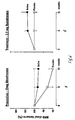
- Figure 2 shows the bones of the forearm with a region of interest ROI for use according to the invention in monitoring bisphosphonate therapy.
- the ROI is divided into two spaced sub-areas, the readings from which are summed.
- a first trapezoidal sub-area 12 toward the distal end of the radius 10 is a first trapezoidal sub-area 12 and toward the distal end of the ulna 14 is a trapezoidal second sub-area 14.
- the dimensions of these areas are shown in Figures 2 and 3.
- Sub-area 12 has sides of 14mm, 14.56mm (2), and 6mm
- whilst sub-area 14 has sides of 8mm, 11.764mm (2), and 2.4 mm. The precise dimensions given are default.
- This total trapezium area, both for radius and ulna can be increased and decreased, in such a way that all 4 lines are moved simultaneously, keeping the shape of the trapezium at all times. The same is the case when decreasing the area.
- Other dimensions could be chosen within the general constraints described below.
- the sub-areas are located in a patient's arm in positions deducible by the following procedure. On an X-ray scan of the arm, the junction or turning point between the inside of the radius and the ulna at the position marked A in Figure 4 is located.
- a 32mm line A-M is constructed horizontally in the figure in the proximal direction.
- a line X-X is constructed through M transverse to A-M 32mm proximal of A.
- a point E is constructed on line X-X such that the distance C-D between the intercept of the midline of the radius and the line X-X at C and the intercept between the inner margin of the radius and the line X-X at D is equal to the distance D-E.
- a reference line A-E is constructed.
- the trapezoid 12 is then moved distally to a position 1.2mm proximal of the end plate of the radius at F.
- the trapezoid 12 is then rotated about B1 until the line C1-D1 is bisected by the mid line of the radius at G.
- the location of the sub-area 12 may now be recorded for future use as vector coordinates based on the distance of each corner A1, B1, C1 and D1 from the point A, and the angle made with the line A-E by each line joining a respective corner to the point A, eg. the angle between A-A1 and the line A-E.
- the sub region 14 in the ulna is located by the same procedure, except that the lines and points are reflected across the line A-M, such that the equivalents of C, D and E for example are C u , D u and E u .
- an area which is designed to be as large as possible within the constraints of avoiding the cortical bone at the end plate of the radius or ulna, avoiding the cortical bone at the side edges of the bones, and in the proximal direction avoiding the cortical rich part of the bone that has been measured conventionally in the past.
- the area as defined above is of course designed to be locatable in different patients in a consistent manner and to be relocatable reliably in the same patient on different occasions.
- bone densitometers scan an area which includes but extends beyond the specific region of interest and present a visual image representing the whole scan. Data is stored for the whole scan. Either automatically or in response to selection by the operator working on the image produced a region of interest is then defined and the bone densitometry read outs are calculated from the data relating to this region only.
- the region of interest is defined having regard to the therapeutic treatment to be followed, so reflecting differences in the way in which different therapeutics affect the density of different bone types and areas.
- the bone densitometry read outs at the start of treatment and at later times as the treatment progresses will all be based on the same region of interest, so that the effect of the treatment may be followed. If later the treatment is changed, new values for the bone densitometry readouts from all the previous scans including the first scan may be calculated appropriate to that new treatment by going back to the stored data for the whole of each previous scan and reselecting a new region of interest, which will also be used in subsequent scans.
- the scanner used calculates its bone densitometry readouts from an area of bone illustrated in Figure 1.
Landscapes
- Health & Medical Sciences (AREA)
- Life Sciences & Earth Sciences (AREA)
- Medical Informatics (AREA)
- Engineering & Computer Science (AREA)
- Pathology (AREA)
- Heart & Thoracic Surgery (AREA)
- Oral & Maxillofacial Surgery (AREA)
- Biophysics (AREA)
- High Energy & Nuclear Physics (AREA)
- Dentistry (AREA)
- Nuclear Medicine, Radiotherapy & Molecular Imaging (AREA)
- Optics & Photonics (AREA)
- Orthopedic Medicine & Surgery (AREA)
- Radiology & Medical Imaging (AREA)
- Biomedical Technology (AREA)
- Physics & Mathematics (AREA)
- Molecular Biology (AREA)
- Surgery (AREA)
- Animal Behavior & Ethology (AREA)
- General Health & Medical Sciences (AREA)
- Public Health (AREA)
- Veterinary Medicine (AREA)
- Apparatus For Radiation Diagnosis (AREA)
- Prostheses (AREA)
- Magnetic Resonance Imaging Apparatus (AREA)
- Measurement Of Radiation (AREA)
- Ultra Sonic Daignosis Equipment (AREA)
Claims (11)
- Vorrichtung für die Röntgenstrahl-Knochendichtemessung des Unterarms, die umfasst: eine Röntgenstrahlquelle und einen Röntgenstrahldetektor sowie Mittel zum Speichern von Knochendichtemessdaten, die aus der Detektion von Röntgenstrahlen durch den Detektor nach deren Durchgang durch den Unterarm eines Patienten abgeleitet werden, und Mittel, um diese Daten zu verarbeiten, um eine Knochendichtemessungsangabe aus Daten zu erhalten, die mit einem Knochenbereich (12, 14) in Beziehung stehen, der in der Vorrichtung als durch den Radius (10) und/oder die Ulna (11) definiert berechnet wird, um so eine distale Grenze (A1) zu erhalten, die distal zu dem Drehpunkt (A) zwischen dem Radius und der Ulna, jedoch proximal zu dem dichten (A1-D1, B1-C1) kortikalen Bereich der Stirnplatte des Knochens (E) liegt, wobei Seitenkanten in dem Knochen innerhalb der dichten kortikalen Grenzen des Knochens liegen und sich in proximaler Richtung über den Drehpunkt hinaus erstrecken, ohne jedoch in Bereiche einzudringen, in denen ein mehr kortikaler als trabekulärer Knochen vorhanden ist.
- Vorrichtung nach Anspruch 1, bei der der Knochenbereich trapezförmig ist, wobei sich die längere der zwei parallelen Seiten distal zu der kürzeren befindet.
- Vorrichtung nach Anspruch 1, bei der die Länge des Bereichs in distalproximaler Richtung gleich der 0,9- bis 1,1-fachen maximalen Breite des Bereichs für den Radius oder gleich der 1,2- bis 1,5-fachen maximalen Breite für die Ulna ist.
- Vorrichtung nach einem der Ansprüche 1 bis 3, bei der der Bereich unter einem Winkel im Bereich von 10 bis 15° auf jeder Seite konisch zuläuft.
- Vorrichtung nach Anspruch 2, bei der das Trapezoid definiert ist durch: Anordnen des Drehpunkts (A) zwischen dem Radius und der Ulna, Konstruieren einer ersten Linie (A-M) von dem Drehpunkt parallel zur Achse des Arms, Definieren einer zweiten Linie (X-X) 32 mm proximal zu dem Drehpunkt und senkrecht zu der ersten Linie, Definieren eines Punkts (E) auf der zweiten Linie, derart, dass der Abstand (C-D) zwischen dem Schnittpunkt (C) der Mittellinie des Radius und der zweiten Linie und dem Schnittpunkt (D) der inneren Grenze des Radius und der zweiten Linie gleich dem Abstand (D-E) von dem Punkt (E) zu dem Schnittpunkt (D) zwischen der inneren Grenze des Radius und der zweiten Linie ist, Konstruieren einer Bezugslinie (A-E) von dem Drehpunkt zu dem definierten Punkt, Definieren eines Trapezoids (12), dessen längere parallele Seite (A1-B1) auf der Linie zwischen dem Drehpunkt (A) und dem Punkt (T) auf der Außenkante des Radius oder der Ulna und auf der gleichen distal-proximalen Höhe wie der Drehpunkt liegt, so dass der Abstand zwischen dem Punkt (T) auf der Außenkante des Radius oder der Ulna und dem benachbarten Vertex (A1) des Trapezoids gleich dem Abstand zwischen dem Vertex (B1) am anderen Ende der längeren parallelen Seite und dem Drehpunkt (A) ist, Bewegen des Trapezoids zu einer Position, die sich in einem Abstand von 1,2 mm von der Stirnplatte des Radius bzw. der Ulna befindet, und Drehen des Trapezoids um den inneren Vertex (B1) einschließlich der längeren parallelen Seite hiervon, bis die kürzere parallele Seite (C1-D1) hiervon durch die Mittellinie des Radius bzw. der Ulna halbiert wird.
- Vorrichtung nach Anspruch 1 oder Anspruch 5, bei der die Größe des interessierenden Trapezoid-Bereichs gleich 14 × 14,6 × 6 × 14,6 mm für den Radius oder 8 × 11,4 x 2,4 × 11,8 für die Ulna ist.
- Vorrichtung nach Anspruch 1, die ferner umfasst:Mittel zum Speichern von Informationen, die auf mehrere Knochenerkrankungsbehandlungen bezogen sind, undMittel, um mehrere Körperbereiche zu definieren, die jenen Knochenbereich (12, 14) als einen solchen Körperbereich enthalten, um in Bezug darauf Informationen aus gespeicherten Knochendichteinformationen auszuwählen oder um daraus die Knochendichteinformationen zu erhalten, um sie zu verarbeiten, um eine Knochendichtemessungsangabe, die mit dem definierten Körperbereich in Beziehung steht, abzuleiten,wobei die Körperbereich-Definitionsmittel auf die von einer Bedienungsperson vorgenommene Wahl einer Behandlung aus Behandlungen, für die Informationen gespeichert sind, ansprechen.
- Vorrichtung nach Anspruch 7, bei der die Behandlungen auf unterschiedliche Medikamente bezogen sind.
- Vorrichtung nach Anspruch 7 oder 8, bei der die Informationen, die auf die Behandlungen bezogen sind, einen entsprechenden Körperbereich identifizieren, der in den Körperbereich-Definitionsmitteln in Bezug auf jeden Behandlungsvorgang, für den Informationen gespeichert sind, zu definieren ist.
- Verfahren zum Verarbeiten von Knochendichtemessungsdaten, die durch eine Röntgenstrahl-Knochendichtemessung des Unterarms erhalten werden, bei dem eine Knochendichtemessungsangabe erhalten wird aus Daten, die auf einen Knochenbereich (12, 14) bezogen sind, der im Radius (10) und/oder der Ulna (11) definiert ist, um so eine distale Grenze (A1) zu erhalten, die distal von dem Drehpunkt (A) zwischen dem Radius und der Ulna, jedoch proximal zu dem dichten (A1-D1, B1-C1) kortikalen Bereich der Stirnplatte des Knochens (A) liegt, wobei Seitenkanten in dem Knochen innerhalb der dichten kortikalen Bereiche des Knochens liegen und sich in proximaler Richtung über den Drehpunkt hinaus erstrecken, ohne jedoch in Bereiche einzudringen, in denen ein eher kortikaler als trabekulärer Knochen vorhanden ist.
- Verfahren nach Anspruch 10, bei dem der Knochenbereich von der Art ist, die ferner in einem der Ansprüche 2 bis 6 definiert ist.
Applications Claiming Priority (3)
| Application Number | Priority Date | Filing Date | Title |
|---|---|---|---|
| GB9609814 | 1996-05-10 | ||
| GBGB9609814.0A GB9609814D0 (en) | 1996-05-10 | 1996-05-10 | Bone densitometry apparatus |
| PCT/EP1997/002369 WO1997042874A1 (en) | 1996-05-10 | 1997-05-09 | Bone densitometry apparatus |
Publications (2)
| Publication Number | Publication Date |
|---|---|
| EP0902646A1 EP0902646A1 (de) | 1999-03-24 |
| EP0902646B1 true EP0902646B1 (de) | 2006-08-30 |
Family
ID=10793508
Family Applications (1)
| Application Number | Title | Priority Date | Filing Date |
|---|---|---|---|
| EP97923857A Expired - Lifetime EP0902646B1 (de) | 1996-05-10 | 1997-05-09 | Gerät zur dichtemessung von knochen |
Country Status (9)
| Country | Link |
|---|---|
| US (1) | US6058157A (de) |
| EP (1) | EP0902646B1 (de) |
| JP (1) | JP2000510723A (de) |
| AT (1) | ATE337728T1 (de) |
| AU (1) | AU2952897A (de) |
| CA (1) | CA2254938A1 (de) |
| DE (1) | DE69736595D1 (de) |
| GB (1) | GB9609814D0 (de) |
| WO (1) | WO1997042874A1 (de) |
Families Citing this family (9)
| Publication number | Priority date | Publication date | Assignee | Title |
|---|---|---|---|---|
| US6510197B1 (en) | 2000-01-11 | 2003-01-21 | Alara, Inc. | Method and apparatus for osteoporosis screening |
| US8085898B2 (en) * | 2009-05-08 | 2011-12-27 | Osteometer Meditech, Inc. | Apparatus for bone density assessment and monitoring |
| US20100135458A1 (en) * | 2003-07-18 | 2010-06-03 | Neeraj Agrawal | X-Ray Apparatus for Bone Density Assessment and Monitoring |
| US8343923B2 (en) * | 2007-11-09 | 2013-01-01 | Washington University | Use of notch signaling regulators for modulating osteogenesis |
| EP2214013A1 (de) | 2009-01-28 | 2010-08-04 | Universitätsklinikum Freiburg | Verfahren zur Behandlung von Knochenerkrankungen |
| USD663601S1 (en) * | 2010-05-17 | 2012-07-17 | Mel Colangelo | Hammer |
| US9044186B2 (en) | 2012-06-25 | 2015-06-02 | George W. Ma | Portable dual-energy radiographic X-ray perihpheral bone density and imaging systems and methods |
| JP5882277B2 (ja) * | 2013-09-26 | 2016-03-09 | 日立アロカメディカル株式会社 | 骨密度測定装置 |
| JP6563671B2 (ja) * | 2015-04-08 | 2019-08-21 | 株式会社日立製作所 | 骨塩量測定装置 |
Family Cites Families (7)
| Publication number | Priority date | Publication date | Assignee | Title |
|---|---|---|---|---|
| EP0411155B1 (de) * | 1989-02-23 | 1997-05-02 | Teijin Limited | Verfahren zum messen einer knochenform, vorrichtung dafür sowie system zur knochenevaluation |
| US5138553A (en) * | 1989-03-10 | 1992-08-11 | Expert Image Systems, Inc. | Method and apparatus for bone mineral measurement using a measurement region defined at a selected distance from a styloid bone tip |
| US5228445A (en) * | 1990-06-18 | 1993-07-20 | Board Of Regents, The University Of Texas System | Demonstration by in vivo measurement of reflection ultrasound analysis of improved bone quality following slow-release fluoride treatment in osteoporosis patients |
| DE69422130T2 (de) * | 1993-04-23 | 2000-07-20 | Teijin Ltd., Osaka | Osteometrie und osteometrische vorrichtung |
| US5748705A (en) * | 1993-11-22 | 1998-05-05 | Hologic Inc. | X-ray bone densitometry |
| US5641747A (en) * | 1994-07-25 | 1997-06-24 | Temple University-Of The Commonwealth System Of Higher Education | Treatment of osteopetrotic diseases |
| US5594775A (en) * | 1995-04-19 | 1997-01-14 | Wright State University | Method and apparatus for the evaluation of cortical bone by computer tomography |
-
1996
- 1996-05-10 GB GBGB9609814.0A patent/GB9609814D0/en active Pending
-
1997
- 1997-05-09 AU AU29528/97A patent/AU2952897A/en not_active Abandoned
- 1997-05-09 CA CA002254938A patent/CA2254938A1/en not_active Abandoned
- 1997-05-09 WO PCT/EP1997/002369 patent/WO1997042874A1/en not_active Ceased
- 1997-05-09 DE DE69736595T patent/DE69736595D1/de not_active Expired - Lifetime
- 1997-05-09 AT AT97923857T patent/ATE337728T1/de not_active IP Right Cessation
- 1997-05-09 EP EP97923857A patent/EP0902646B1/de not_active Expired - Lifetime
- 1997-05-09 JP JP09540493A patent/JP2000510723A/ja active Pending
-
1998
- 1998-11-09 US US09/188,333 patent/US6058157A/en not_active Expired - Lifetime
Also Published As
| Publication number | Publication date |
|---|---|
| CA2254938A1 (en) | 1997-11-20 |
| JP2000510723A (ja) | 2000-08-22 |
| EP0902646A1 (de) | 1999-03-24 |
| WO1997042874A1 (en) | 1997-11-20 |
| DE69736595D1 (de) | 2006-10-12 |
| US6058157A (en) | 2000-05-02 |
| ATE337728T1 (de) | 2006-09-15 |
| AU2952897A (en) | 1997-12-05 |
| GB9609814D0 (en) | 1996-07-17 |
Similar Documents
| Publication | Publication Date | Title |
|---|---|---|
| US5291537A (en) | Device and method for automated determination and analysis of bone density and vertebral morphology | |
| Laib et al. | Ridge number density: a new parameter for in vivo bone structure analysis | |
| US5577089A (en) | Device and method for analysis of bone morphology | |
| ROSENTHAL et al. | Quantitative computed tomography for spinal density measurement factors affecting precision | |
| US5509042A (en) | Automated determination and analysis of bone morphology | |
| EP0448627B1 (de) | Quantitatives rechnergestütztes tomographiesystem | |
| O'Leary et al. | Measurement variability of carotid atherosclerosis: real-time (B-mode) ultrasonography and angiography. | |
| Sharp et al. | Computer‐based methods for measuring joint space and estimating erosion volume in the finger and wrist joints of patients with rheumatoid arthritis | |
| US6160866A (en) | Apparatus for bilateral femur measurement | |
| Helms et al. | Detection of bone-marrow metastases using quantitative computed tomography. | |
| JP2003514641A (ja) | 将来の骨折危険性を決定する装置及び方法 | |
| EP0902646B1 (de) | Gerät zur dichtemessung von knochen | |
| Kalender et al. | Bone mineral measurement: automated determination of midvertebral CT section. | |
| US5860929A (en) | Fractional moving blood volume estimation with power doppler ultrasound | |
| US5745544A (en) | Bone densitometer with film cassette | |
| Jefferson et al. | Scoliosis surgery and its effect on back shape | |
| WO1994006351A1 (en) | Automated determination and analysis of bone morphology | |
| EP1684233A1 (de) | Verfahren und Vorrichtung zur Erstellung eines Nierenbildes | |
| EP0793446A1 (de) | Dichtemesser für knochen mit filmkassette | |
| Burston et al. | Determination of a standard site for the measurement of bone mineral density of the human calcaneus | |
| Theodorou et al. | Quantitative computed tomography of spine: comparison of three-dimensional and two-dimensional imaging approaches in clinical practice | |
| Corcoran et al. | Calculation of cross-sectional geometry of bone from CT images with application in postmenopausal women | |
| Orhan et al. | Comparison of accuracy of three-dimensional spiral computed tomography, standard radiography, and direct measurements in evaluating facial fracture healing in a rat model | |
| RU2808009C1 (ru) | Способ топографии участков нижней челюсти для измерения оптической плотности кортикального и трабекулярного вещества на сканах позитронно-эмиссионной томографии (ПЭТ-КТ сканах) | |
| Greenough et al. | Lumbar spinal canal morphometry from computed tomography scans: reproducibility, results and clinical implications |
Legal Events
| Date | Code | Title | Description |
|---|---|---|---|
| PUAI | Public reference made under article 153(3) epc to a published international application that has entered the european phase |
Free format text: ORIGINAL CODE: 0009012 |
|
| 17P | Request for examination filed |
Effective date: 19981124 |
|
| AK | Designated contracting states |
Kind code of ref document: A1 Designated state(s): AT BE CH DE DK ES FI FR GB GR IE IT LI LU MC NL PT SE |
|
| 17Q | First examination report despatched |
Effective date: 20010606 |
|
| GRAP | Despatch of communication of intention to grant a patent |
Free format text: ORIGINAL CODE: EPIDOSNIGR1 |
|
| GRAS | Grant fee paid |
Free format text: ORIGINAL CODE: EPIDOSNIGR3 |
|
| GRAA | (expected) grant |
Free format text: ORIGINAL CODE: 0009210 |
|
| AK | Designated contracting states |
Kind code of ref document: B1 Designated state(s): AT BE CH DE DK ES FI FR GB GR IE IT LI LU MC NL PT SE |
|
| PG25 | Lapsed in a contracting state [announced via postgrant information from national office to epo] |
Ref country code: NL Free format text: LAPSE BECAUSE OF FAILURE TO SUBMIT A TRANSLATION OF THE DESCRIPTION OR TO PAY THE FEE WITHIN THE PRESCRIBED TIME-LIMIT Effective date: 20060830 Ref country code: LI Free format text: LAPSE BECAUSE OF FAILURE TO SUBMIT A TRANSLATION OF THE DESCRIPTION OR TO PAY THE FEE WITHIN THE PRESCRIBED TIME-LIMIT Effective date: 20060830 Ref country code: IT Free format text: LAPSE BECAUSE OF FAILURE TO SUBMIT A TRANSLATION OF THE DESCRIPTION OR TO PAY THE FEE WITHIN THE PRESCRIBED TIME-LIMIT;WARNING: LAPSES OF ITALIAN PATENTS WITH EFFECTIVE DATE BEFORE 2007 MAY HAVE OCCURRED AT ANY TIME BEFORE 2007. THE CORRECT EFFECTIVE DATE MAY BE DIFFERENT FROM THE ONE RECORDED. Effective date: 20060830 Ref country code: FI Free format text: LAPSE BECAUSE OF FAILURE TO SUBMIT A TRANSLATION OF THE DESCRIPTION OR TO PAY THE FEE WITHIN THE PRESCRIBED TIME-LIMIT Effective date: 20060830 Ref country code: CH Free format text: LAPSE BECAUSE OF FAILURE TO SUBMIT A TRANSLATION OF THE DESCRIPTION OR TO PAY THE FEE WITHIN THE PRESCRIBED TIME-LIMIT Effective date: 20060830 Ref country code: BE Free format text: LAPSE BECAUSE OF FAILURE TO SUBMIT A TRANSLATION OF THE DESCRIPTION OR TO PAY THE FEE WITHIN THE PRESCRIBED TIME-LIMIT Effective date: 20060830 Ref country code: AT Free format text: LAPSE BECAUSE OF FAILURE TO SUBMIT A TRANSLATION OF THE DESCRIPTION OR TO PAY THE FEE WITHIN THE PRESCRIBED TIME-LIMIT Effective date: 20060830 |
|
| REG | Reference to a national code |
Ref country code: CH Ref legal event code: EP |
|
| REG | Reference to a national code |
Ref country code: IE Ref legal event code: FG4D |
|
| REF | Corresponds to: |
Ref document number: 69736595 Country of ref document: DE Date of ref document: 20061012 Kind code of ref document: P |
|
| PG25 | Lapsed in a contracting state [announced via postgrant information from national office to epo] |
Ref country code: SE Free format text: LAPSE BECAUSE OF FAILURE TO SUBMIT A TRANSLATION OF THE DESCRIPTION OR TO PAY THE FEE WITHIN THE PRESCRIBED TIME-LIMIT Effective date: 20061130 Ref country code: DK Free format text: LAPSE BECAUSE OF FAILURE TO SUBMIT A TRANSLATION OF THE DESCRIPTION OR TO PAY THE FEE WITHIN THE PRESCRIBED TIME-LIMIT Effective date: 20061130 |
|
| PG25 | Lapsed in a contracting state [announced via postgrant information from national office to epo] |
Ref country code: DE Free format text: LAPSE BECAUSE OF FAILURE TO SUBMIT A TRANSLATION OF THE DESCRIPTION OR TO PAY THE FEE WITHIN THE PRESCRIBED TIME-LIMIT Effective date: 20061201 |
|
| PG25 | Lapsed in a contracting state [announced via postgrant information from national office to epo] |
Ref country code: ES Free format text: LAPSE BECAUSE OF FAILURE TO SUBMIT A TRANSLATION OF THE DESCRIPTION OR TO PAY THE FEE WITHIN THE PRESCRIBED TIME-LIMIT Effective date: 20061211 |
|
| PG25 | Lapsed in a contracting state [announced via postgrant information from national office to epo] |
Ref country code: PT Free format text: LAPSE BECAUSE OF FAILURE TO SUBMIT A TRANSLATION OF THE DESCRIPTION OR TO PAY THE FEE WITHIN THE PRESCRIBED TIME-LIMIT Effective date: 20070206 |
|
| REG | Reference to a national code |
Ref country code: CH Ref legal event code: PL |
|
| NLV1 | Nl: lapsed or annulled due to failure to fulfill the requirements of art. 29p and 29m of the patents act | ||
| EN | Fr: translation not filed | ||
| PLBE | No opposition filed within time limit |
Free format text: ORIGINAL CODE: 0009261 |
|
| STAA | Information on the status of an ep patent application or granted ep patent |
Free format text: STATUS: NO OPPOSITION FILED WITHIN TIME LIMIT |
|
| 26N | No opposition filed |
Effective date: 20070531 |
|
| GBPC | Gb: european patent ceased through non-payment of renewal fee |
Effective date: 20070509 |
|
| PG25 | Lapsed in a contracting state [announced via postgrant information from national office to epo] |
Ref country code: MC Free format text: LAPSE BECAUSE OF NON-PAYMENT OF DUE FEES Effective date: 20070531 |
|
| PG25 | Lapsed in a contracting state [announced via postgrant information from national office to epo] |
Ref country code: GR Free format text: LAPSE BECAUSE OF FAILURE TO SUBMIT A TRANSLATION OF THE DESCRIPTION OR TO PAY THE FEE WITHIN THE PRESCRIBED TIME-LIMIT Effective date: 20061201 Ref country code: FR Free format text: LAPSE BECAUSE OF FAILURE TO SUBMIT A TRANSLATION OF THE DESCRIPTION OR TO PAY THE FEE WITHIN THE PRESCRIBED TIME-LIMIT Effective date: 20070511 |
|
| PG25 | Lapsed in a contracting state [announced via postgrant information from national office to epo] |
Ref country code: IE Free format text: LAPSE BECAUSE OF NON-PAYMENT OF DUE FEES Effective date: 20070509 Ref country code: GB Free format text: LAPSE BECAUSE OF NON-PAYMENT OF DUE FEES Effective date: 20070509 |
|
| PG25 | Lapsed in a contracting state [announced via postgrant information from national office to epo] |
Ref country code: FR Free format text: LAPSE BECAUSE OF FAILURE TO SUBMIT A TRANSLATION OF THE DESCRIPTION OR TO PAY THE FEE WITHIN THE PRESCRIBED TIME-LIMIT Effective date: 20060830 |
|
| PG25 | Lapsed in a contracting state [announced via postgrant information from national office to epo] |
Ref country code: LU Free format text: LAPSE BECAUSE OF NON-PAYMENT OF DUE FEES Effective date: 20070509 |