EP0902301B1 - Opto-elektronische Beobachtungsvorrichtung mit verbesserter Detektion von Laserschüssen - Google Patents
Opto-elektronische Beobachtungsvorrichtung mit verbesserter Detektion von Laserschüssen Download PDFInfo
- Publication number
- EP0902301B1 EP0902301B1 EP19980402183 EP98402183A EP0902301B1 EP 0902301 B1 EP0902301 B1 EP 0902301B1 EP 19980402183 EP19980402183 EP 19980402183 EP 98402183 A EP98402183 A EP 98402183A EP 0902301 B1 EP0902301 B1 EP 0902301B1
- Authority
- EP
- European Patent Office
- Prior art keywords
- video
- observation device
- images
- laser
- difference
- Prior art date
- Legal status (The legal status is an assumption and is not a legal conclusion. Google has not performed a legal analysis and makes no representation as to the accuracy of the status listed.)
- Expired - Lifetime
Links
- 230000005693 optoelectronics Effects 0.000 title claims description 13
- 230000015654 memory Effects 0.000 claims description 15
- 230000003287 optical effect Effects 0.000 claims description 11
- 238000012163 sequencing technique Methods 0.000 description 4
- 230000001681 protective effect Effects 0.000 description 3
- 238000012550 audit Methods 0.000 description 2
- 238000010586 diagram Methods 0.000 description 1
- 230000004044 response Effects 0.000 description 1
- 230000001360 synchronised effect Effects 0.000 description 1
Images
Classifications
-
- G—PHYSICS
- G02—OPTICS
- G02B—OPTICAL ELEMENTS, SYSTEMS OR APPARATUS
- G02B23/00—Telescopes, e.g. binoculars; Periscopes; Instruments for viewing the inside of hollow bodies; Viewfinders; Optical aiming or sighting devices
- G02B23/12—Telescopes, e.g. binoculars; Periscopes; Instruments for viewing the inside of hollow bodies; Viewfinders; Optical aiming or sighting devices with means for image conversion or intensification
-
- G—PHYSICS
- G01—MEASURING; TESTING
- G01S—RADIO DIRECTION-FINDING; RADIO NAVIGATION; DETERMINING DISTANCE OR VELOCITY BY USE OF RADIO WAVES; LOCATING OR PRESENCE-DETECTING BY USE OF THE REFLECTION OR RERADIATION OF RADIO WAVES; ANALOGOUS ARRANGEMENTS USING OTHER WAVES
- G01S7/00—Details of systems according to groups G01S13/00, G01S15/00, G01S17/00
- G01S7/48—Details of systems according to groups G01S13/00, G01S15/00, G01S17/00 of systems according to group G01S17/00
- G01S7/483—Details of pulse systems
Definitions
- the present invention relates to devices observation systems with optical system for observation a field, an associated optoelectronic detector audit optical system to form the electronic image of said field and of video means receiving said image electronic and displaying the corresponding video image of said field.
- US-A-5,153,425 describes a protective device against such laser attacks, thanks to which the laser beams reaching such an observation device are automatically reflected and absorbed without power damage or destroy it, without even the observer watching the video image of the field knowledge.
- the object of the present invention is to improve an observation device of the type mentioned above and protected by the aforementioned protection device, so to alert said observer to the fact that a beam laser has reached said observation device.
- the two successive electronic images are identical, of so their difference is zero and nothing is superimposed video images appearing on said video means.
- the protective device reflects and absorbs the corresponding laser beam, so that, on the sensitive optoelectronic element of said detector, the pixel or pixels corresponding to the location where said laser beam hit are obscured.
- the difference between said successive images is no longer null, but on the contrary formed by said one or more obscured pixels.
- said video control means accentuate the obscured pixel (s) to make them appear unambiguously on said display means video.
- said pixels video control means can, on said means display, magnify those obscured pixels, or display a particular mark centered on said pixels, such as a circle, a crosshair, etc.
- said video control means may render fixes the image displayed on said display means video, when said difference is representative of a laser shot.
- Said video control means can also order additional memory means for store, in the event that a laser shot reaches said device observation, the image resulting from the overlay of said difference and one of said video images displayed corresponding.
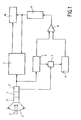
- Figure 1 shows the block diagram of a device advanced optoelectronic observation to the present invention.
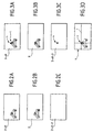
- Figures 2A, 2B and 2C illustrate the operation of the optoelectronic observation device of the Figure 1, when no laser shot reaches said device.
- Figures 3A, 3B, 3C and 3D illustrate the operation of the optoelectronic observation device of Figure 1, when a laser shot reaches said device.
- the observation device illustrated schematically in Figure 1, includes an optical system 1 observing an optical field C from which it receives beams luminous F.
- the optical system 1 is associated with a detector optoelectronics 2, which forms an electronic image of said field, and is protected against laser fire by a protection device 3 .
- These measures protection 3 lets all the light rays through, except for the laser beams it reflects and absorbs.
- the electronic image generated by the detector optoelectronics 2 is transmitted to video means 4 which display the corresponding video image of field C observed by the optical system 1.
- the observation device of FIG. 1 comprises in addition two electronic memories 5 and 6 and a device 7 image transfer, synchronized with sequencing said images in the optoelectronic detector 2.
- the input of the electronic memory 5 is connected at the output of the optoelectronic detector 2, in parallel with video resources 4.
- the electronic image It appearing at the output of the optoelectronic detector 2 is simultaneously displayed on the video means 4 and recorded in memory 5.
- the previous electronic image It is transferred into memory 6 by the device transfer 7, while the current electronic image It + dt is simultaneously displayed on the means. video 4 and stored in memory 5.
- the electronic image previous It + dt is transferred to memory 6 by the transfer device 7, while the electronic image It + 2dt is simultaneously displayed on the video means and stored in memory 5, etc ...
- memory 5 contains the current image of field C
- the memory 6 contains the previous image of said field.
- the outputs of memories 5 and 6 are respectively. connected to two inputs of a subtractor 8, the output of which is connected to the video means 4 by superposition means 9.
- the observer looking at said display means video 4 is therefore alerted to the laser shot aimed at the observation device and it can determine the origin of this laser shot.
- the device according to the present invention can have an additional memory 10 in which is stored, under the control of said video control means 9, the image of the field C with the superimposed r reticle, as shown in Figure 3D.
Landscapes
- Physics & Mathematics (AREA)
- Engineering & Computer Science (AREA)
- General Physics & Mathematics (AREA)
- Computer Networks & Wireless Communication (AREA)
- Radar, Positioning & Navigation (AREA)
- Remote Sensing (AREA)
- Astronomy & Astrophysics (AREA)
- Optics & Photonics (AREA)
- Photometry And Measurement Of Optical Pulse Characteristics (AREA)
- Microscoopes, Condenser (AREA)
- Telescopes (AREA)
- Closed-Circuit Television Systems (AREA)
Claims (6)
- Beobachtungsvorrichtung, die folgendes umfasst:dadurch gekennzeichnet, dass sie weiterhin folgendes umfasst:ein optisches System (1) zur Beobachtung eines Felds (C), in dem es zu Laserschüssen kommen kann;einen dem genannten optischen System zur Bildung einer Folge von elektronischen Bildem des genannten Felds zugeordneten opto-elektronischen Detektor (2);Videoanzeigemittel (4), die die genannten elektronischen Bilder empfangen und die entsprechenden Videobilder des genannten Felds anzeigen; undeine Schutzvorrichtung (3), die die Laserstrahtenbündel, die auf die genannte Beobachtungsvorrichtung treffen, reflektieren und absorbieren,Speichermittel (5, 6), die mindestens zwei aufeinanderfolgende elektronische Bilder des genannten Felds ( C) speichern können;Subtraktionsmittel (8), die es ermöglichen, eines der genannten elektronischen Bilder zum Erhalt der Differenz von beiden vom anderen zu subtrahieren; undVideosteuermittel (9), die es ermöglichen, die genannte Differenz über die genannten, von den genannten Videoanzeigemitteln (4) angezeigten Bilder zumindest dann zu legen, wenn ein Laserschuss die genannte Beobachtungsvorrichtung getroffen hat.
- Beobachtungsvorrichtung gemäß Anspruch 1,
dadurch gekennzeichnet, dass die genannte Differenz, wenn ein Laserschuss die genannte Beobachtungsvorrichtung getroffen hat, von mindestens einem abgedunkelten Bildpixel (n) gebildet wird und dass die genannten videosteuermittel (9) das genannte abgedunkelte Pixel verstärken, damit es deutlich auf den genannten Videoanzeigemitteln (4) erscheint. - Beobachtungsvorrichtung gemäß Anspruch 2,
dadurch gekennzeichnet, dass die genannten Videosteuermittel (9) zur Verstärkung des genannten abgedunkelten Pixels (n) auf den genannten Videoanzeigemitteln (4) eine Marke (r) anzeigen, die auf den genannten abgedunkelten Pixel zentriert ist. - Beobachtungsvorrichtung gemäß Anspruch 3,
dadurch gekennzeichnet, dass die genannte Marke ein Strichkreuz (r) ist. - Beobachtungsvorrichtung gemäß einem der Ansprüche 1 bis 4,
dadurch gekennzeichnet, dass die genannten Videosteuermittel (9) das auf den genannten Videoanzeigemitteln angezeigte Bild fixieren, wenn die genannte Differenz repräsentativ für einen Laserschuss ist. - Beobachtungsvorrichtung gemäß einem der Ansprüche 1 bis 5,
dadurch gekennzeichnet, dass sie zusätzliche Speichermittel (10) umfasst, um für den Fall, dass ein Laserschuss die Beobachtungsvorrichtung getroffen hat, das sich aus dem Übereinandedegen der genannten Differenz und eines der genannten entsprechenden angezeigten Videobilder ergebende Bild zu speichem.
Applications Claiming Priority (2)
| Application Number | Priority Date | Filing Date | Title |
|---|---|---|---|
| FR9711157 | 1997-09-09 | ||
| FR9711157A FR2768235B1 (fr) | 1997-09-09 | 1997-09-09 | Dispositif d'observation optoelectronique perfectionne pour detecter les tirs laser |
Publications (2)
| Publication Number | Publication Date |
|---|---|
| EP0902301A1 EP0902301A1 (de) | 1999-03-17 |
| EP0902301B1 true EP0902301B1 (de) | 2003-07-09 |
Family
ID=9510870
Family Applications (1)
| Application Number | Title | Priority Date | Filing Date |
|---|---|---|---|
| EP19980402183 Expired - Lifetime EP0902301B1 (de) | 1997-09-09 | 1998-09-03 | Opto-elektronische Beobachtungsvorrichtung mit verbesserter Detektion von Laserschüssen |
Country Status (4)
| Country | Link |
|---|---|
| EP (1) | EP0902301B1 (de) |
| DE (1) | DE69816206T2 (de) |
| ES (1) | ES2197435T3 (de) |
| FR (1) | FR2768235B1 (de) |
Families Citing this family (1)
| Publication number | Priority date | Publication date | Assignee | Title |
|---|---|---|---|---|
| DE102010010030B4 (de) * | 2010-03-03 | 2013-02-21 | Diehl Bgt Defence Gmbh & Co. Kg | Vorrichtung zum Darstellen einer Umgebung |
Family Cites Families (4)
| Publication number | Priority date | Publication date | Assignee | Title |
|---|---|---|---|---|
| JPS58220588A (ja) * | 1982-06-17 | 1983-12-22 | Toshiba Corp | 映像信号処理装置 |
| JPS63232579A (ja) * | 1987-03-19 | 1988-09-28 | Mitsubishi Electric Corp | 固体撮像装置 |
| US5153425A (en) * | 1990-12-24 | 1992-10-06 | United Technologies Corporation | Broadband optical limiter with sacrificial mirror to prevent irradiation of a sensor system by high intensity laser radiation |
| KR0166729B1 (ko) * | 1993-11-24 | 1999-03-20 | 김광호 | 공간정보를 이용한 움직임 검출회로 및 그 방법 |
-
1997
- 1997-09-09 FR FR9711157A patent/FR2768235B1/fr not_active Expired - Lifetime
-
1998
- 1998-09-03 ES ES98402183T patent/ES2197435T3/es not_active Expired - Lifetime
- 1998-09-03 EP EP19980402183 patent/EP0902301B1/de not_active Expired - Lifetime
- 1998-09-03 DE DE69816206T patent/DE69816206T2/de not_active Expired - Lifetime
Also Published As
| Publication number | Publication date |
|---|---|
| ES2197435T3 (es) | 2004-01-01 |
| FR2768235A1 (fr) | 1999-03-12 |
| DE69816206D1 (de) | 2003-08-14 |
| FR2768235B1 (fr) | 2000-02-04 |
| EP0902301A1 (de) | 1999-03-17 |
| DE69816206T2 (de) | 2004-07-29 |
Similar Documents
| Publication | Publication Date | Title |
|---|---|---|
| CA2027286C (fr) | Dispositif de localisation en temps reel de sources de rayonnement | |
| US11927529B2 (en) | Gas detection system and method | |
| US6803577B2 (en) | Quantitative imaging of gas emissions utilizing optical techniques | |
| FR2973344A1 (fr) | Aeronef pourvu d'un systeme de surveillance | |
| EP2689403A1 (de) | Überwachungssystem | |
| WO2012007692A1 (fr) | Procédé et dispositif d'imagerie bi-spectral multifonctions | |
| FR2888333A1 (fr) | "dispositif de detection et de localisation de sources de rayonnement laser" | |
| EP0902301B1 (de) | Opto-elektronische Beobachtungsvorrichtung mit verbesserter Detektion von Laserschüssen | |
| CA2300577C (fr) | Dispositif d'emission d'images video numeriques | |
| EP1072858A1 (de) | Verfahren und Vorrichtung zur Lenkung eines Flugkörpers nach einem Ziel mittels Laserabtasten | |
| EP0452188B1 (de) | Abbildungs- und Überwachungsvorrichtung mit Matrixsensor | |
| FR3066834B1 (fr) | Procede d'assistance a l'installation d'au moins un occulteur reel pour un detecteur de presence et dispositif associe | |
| EP0187687B1 (de) | Optisch-mechanische Abtasteinheit mit festem Feld zur Entfernungsmessung | |
| Storm et al. | Trip wire detection using polarimetric IR | |
| EP2194353B1 (de) | Verfahren und System zur Erkennung von unkonventionellen Spreng- oder Brandvorrichtungen oder dergleichen | |
| FR3117219A1 (fr) | Procédé d’acquisition d’une séquence de parties d’images et système d’acquisition associé | |
| WO1999044178A1 (fr) | Dispositif de surveillance d'une enceinte, notamment de la soute d'un avion | |
| FR2942062A1 (fr) | Systemes et procedes de detection d'objets | |
| EP0540395B1 (de) | Passives Gerät zum Feststellen von Artillerieabfeuerns oder desgleichen | |
| Kastek et al. | Multisensor systems for security of critical infrastructures: concept, data fusion, and experimental results | |
| FR3138215A1 (fr) | Procédé et système de surveillance spaciale infrarouge de jour | |
| FR2909777A1 (fr) | Systeme optronique de veille passive. | |
| FR2741722A1 (fr) | Procede et dispositif d'identification active d'une cible de nuit | |
| EP3797510A1 (de) | Panoramabeobachtungssystem für plattform | |
| Henshaw et al. | Laser-speckle data collection experiments |
Legal Events
| Date | Code | Title | Description |
|---|---|---|---|
| PUAI | Public reference made under article 153(3) epc to a published international application that has entered the european phase |
Free format text: ORIGINAL CODE: 0009012 |
|
| AK | Designated contracting states |
Kind code of ref document: A1 Designated state(s): BE CH DE ES GB IT LI NL SE |
|
| AX | Request for extension of the european patent |
Free format text: AL;LT;LV;MK;RO;SI |
|
| 17P | Request for examination filed |
Effective date: 19990330 |
|
| AKX | Designation fees paid |
Free format text: BE CH DE ES GB IT LI NL SE |
|
| RAP1 | Party data changed (applicant data changed or rights of an application transferred) |
Owner name: AEROSPATIALE MATRA |
|
| GRAH | Despatch of communication of intention to grant a patent |
Free format text: ORIGINAL CODE: EPIDOS IGRA |
|
| GRAH | Despatch of communication of intention to grant a patent |
Free format text: ORIGINAL CODE: EPIDOS IGRA |
|
| GRAA | (expected) grant |
Free format text: ORIGINAL CODE: 0009210 |
|
| AK | Designated contracting states |
Designated state(s): BE CH DE ES GB IT LI NL SE |
|
| REG | Reference to a national code |
Ref country code: GB Ref legal event code: FG4D Free format text: NOT ENGLISH |
|
| REG | Reference to a national code |
Ref country code: CH Ref legal event code: EP |
|
| GBT | Gb: translation of ep patent filed (gb section 77(6)(a)/1977) | ||
| REG | Reference to a national code |
Ref country code: CH Ref legal event code: NV Representative=s name: CRONIN INTELLECTUAL PROPERTY |
|
| REF | Corresponds to: |
Ref document number: 69816206 Country of ref document: DE Date of ref document: 20030814 Kind code of ref document: P |
|
| REG | Reference to a national code |
Ref country code: SE Ref legal event code: TRGR |
|
| REG | Reference to a national code |
Ref country code: ES Ref legal event code: FG2A Ref document number: 2197435 Country of ref document: ES Kind code of ref document: T3 |
|
| PLBE | No opposition filed within time limit |
Free format text: ORIGINAL CODE: 0009261 |
|
| STAA | Information on the status of an ep patent application or granted ep patent |
Free format text: STATUS: NO OPPOSITION FILED WITHIN TIME LIMIT |
|
| 26N | No opposition filed |
Effective date: 20040414 |
|
| REG | Reference to a national code |
Ref country code: CH Ref legal event code: PCAR Free format text: CRONIN INTELLECTUAL PROPERTY;CHEMIN DE PRECOSSY 31;1260 NYON (CH) |
|
| PGFP | Annual fee paid to national office [announced via postgrant information from national office to epo] |
Ref country code: CH Payment date: 20110915 Year of fee payment: 14 |
|
| PGFP | Annual fee paid to national office [announced via postgrant information from national office to epo] |
Ref country code: SE Payment date: 20120918 Year of fee payment: 15 |
|
| PGFP | Annual fee paid to national office [announced via postgrant information from national office to epo] |
Ref country code: NL Payment date: 20120828 Year of fee payment: 15 Ref country code: BE Payment date: 20120928 Year of fee payment: 15 |
|
| BERE | Be: lapsed |
Owner name: *AEROSPATIALE MATRA Effective date: 20130930 |
|
| REG | Reference to a national code |
Ref country code: NL Ref legal event code: V1 Effective date: 20140401 |
|
| REG | Reference to a national code |
Ref country code: SE Ref legal event code: EUG |
|
| PG25 | Lapsed in a contracting state [announced via postgrant information from national office to epo] |
Ref country code: SE Free format text: LAPSE BECAUSE OF NON-PAYMENT OF DUE FEES Effective date: 20130904 |
|
| REG | Reference to a national code |
Ref country code: CH Ref legal event code: PL |
|
| PG25 | Lapsed in a contracting state [announced via postgrant information from national office to epo] |
Ref country code: LI Free format text: LAPSE BECAUSE OF NON-PAYMENT OF DUE FEES Effective date: 20130930 Ref country code: CH Free format text: LAPSE BECAUSE OF NON-PAYMENT OF DUE FEES Effective date: 20130930 Ref country code: BE Free format text: LAPSE BECAUSE OF NON-PAYMENT OF DUE FEES Effective date: 20130930 |
|
| PG25 | Lapsed in a contracting state [announced via postgrant information from national office to epo] |
Ref country code: NL Free format text: LAPSE BECAUSE OF NON-PAYMENT OF DUE FEES Effective date: 20140401 |
|
| PGFP | Annual fee paid to national office [announced via postgrant information from national office to epo] |
Ref country code: GB Payment date: 20170914 Year of fee payment: 20 Ref country code: DE Payment date: 20170911 Year of fee payment: 20 Ref country code: IT Payment date: 20170918 Year of fee payment: 20 |
|
| PGFP | Annual fee paid to national office [announced via postgrant information from national office to epo] |
Ref country code: ES Payment date: 20171016 Year of fee payment: 20 |
|
| REG | Reference to a national code |
Ref country code: DE Ref legal event code: R071 Ref document number: 69816206 Country of ref document: DE |
|
| REG | Reference to a national code |
Ref country code: GB Ref legal event code: PE20 Expiry date: 20180902 |
|
| PG25 | Lapsed in a contracting state [announced via postgrant information from national office to epo] |
Ref country code: GB Free format text: LAPSE BECAUSE OF EXPIRATION OF PROTECTION Effective date: 20180902 |
|
| REG | Reference to a national code |
Ref country code: ES Ref legal event code: FD2A Effective date: 20200724 |
|
| PG25 | Lapsed in a contracting state [announced via postgrant information from national office to epo] |
Ref country code: ES Free format text: LAPSE BECAUSE OF EXPIRATION OF PROTECTION Effective date: 20180904 |