EP0902292A2 - Procédé de correction du signal d'un capteur de vitesse - Google Patents
Procédé de correction du signal d'un capteur de vitesse Download PDFInfo
- Publication number
- EP0902292A2 EP0902292A2 EP98112646A EP98112646A EP0902292A2 EP 0902292 A2 EP0902292 A2 EP 0902292A2 EP 98112646 A EP98112646 A EP 98112646A EP 98112646 A EP98112646 A EP 98112646A EP 0902292 A2 EP0902292 A2 EP 0902292A2
- Authority
- EP
- European Patent Office
- Prior art keywords
- pulse
- wheel
- signal
- speed
- duration
- Prior art date
- Legal status (The legal status is an assumption and is not a legal conclusion. Google has not performed a legal analysis and makes no representation as to the accuracy of the status listed.)
- Granted
Links
Images


Classifications
-
- G—PHYSICS
- G01—MEASURING; TESTING
- G01P—MEASURING LINEAR OR ANGULAR SPEED, ACCELERATION, DECELERATION, OR SHOCK; INDICATING PRESENCE, ABSENCE, OR DIRECTION, OF MOVEMENT
- G01P3/00—Measuring linear or angular speed; Measuring differences of linear or angular speeds
- G01P3/42—Devices characterised by the use of electric or magnetic means
- G01P3/44—Devices characterised by the use of electric or magnetic means for measuring angular speed
- G01P3/48—Devices characterised by the use of electric or magnetic means for measuring angular speed by measuring frequency of generated current or voltage
- G01P3/481—Devices characterised by the use of electric or magnetic means for measuring angular speed by measuring frequency of generated current or voltage of pulse signals
- G01P3/489—Digital circuits therefor
-
- B—PERFORMING OPERATIONS; TRANSPORTING
- B60—VEHICLES IN GENERAL
- B60C—VEHICLE TYRES; TYRE INFLATION; TYRE CHANGING; CONNECTING VALVES TO INFLATABLE ELASTIC BODIES IN GENERAL; DEVICES OR ARRANGEMENTS RELATED TO TYRES
- B60C23/00—Devices for measuring, signalling, controlling, or distributing tyre pressure or temperature, specially adapted for mounting on vehicles; Arrangement of tyre inflating devices on vehicles, e.g. of pumps or of tanks; Tyre cooling arrangements
- B60C23/06—Signalling devices actuated by deformation of the tyre, e.g. tyre mounted deformation sensors or indirect determination of tyre deformation based on wheel speed, wheel-centre to ground distance or inclination of wheel axle
- B60C23/061—Signalling devices actuated by deformation of the tyre, e.g. tyre mounted deformation sensors or indirect determination of tyre deformation based on wheel speed, wheel-centre to ground distance or inclination of wheel axle by monitoring wheel speed
- B60C23/062—Frequency spectrum analysis of wheel speed signals, e.g. using Fourier transformation
-
- B—PERFORMING OPERATIONS; TRANSPORTING
- B60—VEHICLES IN GENERAL
- B60T—VEHICLE BRAKE CONTROL SYSTEMS OR PARTS THEREOF; BRAKE CONTROL SYSTEMS OR PARTS THEREOF, IN GENERAL; ARRANGEMENT OF BRAKING ELEMENTS ON VEHICLES IN GENERAL; PORTABLE DEVICES FOR PREVENTING UNWANTED MOVEMENT OF VEHICLES; VEHICLE MODIFICATIONS TO FACILITATE COOLING OF BRAKES
- B60T8/00—Arrangements for adjusting wheel-braking force to meet varying vehicular or ground-surface conditions, e.g. limiting or varying distribution of braking force
- B60T8/17—Using electrical or electronic regulation means to control braking
- B60T8/173—Eliminating or reducing the effect of unwanted signals, e.g. due to vibrations or electrical noise
-
- G—PHYSICS
- G01—MEASURING; TESTING
- G01P—MEASURING LINEAR OR ANGULAR SPEED, ACCELERATION, DECELERATION, OR SHOCK; INDICATING PRESENCE, ABSENCE, OR DIRECTION, OF MOVEMENT
- G01P3/00—Measuring linear or angular speed; Measuring differences of linear or angular speeds
- G01P3/42—Devices characterised by the use of electric or magnetic means
- G01P3/44—Devices characterised by the use of electric or magnetic means for measuring angular speed
- G01P3/48—Devices characterised by the use of electric or magnetic means for measuring angular speed by measuring frequency of generated current or voltage
- G01P3/481—Devices characterised by the use of electric or magnetic means for measuring angular speed by measuring frequency of generated current or voltage of pulse signals
Definitions
- the invention relates to a method for determining speed-independent Frequencies of a useful signal component from a rectangular one Signal, the frequency of which is proportional to the speed, by means of an electronic control unit for motor vehicles according to the preamble of claim 1.
- the method according to the invention is preferred for estimating the tire air pressure by determining the resonance frequencies in the wheel-tire system of a vehicle used.
- the invention is based on the example of this application explained in more detail.
- the rectangular signal whose frequency is proportional speed is preferably done with an encoder wheel produced in the form of an ABS pulse wheel with 48 teeth. In the ff the rectangular signal whose frequency is proportional to the speed is called a rectangular speed signal for short.
- the method for detecting the speed signal is shown in FIG. 2.
- An inductive speed sensor scans the teeth of the encoder wheel and generates from a certain speed a sinusoidal signal S1. This becomes rectangular in the control unit or already in the sensor itself Speed signal S2 converted.
- a counter (signal S3) runs along with the duration of the pulse Allocates meter reading or tooth value. From such a process started to explain the invention in the following.
- the possibility of evaluating the resonance frequencies is heavily dependent from the excitation of the tire vibrations.
- the performance of the Useful signals e.g. resonance frequencies to be evaluated
- the interference signal e.g. frequencies due to errors in the encoder wheel or due to tire irregularities.
- the useful signal corresponds to the (Wheel) speed change due to bumps in the road (the ones to be evaluated Wheel-tire resonance vibrations are from the road excited), while the interference signal of the (wheel) speed change due to component tolerances. Tolerances lead to constant Driving speed at different distances between the pulse edges and thus pretend wrong (wheel) speeds.
- the resonance frequencies in the signal can be determined. If the excitation from the street is of the same order of magnitude Interference signal is (highway, asphalt), falsify errors in speed detection the evaluation. In addition, frequency analysis for example the pressure frequency of the wheel and not the Wheel-tire resonance vibration detected.
- the method according to the invention uses systematic recurrence the error (pitch error of the encoder wheel teeth, unbalance due to wheel irregularities) to eliminate them. For each tooth of the impulse wheel the error is learned that it has compared to a setpoint (mean value). The factors determined in this way serve to correct the measured ones Values.
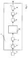
- FIG. 1 shows an electronic control unit 1, preferably a control unit for braking systems (for example ABS / ASC) in motor vehicles, which receives as input signal the speed signal S1 (FIG. 2) of a speed sensor 2, which has a specific number (z. B. 48) of equidistant teeth having encoder wheel (z. B. ABS pulse wheel, Fig. 2) cooperates.
- a rectangular speed signal S2 is generated from the sinusoidal signal S1, the frequency of which is proportional to the speed (called sinusoidal speed signal S1 for short).
- the rectangular pulse shaper 3 can also be contained in the sensor 2.
- the rectangular pulse shaper 3 is connected to a counter unit 4 (cf. also signal S3, FIG.
- the correction method of the method according to the invention is carried out in the correction unit 5.
- the output signal of the correction unit 5 is a speed signal which has been corrected by learning correction factors from errors which occur periodically over one revolution.
- This adjusted speed signal also contains the speed-independent frequencies of the useful signal component, in the present example the resonance frequencies of the wheel system. In order to evaluate these resonance frequencies, the adjusted speed signal is passed on to the frequency evaluation unit 7 via the bandpass filter 6.
- the frequency analysis unit 7 is by evaluating the zero crossings of x 0, filtered v i of the filtered velocity signal determines the actual resonance frequency of the wanted signal as well as the deviation of this actual resonant frequency of a predetermined desired resonant frequency.
- a change in the tire air pressure p is estimated as a function of the determined deviation and, for example, transmitted to a display or warning unit, not shown here.
- FIG. 3 shows the correction method for all 48 due to the correction method according to the invention Correction values or correction factors obtained for teeth of the encoder wheel shown.
- a division error is caused by the correction value assigned to tooth 15 F, which due to an uneven tooth width (see also signal S2 in Fig. 2) has been eliminated.
- the correction factors of all teeth one extending over one revolution, for example sinusoidal unbalance vibration, the frequency of which depends on the speed is eliminated.
- FIGS. 4 and 5 show the correction method for determining that shown in FIG. 3 Correction method explained in more detail.
- the average speed is recorded.
- the average speed i.e. the mean of the meter reading
- one Pulse before and after a pulse are calculated, whereby at least one division error is detected.
- Counter readings of a quarter turn used before and after whereby half a wheel revolution is detected. This allows both Pitch errors as well as wheel irregularity errors can be eliminated.
- advantage here is that the deviations from the average speed through Faults regardless of sections of the encoder wheel or ABS pulse wheel Getting corrected. Deviations that occur periodically with one wheel revolution are therefore have no influence on the speed values to be calculated.
- Fig. 4 are nine sample points P9, the counter readings as examples or correspond to the tooth values of nine of the 48 teeth per revolution, represented at one revolution. A tooth-related correction after a deviation is marked with arrows.
- an index i is assigned to each tooth of the pulse wheel. After a sensor threshold has been exceeded at a certain speed (eg v> 1 km / h), the assignment is established. It is important that the learned correction values are available within a few seconds if possible, which means that the detection of a pressure drop can be quickly ensured.
- the current and the last 24 recorded counter readings corresponding to half a wheel revolution are used for a possible design form of the method. It is assumed that the correction values of all teeth are recalculated every revolution and the assumption is made that the longitudinal acceleration of the vehicle changes only slightly in the short time interval under consideration.
- the correction factor k i-12 becomes the previously measured counter reading ⁇ i-12 (e.g. also P3; P4; P5; P6; P7, Fig. 4) calculated, which represents the counter reading a quarter of a revolution before.
- the calculation of the correction factors k i follows from the linear representation of the speed curve (FIG. 5) between the tooth value t i-24 corrected with the correction factor detected in this wheel revolution (e.g. also P1; P2; P3; P4; P5, Fig 4) and the tooth value t i , equation 2, corrected with the correction factor calculated from the previous revolution, a linear course is formed between the reference points i and i-24 .
- the detected counter reading i-12 is just placed on the linear line to this sampling point.
- the correction factor ⁇ 1-12 required for this is calculated by equation 2.
- ⁇ i-12 ⁇ i ⁇ (1 + k i ) ⁇ ⁇ t b + ⁇ i-24 ⁇ (1 + k i-24 ) ⁇ ⁇ t a ⁇ i-12 ⁇ ( ⁇ t b + ⁇ t a ) -1
- the correction factors are filtered, for example, in order to reduce the influence of the vehicle acceleration (ie no linear course of the straight line in FIG. 5) and the road profile.
- This filter calculates a weighted average between the correction factors of the current and previous revolution, equation 4.
- the factor a is adjusted during the duration of the process. At the beginning, a small value a ensures that the correct k value settles quickly; after a while the factor a is increased, which means that the useful signal is less filtered and the resolution and accuracy of the resonance frequency calculation is increased.
- the correction factors are continuously updated as they are speed-dependent,
- Fig. 3 shows the determined Correction factors after, for example, ten wheel revolutions. Clear the course of the deviations corresponding to one revolution is visible (F and vibration over one revolution).
- the initialization phase e.g. at the end of the line or after reassembly and balancing the wheel
- Serious changes to this picture or falling below a specified threshold of the correlation function between the currently recorded and saved state can be used to avoid an imbalance or other irregularity on the Lock the wheel.
- a warning algorithm can cause impermissible deviations detect this image from a target image and issue a warning, if the deviations fall below a certain correlation threshold.
- the corrected and averaged speed values preferably with a Bandpass filtered.
- the center frequency of the bandpass corresponds approximately to that resonant frequency of interest.
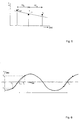
- a very quick method for determining a frequency in a filtered signal is the evaluation of the period.
- the time between two zero crossings (x 0, i ) (sign change of the signal) is calculated, the reciprocal value of which corresponds to the frequency of the signal.
- the sign changes from, for example, a negative value to a positive value the time corresponding to the zero crossing is approximately calculated with a linear relationship (Fig. 6).
- Fig. 6 There are various ways to record the correct signal frequency: you only evaluate positive zero crossings (one period), you only evaluate negative zero crossings (one period), you average between this positive and negative zero crossing or you evaluate the time between one negative-positive and positive-negative zero crossing off (half period).
- the value x 2 corresponds to the current time and can therefore be replaced by t 2 .
- the frequency of the filtered signal follows from the reciprocal of the difference between two successive positive or negative zero crossings, Equation 7, or from twice the value of half the period, Equation 8.
- f signal (t) 1 (x 0, i -x 0, i-1 )
- f signal (t) 1 ⁇ 2 ⁇ 1 (x 0, i -x 0, i-1 )
- a warning algorithm can impermissible deviations of the resonance frequencies from a target value detect and issue a warning if the calculated frequency is one falls below a certain threshold.
- the warning level remains in all except for ABS standard braking Preserve driving situations. You also get an overview of how Deviations in speed detection over one wheel revolution are distributed. These deviations can be evaluated or recorded a change in wheel irregularity (e.g. wheel imbalance or stone in the Profile %) can be used.
- wheel irregularity e.g. wheel imbalance or stone in the Profile
Landscapes
- Engineering & Computer Science (AREA)
- Physics & Mathematics (AREA)
- Mechanical Engineering (AREA)
- General Physics & Mathematics (AREA)
- Mathematical Physics (AREA)
- Transportation (AREA)
- Measuring Fluid Pressure (AREA)
- Transmission And Conversion Of Sensor Element Output (AREA)
Applications Claiming Priority (2)
| Application Number | Priority Date | Filing Date | Title |
|---|---|---|---|
| DE19735313A DE19735313B4 (de) | 1997-08-14 | 1997-08-14 | Verfahren zur Ermittlung von geschwindigkeitsunabhängigen Frequenzen eines Nutzsignalanteils |
| DE19735313 | 1997-08-14 |
Publications (3)
| Publication Number | Publication Date |
|---|---|
| EP0902292A2 true EP0902292A2 (fr) | 1999-03-17 |
| EP0902292A3 EP0902292A3 (fr) | 1999-08-11 |
| EP0902292B1 EP0902292B1 (fr) | 2003-12-10 |
Family
ID=7839010
Family Applications (1)
| Application Number | Title | Priority Date | Filing Date |
|---|---|---|---|
| EP98112646A Expired - Lifetime EP0902292B1 (fr) | 1997-08-14 | 1998-07-08 | Procédé de correction du signal d'un capteur de vitesse |
Country Status (2)
| Country | Link |
|---|---|
| EP (1) | EP0902292B1 (fr) |
| DE (2) | DE19735313B4 (fr) |
Cited By (6)
| Publication number | Priority date | Publication date | Assignee | Title |
|---|---|---|---|---|
| WO2003054556A1 (fr) * | 2001-12-08 | 2003-07-03 | Lucas Industries Limited | Capteur de vitesse angulaire |
| DE102013015705A1 (de) * | 2013-09-20 | 2015-03-26 | Audi Ag | Verfahren zur Ermittlung einer aktuellen Position eines Kraftfahrzeugs in einem geodätischen Koordinatensystem und Kraftfahrzeug |
| CN111137075A (zh) * | 2018-11-06 | 2020-05-12 | 现代自动车株式会社 | 用于估计轮胎共振频率的装置和方法 |
| WO2020192982A1 (fr) * | 2019-03-25 | 2020-10-01 | Robert Bosch Gmbh | Procédé et dispositif de détection d'un vissage de roue desserré sur une roue |
| CN114370932A (zh) * | 2020-10-16 | 2022-04-19 | 通用汽车环球科技运作有限责任公司 | 稳健轮胎/车轮振动监测器系统 |
| CN115754336A (zh) * | 2022-11-02 | 2023-03-07 | 国能(绥中)发电有限责任公司 | 转速信号处理方法和系统 |
Families Citing this family (10)
| Publication number | Priority date | Publication date | Assignee | Title |
|---|---|---|---|---|
| DE10148093A1 (de) * | 2001-09-28 | 2003-04-17 | Bayerische Motoren Werke Ag | Radkontrollsystem |
| DE102004037283B4 (de) | 2003-08-15 | 2018-04-05 | Continental Teves Ag & Co. Ohg | Verfahren zur Unterscheidung von Unwuchten an einer Felge und/oder einem Laufstreifen eines Fahrzeugrads |
| WO2005026744A1 (fr) * | 2003-09-11 | 2005-03-24 | Nsk Ltd. | Detecteur de vitesse de rotation et dispositif de mesure de charge avec unite support a roulement |
| CN103105503B (zh) * | 2012-12-13 | 2014-07-30 | 中国北车集团大连机车车辆有限公司 | 基于磁电式传感器的机车牵引电机转速信号的检测方法 |
| DE102014214538B4 (de) | 2014-07-24 | 2025-08-14 | Robert Bosch Gmbh | Verfahren zur Erleichterung der Entfernung von an Kraftfahrzeugreifen anhaftenden Gegenständen |
| US10254129B2 (en) | 2015-02-27 | 2019-04-09 | Infineon Technologies Ag | Low noise zero crossing detection for indirect tire pressure monitoring |
| DE102016201331A1 (de) | 2016-01-29 | 2017-08-03 | Robert Bosch Gmbh | Verfahren und Vorrichtung zur Detektion der azimutalen Winkelposition einer Radunwucht bei einem Rad an einem Fahrzeug |
| GB2555436B (en) * | 2016-10-27 | 2019-05-08 | Delphi Tech Ip Ltd | Method to determine tooth error in period of one or more teeth of a rotating toothed wheel |
| CN106680531B (zh) * | 2017-01-23 | 2019-07-30 | 中国核动力研究设计院 | 一种高可靠性核电领域泵速测量装置 |
| FR3066721B1 (fr) * | 2017-05-23 | 2019-06-07 | Continental Automotive France | Procede d'identification d'au moins un emetteur de surveillance de la pression d'un pneumatique d'un vehicule automobile par association avec une des roues dudit vehicule automobile |
Family Cites Families (15)
| Publication number | Priority date | Publication date | Assignee | Title |
|---|---|---|---|---|
| DE2915815A1 (de) * | 1979-04-19 | 1980-11-06 | Bauknecht Gmbh G | Vorrichtung zum erfassen der drehzahl und der unwucht eines in einem gehaeuse schwingend gelagerten aggregates |
| DE3425472A1 (de) * | 1984-07-11 | 1986-01-23 | Licentia Patent-Verwaltungs-Gmbh, 6000 Frankfurt | Verfahren und vorrichtung zur digitalen bestimmung der zahl der umdrehungen sich drehender koerper |
| DE3543058C2 (de) * | 1985-12-05 | 1997-02-13 | Teves Gmbh Alfred | Verfahren und Schaltungsanordnung zur Aufbereitung eines Sensorsignals |
| JP2588219B2 (ja) * | 1987-11-17 | 1997-03-05 | 日産自動車株式会社 | 車輸速センサの検出値補正装置 |
| US4907452A (en) * | 1988-10-05 | 1990-03-13 | Ford Motor Company | System for detecting rotational imbalance of vehicle roadwheels |
| DE3937403A1 (de) * | 1989-11-10 | 1991-05-16 | Porsche Ag | Verfahren und einrichtung zur ueberwachung der funktionstuechtigkeit eines fahrwerks fuer ein kraftfahrzeug |
| US5117681A (en) * | 1990-10-01 | 1992-06-02 | Ford Motor Company | Correction of systematic position-sensing errors in internal combustion engines |
| DE4208989A1 (de) * | 1992-03-20 | 1993-09-23 | Philips Patentverwaltung | Verfahren zur detektion und kompensation einer unwucht bei einem durch einen motor angetriebenen rotor |
| US5541859A (en) * | 1993-03-23 | 1996-07-30 | Nippondenso Co., Ltd. | Speed detecting apparatus for rotating body |
| DE4330617A1 (de) * | 1993-09-09 | 1995-03-16 | Bayerische Motoren Werke Ag | Verfahren zur Bestimmung des Reifenluftdrucks von Fahrzeugrädern |
| DE4406606A1 (de) * | 1994-03-01 | 1995-09-07 | Audi Ag | Adaptionsvorrichtung für ein Geberrad an einem Verbrennungsmotor |
| GB9413677D0 (en) * | 1994-07-07 | 1994-08-24 | Lucas Ind Plc | Method of and apparatus for calibrating rotary position transducers |
| DE69510287T2 (de) * | 1994-09-09 | 2000-03-23 | Denso Corp., Kariya | Pneumatischer Reifendruckmesser |
| JP3175552B2 (ja) * | 1995-08-04 | 2001-06-11 | 株式会社デンソー | タイヤ空気圧推定装置 |
| DE19540674C2 (de) * | 1995-10-31 | 1999-01-28 | Siemens Ag | Adaptionsverfahren zur Korrektur von Toleranzen eines Geberrades |
-
1997
- 1997-08-14 DE DE19735313A patent/DE19735313B4/de not_active Expired - Fee Related
-
1998
- 1998-07-08 DE DE59810385T patent/DE59810385D1/de not_active Expired - Lifetime
- 1998-07-08 EP EP98112646A patent/EP0902292B1/fr not_active Expired - Lifetime
Cited By (10)
| Publication number | Priority date | Publication date | Assignee | Title |
|---|---|---|---|---|
| WO2003054556A1 (fr) * | 2001-12-08 | 2003-07-03 | Lucas Industries Limited | Capteur de vitesse angulaire |
| US6958599B2 (en) | 2001-12-08 | 2005-10-25 | Lucas Industries Limited | Angular velocity sensor |
| DE102013015705A1 (de) * | 2013-09-20 | 2015-03-26 | Audi Ag | Verfahren zur Ermittlung einer aktuellen Position eines Kraftfahrzeugs in einem geodätischen Koordinatensystem und Kraftfahrzeug |
| DE102013015705B4 (de) * | 2013-09-20 | 2019-12-05 | Audi Ag | Verfahren zur Ermittlung einer aktuellen Position eines Kraftfahrzeugs in einem geodätischen Koordinatensystem und Kraftfahrzeug |
| CN111137075A (zh) * | 2018-11-06 | 2020-05-12 | 现代自动车株式会社 | 用于估计轮胎共振频率的装置和方法 |
| WO2020192982A1 (fr) * | 2019-03-25 | 2020-10-01 | Robert Bosch Gmbh | Procédé et dispositif de détection d'un vissage de roue desserré sur une roue |
| US11953370B2 (en) | 2019-03-25 | 2024-04-09 | Robert Bosch Gmbh | Method and device for detecting a loosened bolted wheel joint on a wheel |
| CN114370932A (zh) * | 2020-10-16 | 2022-04-19 | 通用汽车环球科技运作有限责任公司 | 稳健轮胎/车轮振动监测器系统 |
| US11815426B2 (en) | 2020-10-16 | 2023-11-14 | GM Global Technology Operations LLC | Robust tire/wheel vibration monitor system |
| CN115754336A (zh) * | 2022-11-02 | 2023-03-07 | 国能(绥中)发电有限责任公司 | 转速信号处理方法和系统 |
Also Published As
| Publication number | Publication date |
|---|---|
| EP0902292B1 (fr) | 2003-12-10 |
| DE59810385D1 (de) | 2004-01-22 |
| DE19735313B4 (de) | 2008-02-07 |
| EP0902292A3 (fr) | 1999-08-11 |
| DE19735313A1 (de) | 1999-02-18 |
Similar Documents
| Publication | Publication Date | Title |
|---|---|---|
| EP0902292B1 (fr) | Procédé de correction du signal d'un capteur de vitesse | |
| EP0933237B1 (fr) | Procédé pour surveiller la pression d'un pneumatique d'un véhicule | |
| EP1646515B1 (fr) | Procedes pour determiner la pression interieure d'un pneu de vehicule | |
| EP2250037B1 (fr) | Procédé de détermination du chargement d'un véhicule | |
| DE602004013044T2 (de) | Fahrbahnzustandserfassungsvorrichtung und -verfahren in einem kraftfahrzeug | |
| EP0938987A2 (fr) | Méthode et appareil de surveillance de la pression des pneumatiques d'un véhicule automobile | |
| DE69716542T2 (de) | Sensor von Reifenfehlern | |
| DE102010000867A1 (de) | Verfahren zur Ermittlung eines aktualisierten Radumfangs | |
| DE19537257A1 (de) | Verfahren zur Ermittlung des physikalischen Profils einer Fahrbahnoberfläche | |
| DE4035370A1 (de) | Verfahren zur bestimmung des standortes eines landfahrzeugs | |
| DE102009012128B4 (de) | Verfahren zum Bestimmen einer Rauigkeit einer Fahrbahnoberfläche für ein Fahrzeug | |
| EP2849979B1 (fr) | Procédé et dispositif de détermination de la circonférence d'un pneumatique monté sur un véhicule | |
| EP1304576A2 (fr) | Procédé de surveillance de l'état d'une roue d'un véhicule automobile | |
| EP1216177B1 (fr) | Dispositif capteur de pneu | |
| EP1162443A2 (fr) | Méthode et dispositif pour reconnaítre les dommages causés dans les absorbers | |
| DE19963751A1 (de) | Verfahren zum Untersuchen von Reifen von Fahrzeugen im Fahrbetrieb | |
| EP3410081B1 (fr) | Détermination de la valeur efficace d'une mesurande de vibration d'une machine | |
| WO2005123423A2 (fr) | Systeme de detection d'une chute de pression sur le pneu d'un vehicule | |
| DE102005050206A1 (de) | Verfahren und Vorrichtung zur Bestimmung der Wegstrecke und/oder Geschwindigkeit eines Kraftfahrzeuges | |
| DE102015212944A1 (de) | Verfahren und Vorrichtung zum Ermitteln von Drehwinkelgeschwindigkeiten und/oder Drehwinkelpositionen von Fahrzeugrädern eines Kraftfahrzeuges, sowie zum Lokalisieren der Verbaupositionen von an den Fahrzeugrädern angeordneten Radeinheiten | |
| DE102007030432B4 (de) | Verfahren zur Drehrichtungserkennung eines Encoders | |
| DE102008054393A1 (de) | Verfahren und Vorrichtung zur Ermittlung der Drehrichtung eines Reifens mittels zweier Beschleunigungssensoren mit unterschiedlicher Detektionsrichtung | |
| DE102022210834B4 (de) | Straßenunebenheitserfassung durch Auswertung des Betriebsstroms eines elektrischen Fahrzeugantriebs | |
| DE102005049442A1 (de) | System zur Erkennung eines Reifendruckverlustes bei Kraftfahrzeugen | |
| DE10044287A1 (de) | Reifensensor |
Legal Events
| Date | Code | Title | Description |
|---|---|---|---|
| PUAI | Public reference made under article 153(3) epc to a published international application that has entered the european phase |
Free format text: ORIGINAL CODE: 0009012 |
|
| AK | Designated contracting states |
Kind code of ref document: A2 Designated state(s): DE FR GB |
|
| AX | Request for extension of the european patent |
Free format text: AL;LT;LV;MK;RO;SI |
|
| PUAL | Search report despatched |
Free format text: ORIGINAL CODE: 0009013 |
|
| AK | Designated contracting states |
Kind code of ref document: A3 Designated state(s): AT BE CH CY DE DK ES FI FR GB GR IE IT LI LU MC NL PT SE |
|
| AX | Request for extension of the european patent |
Free format text: AL;LT;LV;MK;RO;SI |
|
| RIC1 | Information provided on ipc code assigned before grant |
Free format text: 6G 01P 21/02 A, 6G 01P 3/489 B, 6G 01D 18/00 B, 6B 60C 23/06 B |
|
| 17P | Request for examination filed |
Effective date: 20000202 |
|
| AKX | Designation fees paid |
Free format text: DE FR GB |
|
| 17Q | First examination report despatched |
Effective date: 20020729 |
|
| GRAH | Despatch of communication of intention to grant a patent |
Free format text: ORIGINAL CODE: EPIDOS IGRA |
|
| GRAS | Grant fee paid |
Free format text: ORIGINAL CODE: EPIDOSNIGR3 |
|
| GRAA | (expected) grant |
Free format text: ORIGINAL CODE: 0009210 |
|
| AK | Designated contracting states |
Kind code of ref document: B1 Designated state(s): DE FR GB |
|
| REG | Reference to a national code |
Ref country code: GB Ref legal event code: FG4D Free format text: NOT ENGLISH |
|
| GBT | Gb: translation of ep patent filed (gb section 77(6)(a)/1977) |
Effective date: 20031210 |
|
| REF | Corresponds to: |
Ref document number: 59810385 Country of ref document: DE Date of ref document: 20040122 Kind code of ref document: P |
|
| ET | Fr: translation filed | ||
| PLBE | No opposition filed within time limit |
Free format text: ORIGINAL CODE: 0009261 |
|
| STAA | Information on the status of an ep patent application or granted ep patent |
Free format text: STATUS: NO OPPOSITION FILED WITHIN TIME LIMIT |
|
| 26N | No opposition filed |
Effective date: 20040913 |
|
| PGFP | Annual fee paid to national office [announced via postgrant information from national office to epo] |
Ref country code: GB Payment date: 20070726 Year of fee payment: 10 |
|
| PGFP | Annual fee paid to national office [announced via postgrant information from national office to epo] |
Ref country code: FR Payment date: 20070730 Year of fee payment: 10 |
|
| GBPC | Gb: european patent ceased through non-payment of renewal fee |
Effective date: 20080708 |
|
| REG | Reference to a national code |
Ref country code: FR Ref legal event code: ST Effective date: 20090331 |
|
| PG25 | Lapsed in a contracting state [announced via postgrant information from national office to epo] |
Ref country code: GB Free format text: LAPSE BECAUSE OF NON-PAYMENT OF DUE FEES Effective date: 20080708 |
|
| PG25 | Lapsed in a contracting state [announced via postgrant information from national office to epo] |
Ref country code: FR Free format text: LAPSE BECAUSE OF NON-PAYMENT OF DUE FEES Effective date: 20080731 |
|
| PGFP | Annual fee paid to national office [announced via postgrant information from national office to epo] |
Ref country code: DE Payment date: 20140725 Year of fee payment: 17 |
|
| REG | Reference to a national code |
Ref country code: DE Ref legal event code: R119 Ref document number: 59810385 Country of ref document: DE |
|
| PG25 | Lapsed in a contracting state [announced via postgrant information from national office to epo] |
Ref country code: DE Free format text: LAPSE BECAUSE OF NON-PAYMENT OF DUE FEES Effective date: 20160202 |