EP0902190A2 - Vakuumpumpen - Google Patents
Vakuumpumpen Download PDFInfo
- Publication number
- EP0902190A2 EP0902190A2 EP98307285A EP98307285A EP0902190A2 EP 0902190 A2 EP0902190 A2 EP 0902190A2 EP 98307285 A EP98307285 A EP 98307285A EP 98307285 A EP98307285 A EP 98307285A EP 0902190 A2 EP0902190 A2 EP 0902190A2
- Authority
- EP
- European Patent Office
- Prior art keywords
- stage
- blades
- turbo
- rotor
- pump
- Prior art date
- Legal status (The legal status is an assumption and is not a legal conclusion. Google has not performed a legal analysis and makes no representation as to the accuracy of the status listed.)
- Granted
Links
- 238000000926 separation method Methods 0.000 claims description 5
- 239000007789 gas Substances 0.000 description 28
- 230000006835 compression Effects 0.000 description 9
- 238000007906 compression Methods 0.000 description 9
- 230000007246 mechanism Effects 0.000 description 7
- 238000005086 pumping Methods 0.000 description 6
- 150000001875 compounds Chemical class 0.000 description 5
- 230000005540 biological transmission Effects 0.000 description 4
- 239000007787 solid Substances 0.000 description 3
- 230000000694 effects Effects 0.000 description 2
- 230000002411 adverse Effects 0.000 description 1
- 238000010348 incorporation Methods 0.000 description 1
- 230000037361 pathway Effects 0.000 description 1
- 230000001172 regenerating effect Effects 0.000 description 1
- 238000009987 spinning Methods 0.000 description 1
- 238000011144 upstream manufacturing Methods 0.000 description 1
Images

Classifications
-
- F—MECHANICAL ENGINEERING; LIGHTING; HEATING; WEAPONS; BLASTING
- F04—POSITIVE - DISPLACEMENT MACHINES FOR LIQUIDS; PUMPS FOR LIQUIDS OR ELASTIC FLUIDS
- F04D—NON-POSITIVE-DISPLACEMENT PUMPS
- F04D19/00—Axial-flow pumps
- F04D19/02—Multi-stage pumps
- F04D19/04—Multi-stage pumps specially adapted to the production of a high vacuum, e.g. molecular pumps
- F04D19/042—Turbomolecular vacuum pumps
-
- F—MECHANICAL ENGINEERING; LIGHTING; HEATING; WEAPONS; BLASTING
- F04—POSITIVE - DISPLACEMENT MACHINES FOR LIQUIDS; PUMPS FOR LIQUIDS OR ELASTIC FLUIDS
- F04D—NON-POSITIVE-DISPLACEMENT PUMPS
- F04D29/00—Details, component parts, or accessories
- F04D29/40—Casings; Connections of working fluid
- F04D29/52—Casings; Connections of working fluid for axial pumps
- F04D29/54—Fluid-guiding means, e.g. diffusers
- F04D29/541—Specially adapted for elastic fluid pumps
- F04D29/542—Bladed diffusers
- F04D29/544—Blade shapes
Definitions
- This invention relates to vacuum pump and, more particularly, to vacuum pumps comprising or incorporating turbo-molecular pumping stages.
- a conventional turbo-molecular stage arrangement of a vacuum pump comprises a stack of alternate rotors and stators.
- Each stage effectively comprises a solid disc with a plurality of blades depending (nominally) radially therefrom; the blades are evenly spaced around the circumference of the disc and angled "about" radial lines out of the plane of the disc in the direction of rotation of the rotor stage.
- the rotor and stator blades have positive and negative gradients respectively when viewed from the side in to a radial line of the disc. This arrangement has the effect in highly viscous flow conditions of causing rapid changes in the flow direction, resulting in high power consumption.
- Turbo-molecular vacuum pumps are designed to operate at high rotational speeds of the shaft to which the rotor discs are attached and to achieve high levels of vacuum in the chambers to which they are attached.
- Turbo-molecular pumps are generally unable to deliver gases directly to the atmosphere; the use of a backing pump of different pumping mechanism which pumps down or "roughs" the pressure in the chamber, preferably prior to the operation of the turbo-molecular pump, and in to the inlet of which the output of the turbo-molecular pump is subsequently directed, is therefore generally needed.
- the backing pump may alternatively be incorporated in to the turbo-molecular pump body to form a compound vacuum pump.
- the turbo-molecular pump stages may be followed, in order of gas flow through the pump as a whole, by one or more molecular drag stages, for example those known as "Gaede” stages or “Holweck” stages, and regenerative stages to exhaust to atmospheric pressure.
- a compound design incorporates the different pump stages/mechanisms, the rotors of which are all rigidly mounted on a single shaft and each mechanism being suited to pumping in different vacuum pressure regions. As such, the combination of mechanisms provide a steady pressure gradient through the pump as a whole from inlet to outlet.
- the mechanisms suited to pumping in viscous flow conditions begin to reduce the upstream pressure in the pump and thereby reduce the power required to rotate the turbo-molecular blades.
- the shaft speed can then increase and the pressure at the pump inlet can reduce further.
- a turbo-molecular vacuum pump comprising alternate first and second stages in which the first stage comprises a plurality of blades arranged in an annular envelope with the blades depending radially from a disc and angled about radial lines out of the plane of the disc and the second stage comprises a plurality of co-axial, concentric frusto-conical members arrayed in a plane parallel to that of the annular envelope such that at least some of the blades and at least some of the frusto-conical members are axially aligned and are adapted to remain so during rotation of one stage relative to the other.
- the rotor stage is attached to, and arrayed centrally about, a pump shaft adapted for rotation at high speed about its main axis, and the stator stage is attached to the pump body and also arrayed centrally about the main axis of the pump shaft.
- the first stage comprises the rotor and the second stage (frusto-conical members) comprises the stator and the radially depending blades are angled about the radial lines of the disc in a direction of rotation of the rotor, i.e. such that gas molecules passing through the first stage are urged through the pump.
- stages and a reverse arrangement of the stages as stator and rotor requires a significantly reduced power consumption for atmospheric pressure operation but, surprisingly without significant loss of overall performance at lower pressure (higher vacuum) operation.
- Each stage achieves the two basic previously stated functions required of them, i.e. to provide compression and to redirect molecules.
- the radial stage(s) behave in substantially identical fashion to conventional radial blades, generating compression and providing suitable gas molecule direction.
- the conical stage(s) also aid re-direction of the gas molecules between the radial stages to support the relative velocity requirements which enable the radial stages to operate effectively.
- the radial component of velocity entering the conical stage is significantly lower than the tangential rotor velocity and, as a result, a compression will be generated but will be somewhat lower than for the radial blades of a conventional design of pump. The reduction does not, however, reduce the acceptability of overall pump performance.
- the pump of the invention can be improved further by allowing a greater separation between the blades of the first stage and the conical members of the second stage, for example increased from the spacing in a conventional pump of 3mm to 4mm to a higher spacing of up to 10mm, for example 5mm to 10mm. This allows gas molecules to possess a higher proportion of radial velocity before entering the conical stator members and further reduces the shear generated in viscous flow.
- the blades of the rotor stage may be angled, in addition to that effected in a circumferential direction relative to a plane of the ring in they are arrayed, to sweep back so that their main axes no longer lie on a radial line. This generates a non-tangential trajectory bias for the molecules leaving the blades, thereby increasing the radial velocity component in to the conical members and improving pumping performance overall.
- Figure 1 is schematic perspective view of a vacuum pump of the invention showing part of a radial blade stage and a conical stage.
- Figure 2 is a plan view of the pump shown in Figure 1.
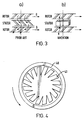
- Figure 3 shows schematically a conventional turbo-molecular pump and b) a vacuum pump of the invention.
- Figure 4 is a plan view of a modified blade stage rotor in accordance with the invention.
- a vacuum pump of the invention comprising a pump body 1 of circular cross section and having mounted therein by bearing means (not shown) a shaft 2 which is adapted for rotation at high speed about its longitudinal axis (and that of the body 1) by a motor (not shown).
- a second stage 5 - the stator stage - comprising a solid disc 6 having a central aperture within which the shaft rotates, which is surrounded in a radial plane by a plurality (three) of co-axial, concentric, frusto-conical, hollow members 7 and an outer member 8; the outer member 8 is of circular cross section and is fixed to the inside surface of the body 1.
- the members 7 and 8 and the disc 6 are held stationary in a radial plane (at right angles to the shaft axis) by means of linking struts not shown. Angled, evenly-spaced annular gaps are therefore formed between the members 7 and 8 and the disc 6 a shown most clearly in Figure 1.
- Figure 3 shows, in the prior art left-hand part a) the direction of flow of gas through a three stage conventional pump arrangement, i.e. each stage comprising blades angled in alternate fashion from stage to stage with the two rotor stages moving in the direction of the arrows B.
- the flow is in accordance with the general prior art description provided in the introduction above.
- Part b) of Figure 3 shows the direction of flow through two rotor stages and a stator stage of a pump of the invention, again in accordance with the general invention description provided in the introduction above.
Landscapes
- Engineering & Computer Science (AREA)
- Mechanical Engineering (AREA)
- General Engineering & Computer Science (AREA)
- Physics & Mathematics (AREA)
- Geometry (AREA)
- Non-Positive Displacement Air Blowers (AREA)
- Structures Of Non-Positive Displacement Pumps (AREA)
Applications Claiming Priority (2)
| Application Number | Priority Date | Filing Date | Title |
|---|---|---|---|
| GB9719634 | 1997-09-15 | ||
| GBGB9719634.9A GB9719634D0 (en) | 1997-09-15 | 1997-09-15 | Improvements in vacuum pumps |
Publications (3)
| Publication Number | Publication Date |
|---|---|
| EP0902190A2 true EP0902190A2 (de) | 1999-03-17 |
| EP0902190A3 EP0902190A3 (de) | 1999-11-24 |
| EP0902190B1 EP0902190B1 (de) | 2004-01-02 |
Family
ID=10819113
Family Applications (1)
| Application Number | Title | Priority Date | Filing Date |
|---|---|---|---|
| EP98307285A Expired - Lifetime EP0902190B1 (de) | 1997-09-15 | 1998-09-09 | Vakuumpumpen |
Country Status (5)
| Country | Link |
|---|---|
| US (1) | US6109864A (de) |
| EP (1) | EP0902190B1 (de) |
| JP (1) | JP4195743B2 (de) |
| DE (1) | DE69820824T2 (de) |
| GB (1) | GB9719634D0 (de) |
Cited By (2)
| Publication number | Priority date | Publication date | Assignee | Title |
|---|---|---|---|---|
| RU2378028C1 (ru) * | 2005-09-09 | 2010-01-10 | Груп Леадер Са | Вентилятор для тушения пожаров, содержащий устройство для выравнивания потока воздуха |
| CN102295138A (zh) * | 2011-09-22 | 2011-12-28 | 长沙中联重工科技发展股份有限公司 | 提升机的链轮轴安装结构及沥青搅拌站的提升机 |
Families Citing this family (12)
| Publication number | Priority date | Publication date | Assignee | Title |
|---|---|---|---|---|
| JP4066282B2 (ja) * | 1998-05-26 | 2008-03-26 | 株式会社安川電機 | 電気機器 |
| US6595753B1 (en) * | 1999-05-21 | 2003-07-22 | A. Vortex Holding Company | Vortex attractor |
| GB9921983D0 (en) * | 1999-09-16 | 1999-11-17 | Boc Group Plc | Improvements in vacuum pumps |
| US6508631B1 (en) * | 1999-11-18 | 2003-01-21 | Mks Instruments, Inc. | Radial flow turbomolecular vacuum pump |
| TW511880U (en) * | 2002-01-18 | 2002-11-21 | Foxconn Prec Components Co Ltd | Assembly of heat dissipation apparatus |
| US7500822B2 (en) * | 2004-04-09 | 2009-03-10 | Edwards Vacuum, Inc. | Combined vacuum pump load-lock assembly |
| US20070020115A1 (en) * | 2005-07-01 | 2007-01-25 | The Boc Group, Inc. | Integrated pump apparatus for semiconductor processing |
| CN1932302B (zh) * | 2005-09-12 | 2012-04-25 | 建准电机工业股份有限公司 | 具导流出风口的散热扇 |
| US20070081893A1 (en) * | 2005-10-06 | 2007-04-12 | The Boc Group, Inc. | Pump apparatus for semiconductor processing |
| GB2498816A (en) * | 2012-01-27 | 2013-07-31 | Edwards Ltd | Vacuum pump |
| DE102018119747B3 (de) * | 2018-08-14 | 2020-02-13 | Bruker Daltonik Gmbh | Turbomolekularpumpe für massenspektrometer |
| US11519419B2 (en) * | 2020-04-15 | 2022-12-06 | Kin-Chung Ray Chiu | Non-sealed vacuum pump with supersonically rotatable bladeless gas impingement surface |
Family Cites Families (8)
| Publication number | Priority date | Publication date | Assignee | Title |
|---|---|---|---|---|
| US940103A (en) * | 1909-08-31 | 1909-11-16 | Walther Feld | Gas-washer. |
| FR847018A (fr) * | 1937-12-06 | 1939-10-02 | Brandenburgische Motorenwerke | Soufflerie ou pompe à hélice |
| US2653757A (en) * | 1950-08-09 | 1953-09-29 | Segalman Bernard | Diffuser for ventilating fans |
| JPS57168097A (en) * | 1981-04-10 | 1982-10-16 | Hitachi Ltd | Capacity control device |
| US4655680A (en) * | 1983-06-06 | 1987-04-07 | Klepesch Philip H | Continuous blade axial-flow friction drag pump |
| SU1366709A1 (ru) * | 1986-03-05 | 1988-01-15 | МВТУ им.Н.Э.Баумана | Турбомолекул рный вакуумный насос |
| DE3891263T1 (de) * | 1988-02-26 | 1990-03-15 | Nikolaj Michailovic Novikov | Turbomolekular-vakuumpumpe |
| JPH0680318B2 (ja) * | 1988-05-30 | 1994-10-12 | ダイキン工業株式会社 | 多板型送風機 |
-
1997
- 1997-09-15 GB GBGB9719634.9A patent/GB9719634D0/en not_active Ceased
-
1998
- 1998-09-09 DE DE69820824T patent/DE69820824T2/de not_active Expired - Lifetime
- 1998-09-09 EP EP98307285A patent/EP0902190B1/de not_active Expired - Lifetime
- 1998-09-11 US US09/151,630 patent/US6109864A/en not_active Expired - Lifetime
- 1998-09-16 JP JP26113098A patent/JP4195743B2/ja not_active Expired - Fee Related
Cited By (3)
| Publication number | Priority date | Publication date | Assignee | Title |
|---|---|---|---|---|
| RU2378028C1 (ru) * | 2005-09-09 | 2010-01-10 | Груп Леадер Са | Вентилятор для тушения пожаров, содержащий устройство для выравнивания потока воздуха |
| CN102295138A (zh) * | 2011-09-22 | 2011-12-28 | 长沙中联重工科技发展股份有限公司 | 提升机的链轮轴安装结构及沥青搅拌站的提升机 |
| CN102295138B (zh) * | 2011-09-22 | 2013-04-03 | 中联重科股份有限公司 | 提升机的链轮轴安装结构及沥青搅拌站的提升机 |
Also Published As
| Publication number | Publication date |
|---|---|
| US6109864A (en) | 2000-08-29 |
| JP4195743B2 (ja) | 2008-12-10 |
| DE69820824D1 (de) | 2004-02-05 |
| JPH11148485A (ja) | 1999-06-02 |
| DE69820824T2 (de) | 2004-12-09 |
| GB9719634D0 (en) | 1997-11-19 |
| EP0902190B1 (de) | 2004-01-02 |
| EP0902190A3 (de) | 1999-11-24 |
Similar Documents
| Publication | Publication Date | Title |
|---|---|---|
| JP4395210B2 (ja) | 真空ポンプの改良 | |
| EP0902190B1 (de) | Vakuumpumpen | |
| US6135709A (en) | Vacuum pump | |
| EP1068456B1 (de) | Vakuumpumpen mit doppeltem eintritt | |
| JP2003129990A (ja) | 真空ポンプ | |
| US5611660A (en) | Compound vacuum pumps | |
| JPH04224295A (ja) | ターボ分子ポンプ | |
| JPH09177695A (ja) | 真空ポンプ | |
| JP4667043B2 (ja) | 真空ポンプ排出装置 | |
| US6394747B1 (en) | Molecular drag vacuum pumps | |
| WO2015098275A1 (ja) | 真空排気機構、複合型真空ポンプ、および回転体部品 | |
| JP4104098B2 (ja) | 真空ポンプ | |
| CA2563241C (en) | Vacuum pump | |
| US6371735B1 (en) | Vacuum pumps | |
| EP0142208B1 (de) | Molekularpumpe für Hochvakuum | |
| US6890146B2 (en) | Compound friction vacuum pump | |
| JPS6355396A (ja) | タ−ボ真空ポンプ | |
| US8105013B2 (en) | Vacuum pump | |
| CN216922541U (zh) | 真空系统 | |
| JPH03237295A (ja) | ターボ分子ポンプ | |
| US6971840B2 (en) | Method of enhancing the aerodynamic performance of a fan | |
| JPH11159493A (ja) | フィン付きロータ構造を有する分子抗力圧縮機 | |
| JPS6245997A (ja) | タ−ボ分子ポンプ | |
| JPH065077B2 (ja) | ターボ分子ポンプ | |
| JPH065076B2 (ja) | ターボ分子ポンプ |
Legal Events
| Date | Code | Title | Description |
|---|---|---|---|
| PUAI | Public reference made under article 153(3) epc to a published international application that has entered the european phase |
Free format text: ORIGINAL CODE: 0009012 |
|
| AK | Designated contracting states |
Kind code of ref document: A2 Designated state(s): CH DE FR GB LI |
|
| AX | Request for extension of the european patent |
Free format text: AL;LT;LV;MK;RO;SI |
|
| PUAL | Search report despatched |
Free format text: ORIGINAL CODE: 0009013 |
|
| AK | Designated contracting states |
Kind code of ref document: A3 Designated state(s): AT BE CH CY DE DK ES FI FR GB GR IE IT LI LU MC NL PT SE |
|
| AX | Request for extension of the european patent |
Free format text: AL;LT;LV;MK;RO;SI |
|
| RIC1 | Information provided on ipc code assigned before grant |
Free format text: 6F 04D 19/04 A, 6F 04D 29/54 B |
|
| 17P | Request for examination filed |
Effective date: 20000417 |
|
| AKX | Designation fees paid |
Free format text: CH DE FR GB LI |
|
| 17Q | First examination report despatched |
Effective date: 20021113 |
|
| GRAP | Despatch of communication of intention to grant a patent |
Free format text: ORIGINAL CODE: EPIDOSNIGR1 |
|
| GRAS | Grant fee paid |
Free format text: ORIGINAL CODE: EPIDOSNIGR3 |
|
| GRAA | (expected) grant |
Free format text: ORIGINAL CODE: 0009210 |
|
| AK | Designated contracting states |
Kind code of ref document: B1 Designated state(s): CH DE FR GB LI |
|
| REG | Reference to a national code |
Ref country code: GB Ref legal event code: FG4D |
|
| REG | Reference to a national code |
Ref country code: CH Ref legal event code: EP |
|
| REF | Corresponds to: |
Ref document number: 69820824 Country of ref document: DE Date of ref document: 20040205 Kind code of ref document: P |
|
| REG | Reference to a national code |
Ref country code: CH Ref legal event code: NV Representative=s name: RIEDERER HASLER & PARTNER PATENTANWAELTE AG |
|
| ET | Fr: translation filed | ||
| PLBE | No opposition filed within time limit |
Free format text: ORIGINAL CODE: 0009261 |
|
| STAA | Information on the status of an ep patent application or granted ep patent |
Free format text: STATUS: NO OPPOSITION FILED WITHIN TIME LIMIT |
|
| 26N | No opposition filed |
Effective date: 20041005 |
|
| REG | Reference to a national code |
Ref country code: GB Ref legal event code: 732E |
|
| REG | Reference to a national code |
Ref country code: CH Ref legal event code: PUE Owner name: EDWARDS LIMITED Free format text: THE BOC GROUP PLC#CHERTSEY ROAD#WINDLESHAM SURREY GU20 6HJ (GB) -TRANSFER TO- EDWARDS LIMITED#MANOR ROYAL#CRAWLEY WEST SUSSEX RH10 9LW (GB) |
|
| REG | Reference to a national code |
Ref country code: FR Ref legal event code: TP |
|
| PGFP | Annual fee paid to national office [announced via postgrant information from national office to epo] |
Ref country code: CH Payment date: 20080930 Year of fee payment: 11 |
|
| PGFP | Annual fee paid to national office [announced via postgrant information from national office to epo] |
Ref country code: FR Payment date: 20080917 Year of fee payment: 11 |
|
| PGFP | Annual fee paid to national office [announced via postgrant information from national office to epo] |
Ref country code: GB Payment date: 20080929 Year of fee payment: 11 |
|
| REG | Reference to a national code |
Ref country code: CH Ref legal event code: PL |
|
| GBPC | Gb: european patent ceased through non-payment of renewal fee |
Effective date: 20090909 |
|
| REG | Reference to a national code |
Ref country code: FR Ref legal event code: ST Effective date: 20100531 |
|
| PG25 | Lapsed in a contracting state [announced via postgrant information from national office to epo] |
Ref country code: FR Free format text: LAPSE BECAUSE OF NON-PAYMENT OF DUE FEES Effective date: 20090930 |
|
| PG25 | Lapsed in a contracting state [announced via postgrant information from national office to epo] |
Ref country code: LI Free format text: LAPSE BECAUSE OF NON-PAYMENT OF DUE FEES Effective date: 20090930 Ref country code: CH Free format text: LAPSE BECAUSE OF NON-PAYMENT OF DUE FEES Effective date: 20090930 |
|
| PG25 | Lapsed in a contracting state [announced via postgrant information from national office to epo] |
Ref country code: GB Free format text: LAPSE BECAUSE OF NON-PAYMENT OF DUE FEES Effective date: 20090909 |
|
| PGFP | Annual fee paid to national office [announced via postgrant information from national office to epo] |
Ref country code: DE Payment date: 20140929 Year of fee payment: 17 |
|
| REG | Reference to a national code |
Ref country code: DE Ref legal event code: R119 Ref document number: 69820824 Country of ref document: DE |
|
| PG25 | Lapsed in a contracting state [announced via postgrant information from national office to epo] |
Ref country code: DE Free format text: LAPSE BECAUSE OF NON-PAYMENT OF DUE FEES Effective date: 20160401 |