EP0902166A2 - Erosionsschutzschild in einer Luftströmung - Google Patents
Erosionsschutzschild in einer Luftströmung Download PDFInfo
- Publication number
- EP0902166A2 EP0902166A2 EP98307380A EP98307380A EP0902166A2 EP 0902166 A2 EP0902166 A2 EP 0902166A2 EP 98307380 A EP98307380 A EP 98307380A EP 98307380 A EP98307380 A EP 98307380A EP 0902166 A2 EP0902166 A2 EP 0902166A2
- Authority
- EP
- European Patent Office
- Prior art keywords
- particulates
- erosion
- gas flow
- turbine
- orifice
- Prior art date
- Legal status (The legal status is an assumption and is not a legal conclusion. Google has not performed a legal analysis and makes no representation as to the accuracy of the status listed.)
- Granted
Links
Images

Classifications
-
- F—MECHANICAL ENGINEERING; LIGHTING; HEATING; WEAPONS; BLASTING
- F02—COMBUSTION ENGINES; HOT-GAS OR COMBUSTION-PRODUCT ENGINE PLANTS
- F02C—GAS-TURBINE PLANTS; AIR INTAKES FOR JET-PROPULSION PLANTS; CONTROLLING FUEL SUPPLY IN AIR-BREATHING JET-PROPULSION PLANTS
- F02C7/00—Features, components parts, details or accessories, not provided for in, or of interest apart form groups F02C1/00 - F02C6/00; Air intakes for jet-propulsion plants
- F02C7/30—Preventing corrosion or unwanted deposits in gas-swept spaces
-
- F—MECHANICAL ENGINEERING; LIGHTING; HEATING; WEAPONS; BLASTING
- F01—MACHINES OR ENGINES IN GENERAL; ENGINE PLANTS IN GENERAL; STEAM ENGINES
- F01D—NON-POSITIVE DISPLACEMENT MACHINES OR ENGINES, e.g. STEAM TURBINES
- F01D25/00—Component parts, details, or accessories, not provided for in, or of interest apart from, other groups
- F01D25/007—Preventing corrosion
-
- F—MECHANICAL ENGINEERING; LIGHTING; HEATING; WEAPONS; BLASTING
- F05—INDEXING SCHEMES RELATING TO ENGINES OR PUMPS IN VARIOUS SUBCLASSES OF CLASSES F01-F04
- F05D—INDEXING SCHEME FOR ASPECTS RELATING TO NON-POSITIVE-DISPLACEMENT MACHINES OR ENGINES, GAS-TURBINES OR JET-PROPULSION PLANTS
- F05D2260/00—Function
- F05D2260/60—Fluid transfer
- F05D2260/607—Preventing clogging or obstruction of flow paths by dirt, dust, or foreign particles
Definitions
- This invention relates to an apparatus and method for preventing the erosion of structure due to the impingement thereon of particulate matter and, more particularly, to an apparatus for protecting the high pressure turbine case in a gas turbine engine from the erosive effects of particulates in the cooling airstreams.
- Cooling of the turbine case is known in the art.
- One substantial problem associated with cooling air used to cool the turbine case is the presence of particulates.
- the impingement of entrained particulates on the surface of the turbine case may erode the case.
- Inspection of turbine cases has shown that the case inner wall is susceptible to erosion corresponding to areas in close proximity to the cooling holes present in the turbine first vane support. Particulates pass through the cooling holes in close proximity to the turbine case and cause local areas of erosion in the case walls.
- Erosion as considered here has to do with the removal of surface material by impingement of solid particulates. These particulates are present in the working medium flow path either as foreign matter ingested from the engine operating environment or as byproducts inherent in the combustion process. The majority of the particulates are very fine in terms of the size and are carried through the different sections of the engine. The erosion caused by the particulates entrained in the cooling air is dependent, at least in part, on the velocity of the particulates. Erosion of ductile materials such as copper, 6061 aluminum and annealed SAE 1215 steel, is proportional to the velocity raised to the power "a" (V a ), where the exponent "a" is a value of 2.4-2.7.
- an erosion reduction apparatus having two or more inlet orifices and a relatively large outlet orifice such that airstreams entering the apparatus through the inlet orifices, impact each other and dissipate or reduce the energy of particulates entrained in the airstreams which then exit through the outlet orifice which slows down the velocity of the airstream.
- an apparatus for reducing erosion due to particulates entranced in a gas flow comprising two or more inlet orifices for producing respective flow streams, said inlet orifices being arranged such that the respective flow streams impact each other so as to at least partly dissipate the energy of said particulates, and an outlet orifice which is configured to produce a resultant lower velocity gas flow.
- a method of reducing erosion due to particulates entranced in a gas flow comprising splitting a gas flow into at least two gas streams; directing said gas streams to impact each other so as to dissipate the kinetic energy of the entranced particulates and to produce a combined gas flow; and reducing the velocity of said combined gas flow.
- the inlet orifices are preferably sized to provide a metering function. Opposing velocity components of the airstreams entering the inlet orifices, impact and cancel or reduce the energy of the entrained particulates. The low velocity airstream with entrained particulates which exits the erosion energy dissipater causes a reduced amount of erosion damage to any surface it impinges upon.
- the primary advantage of the present invention in its application to turbines is the resultant enhanced durability and longevity of the turbine case.
- the present invention reduces erosion thus decreasing wear and the associated local stresses. This advantage results in fewer repairs and overhaul of associated structures.
- Another advantage is the ease and low cost of manufacturing turbine first vane supports with the erosion reduction apparatus. Turbine first vane supports of the prior art can be retrofitted in a cost effective manner to include the erosion energy dissipaters which results in reducing erosion of associated structure.
- FIG. 1 is a schematic view of a gas turbine engine with a portion broken away to show a turbine case and first vane support.
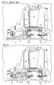
- FIG. 2 is an enlarged fragmentary cross-sectional view of the high pressure turbine showing a prior art orifice for turbine case cooling. Arrows in the figure show schematically the flow of the cooling air through the orifice.
- FIG. 3 is an enlarged fragmentary cross-sectional view similar to FIG. 2 of the high pressure turbine showing the erosion reduction apparatus of the present invention. Arrows in the figure show schematically the flow of the cooling air through the present invention.
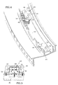
- FIG. 4 is an exploded isometric view of a portion of the first vane support in the high pressure turbine including the erosion reduction apparatus of the present invention.
- FIG. 5 is a cross-sectional view of the erosion reduction apparatus of the present invention taken along the lines 5-5 of FIG. 3 . Arrows in the figure show schematically the flow of the airstream in the apparatus.
- an axial flow, turbofan gas turbine engine 10 comprises generally a fan section 12 , a compressor section 14 , a combustor section 16 and a turbine section 18 disposed along axis A e and operates in accordance with principles well known in the art.
- the turbine section is comprised of a rotor assembly 22 and a stator assembly 24 .
- a plurality of rotor blades as represented by the single blade 26 , extend radially outwardly toward the stator assembly.
- An outer air seal 28 which is affixed to the turbine case 30 radially opposes the blades 26 and forms in part an annular chamber 32 between the seal 28 and the case 30 .
- the seal 28 keeps the gas flow in a primary flow path 38 between the turbine stator and rotor.
- a first row of stator vanes, as represented by the single vane 34 is affixed to the case upstream of the outer air seal.
- the stator vanes align the flow of the working medium gases while the rotor blades collect the energy of the working medium gases and turn the turbine which in turn drives the compressor.
- the first vane is supported radially inwardly by the first vane support 40 .
- the first vane support is annular in shape (see FIG. 4 ) and includes a plurality of metering orifices 42 spaced linearly therealong.
- a second row of stator vanes, as represented by the single vane 36 is affixed to the case downstream of the outer air seal.
- the working medium gases flow alternately through the rows of vanes and blades of the turbine section.
- Cooling air containing erosive particulates (such as sand) is bled from the high pressure compressor to the first vane cavity 41 .
- the cooling air having entrained particulates is usually metered through the orifices 42 .
- Higher cooling air pressure inherent in the first vane cavity 41 causes air to flow from the cavity 41 through the orifices 42 .
- the velocity of the cooling air and the particulates contained in the air is accelerated as the air flows through the orifices 42 due to the reduced flow area of the orifices as compared to the flow area of the annular chamber 32 . If this high velocity stream impinges on a structure, such as the turbine case, erosion of the structure is likely to take place.
- Erosion of the structure depends on several conditions such as the number and type of impinging particulates, particulate size, impact angles of the particulates, temperature and velocity of particulates. With other conditions being constant, this erosion is proportional to the velocity of the cooling airstream containing particulates.
- FIG. 3 a cross-sectional view of a turbine section including an erosion energy dissipater 44 embodying the present invention is shown attached to the inner diameter 50 of the annular first vane support 44 (also shown in FIG. 4 ).
- the dissipater 44 includes a plurality of inlet orifices 46 and a large diameter outlet orifice 48 .
- the erosion energy dissipater 44 has a first closed end 52 and a second open end 54 radially inward of the first end. The first and second end are separated by a sidewall structure 56 .
- the dissipater apparatus 44 has a flange 58 adjacent the second open end by which it is secured or riveted to the first vane support.
- cooling air from the high pressure compressor flows around the burner and into the first vane cavity 41 .
- This cooling air has particulates entrained in it. These particulates are present in the working medium flow path as they are ingested from the environment by the engine. The majority of the particulates are very fine in terms of size, thus they are carried through the different sections of the engine as the working medium gases flow axially downstream.
- cooling air Once cooling air enters the first vane cavity 41 , it is usually metered through the inlet orifices 46 of the erosion energy dissipater 44 .
- the inlet orifices are of equal size but oppose each other in location; therefore they cause airflow through them to be oppositely directed. Cooling airflow and erosive particulates travel through the inlet orifices at high speed. The opposing airstreams, shown in FIG. 5 , impact and cancel each other's energy. The cooling airflow and erosive particulates then exit the erosion energy dissipater through the large diameter outlet orifice 48 which slows down the flow to further reduce erosion.
- the area ratio defined as the ratio of the combined area of outlet orifice to that of the area of the inlet orifices is about at least 4.0. In the preferred embodiment, due to engine geometry constraints, the area ratio is 4.7. However, this ratio will depend on and be determined by structural and thermodynamic operating characteristics of engines in which the apparatus will be used. As the cooling airflow and particulates exit the outlet orifice of the dissipater, they impact the solid surface of the turbine case. The erosion of the turbine case is reduced significantly as the energy of the particulates has been dissipated prior to impacting with the turbine case.
- the primary advantage of the described embodiment is the enhanced durability and longevity of the turbine case.
- the present invention reduces erosion and thus reduces the wear of the turbine cases. This results in fewer repairs and overhauls of turbine cases and associated structure.
- Turbine first vane supports of the prior art can be refurbished in a cost effective manner to include the erosion energy dissipaters which results in reduced erosion of the turbine cases.
Landscapes
- Engineering & Computer Science (AREA)
- Chemical & Material Sciences (AREA)
- Combustion & Propulsion (AREA)
- Mechanical Engineering (AREA)
- General Engineering & Computer Science (AREA)
- Turbine Rotor Nozzle Sealing (AREA)
Applications Claiming Priority (2)
| Application Number | Priority Date | Filing Date | Title |
|---|---|---|---|
| US928149 | 1997-09-12 | ||
| US08/928,149 US6019575A (en) | 1997-09-12 | 1997-09-12 | Erosion energy dissipater |
Publications (3)
| Publication Number | Publication Date |
|---|---|
| EP0902166A2 true EP0902166A2 (de) | 1999-03-17 |
| EP0902166A3 EP0902166A3 (de) | 2000-07-05 |
| EP0902166B1 EP0902166B1 (de) | 2004-12-01 |
Family
ID=25455801
Family Applications (1)
| Application Number | Title | Priority Date | Filing Date |
|---|---|---|---|
| EP98307380A Expired - Lifetime EP0902166B1 (de) | 1997-09-12 | 1998-09-11 | Erosionsschutzschild in einer Luftströmung |
Country Status (4)
| Country | Link |
|---|---|
| US (1) | US6019575A (de) |
| EP (1) | EP0902166B1 (de) |
| JP (1) | JP4128670B2 (de) |
| DE (1) | DE69827887T2 (de) |
Cited By (3)
| Publication number | Priority date | Publication date | Assignee | Title |
|---|---|---|---|---|
| EP1818512A3 (de) * | 2006-02-09 | 2010-09-08 | United Technologies Corporation | Teilchensammler für einen Gasturbinenmotor |
| EP3409908A1 (de) * | 2017-05-30 | 2018-12-05 | United Technologies Corporation | Messlochanordung im turbinenteil eines gasturbinenmotors, turbine und gasturbinenmotor |
| EP3453964A1 (de) * | 2017-09-06 | 2019-03-13 | United Technologies Corporation | Schmutzfängersystem |
Families Citing this family (6)
| Publication number | Priority date | Publication date | Assignee | Title |
|---|---|---|---|---|
| US6413044B1 (en) * | 2000-06-30 | 2002-07-02 | Alstom Power N.V. | Blade cooling in gas turbine |
| US9737933B2 (en) | 2012-09-28 | 2017-08-22 | General Electric Company | Process of fabricating a shield and process of preparing a component |
| US10428676B2 (en) * | 2017-06-13 | 2019-10-01 | Rolls-Royce Corporation | Tip clearance control with variable speed blower |
| US10427075B2 (en) | 2017-06-20 | 2019-10-01 | United Technologies Corporation | Debris strainer for gas turbine engine cooling flow |
| US10584613B2 (en) * | 2018-07-18 | 2020-03-10 | United Technologies Corporation | Necked debris separator for a gas turbine engine |
| US11262077B2 (en) | 2019-09-20 | 2022-03-01 | Raytheon Technologies Corporation | Spall plate for consumable combustor support structures |
Citations (1)
| Publication number | Priority date | Publication date | Assignee | Title |
|---|---|---|---|---|
| US4053254A (en) | 1976-03-26 | 1977-10-11 | United Technologies Corporation | Turbine case cooling system |
Family Cites Families (15)
| Publication number | Priority date | Publication date | Assignee | Title |
|---|---|---|---|---|
| US2553562A (en) * | 1947-06-20 | 1951-05-22 | Houdry Process Corp | Atomizer with impinging streams |
| BE522350A (de) * | 1952-09-23 | |||
| US3675855A (en) * | 1971-04-12 | 1972-07-11 | Quaker Oats Co | Spray discharge nozzle |
| JPS51145064A (en) * | 1975-06-09 | 1976-12-13 | Tetsuaki Koga | Method of purification of a dust- containing gas and its enforcement d evice |
| US4155681A (en) * | 1977-02-14 | 1979-05-22 | General Electric Company | Manifold protection system |
| US4266951A (en) * | 1978-05-15 | 1981-05-12 | Air Pollution Technology, Inc. | Particle scrubber and related method |
| US4356009A (en) * | 1981-06-24 | 1982-10-26 | Air Pollution Technology, Inc. | Gas scrubber and related method |
| US4672886A (en) * | 1985-05-24 | 1987-06-16 | Bowles Fluidics Corporation | Oscillating air stream apparatus for automobile defroster |
| DE3615226A1 (de) * | 1986-05-06 | 1987-11-12 | Mtu Muenchen Gmbh | Heissgasueberhitzungsschutzeinrichtung fuer gasturbinentriebwerke |
| US4687495A (en) * | 1986-10-06 | 1987-08-18 | Imo Delaval Inc. | Flow control system for erosive fluids |
| US5359620A (en) * | 1992-11-12 | 1994-10-25 | Cymer Laser Technologies | Apparatus for, and method of, maintaining a clean window in a laser |
| US5523063A (en) * | 1992-12-02 | 1996-06-04 | Applied Materials, Inc. | Apparatus for the turbulent mixing of gases |
| US5271712A (en) * | 1993-01-06 | 1993-12-21 | Brandon Ronald E | Turbine geometry to reduce damage from hard particles |
| US5439347A (en) * | 1994-08-31 | 1995-08-08 | Brandon; Ronald E. | Turbine tip seal damage protection means |
| US5662292A (en) * | 1995-05-03 | 1997-09-02 | Greene; Andrew T. | Helicopter engine filter system |
-
1997
- 1997-09-12 US US08/928,149 patent/US6019575A/en not_active Expired - Lifetime
-
1998
- 1998-09-11 DE DE69827887T patent/DE69827887T2/de not_active Expired - Lifetime
- 1998-09-11 EP EP98307380A patent/EP0902166B1/de not_active Expired - Lifetime
- 1998-09-14 JP JP26000098A patent/JP4128670B2/ja not_active Expired - Fee Related
Patent Citations (1)
| Publication number | Priority date | Publication date | Assignee | Title |
|---|---|---|---|---|
| US4053254A (en) | 1976-03-26 | 1977-10-11 | United Technologies Corporation | Turbine case cooling system |
Cited By (4)
| Publication number | Priority date | Publication date | Assignee | Title |
|---|---|---|---|---|
| EP1818512A3 (de) * | 2006-02-09 | 2010-09-08 | United Technologies Corporation | Teilchensammler für einen Gasturbinenmotor |
| EP3409908A1 (de) * | 2017-05-30 | 2018-12-05 | United Technologies Corporation | Messlochanordung im turbinenteil eines gasturbinenmotors, turbine und gasturbinenmotor |
| EP3453964A1 (de) * | 2017-09-06 | 2019-03-13 | United Technologies Corporation | Schmutzfängersystem |
| US11187413B2 (en) | 2017-09-06 | 2021-11-30 | Raytheon Technologies Corporation | Dirt collector system |
Also Published As
| Publication number | Publication date |
|---|---|
| DE69827887D1 (de) | 2005-01-05 |
| EP0902166A3 (de) | 2000-07-05 |
| JP4128670B2 (ja) | 2008-07-30 |
| EP0902166B1 (de) | 2004-12-01 |
| JPH11141353A (ja) | 1999-05-25 |
| US6019575A (en) | 2000-02-01 |
| DE69827887T2 (de) | 2005-04-07 |
Similar Documents
| Publication | Publication Date | Title |
|---|---|---|
| EP1185765B1 (de) | Vorrichtung zur reduzierung der kühlung für einen turbineneinlasskanal | |
| EP1793086B1 (de) | Gasturbinenschaufel mit einem Partikeldeflektor | |
| US5215435A (en) | Angled cooling air bypass slots in honeycomb seals | |
| US6609884B2 (en) | Cooling of gas turbine engine aerofoils | |
| EP1106787B1 (de) | Kühlung eines Turbinenleitapparat-Segments | |
| EP1182339B1 (de) | Kühlung von Turbinenschaufeln durch spezifische Schaufelverteilung | |
| US3533712A (en) | Cooled vane structure for high temperature turbines | |
| EP0371207B1 (de) | Radiales Turbinenrad | |
| EP3597875B1 (de) | Partikelabscheider für einen gasturbinentriebwerk und entsprechendes installationsverfahren | |
| EP3081764A1 (de) | Variable beschichtungsporosität zur beeinflussung der umhüllung und der rotorhaltbarkeit | |
| KR20100080427A (ko) | 터빈 엔진용 인듀서와 관련된 방법, 시스템 및/또는 장치 | |
| CN107084004A (zh) | 用于涡轮发动机部件的冲击孔 | |
| US20100068069A1 (en) | Turbine Blade | |
| EP2947280B1 (de) | Turbinendüsen und kühlsysteme zum kühlen von gleitgelenken darin | |
| KR20240016880A (ko) | 충돌 냉각 통로를 갖는 터보기계 에어포일 | |
| EP0902166B1 (de) | Erosionsschutzschild in einer Luftströmung | |
| EP3557001B1 (de) | Kühlanordnung für motorkomponenten | |
| WO1990004089A1 (en) | Augmented turbine combustor cooling | |
| EP3453970A2 (de) | Schwimmerwandbrennkammerplatten mit Erhöhung der Wärmeübertragung | |
| EP2881542B1 (de) | Zweifach gegossene Turbinenleitschaufeln und Verfahren zur Kühlung der Gleitgelenke darin | |
| CA2680410C (en) | Turbine nozzle for a gas turbine engine |
Legal Events
| Date | Code | Title | Description |
|---|---|---|---|
| PUAI | Public reference made under article 153(3) epc to a published international application that has entered the european phase |
Free format text: ORIGINAL CODE: 0009012 |
|
| AK | Designated contracting states |
Kind code of ref document: A2 Designated state(s): DE FR GB |
|
| AX | Request for extension of the european patent |
Free format text: AL;LT;LV;MK;RO;SI |
|
| PUAL | Search report despatched |
Free format text: ORIGINAL CODE: 0009013 |
|
| AK | Designated contracting states |
Kind code of ref document: A3 Designated state(s): AT BE CH CY DE DK ES FI FR GB GR IE IT LI LU MC NL PT SE |
|
| AX | Request for extension of the european patent |
Free format text: AL;LT;LV;MK;RO;SI |
|
| RIC1 | Information provided on ipc code assigned before grant |
Free format text: 7F 01D 5/28 A, 7F 02C 7/30 B, 7F 01D 25/00 B |
|
| 17P | Request for examination filed |
Effective date: 20000925 |
|
| AKX | Designation fees paid |
Free format text: DE FR GB |
|
| 17Q | First examination report despatched |
Effective date: 20020529 |
|
| GRAP | Despatch of communication of intention to grant a patent |
Free format text: ORIGINAL CODE: EPIDOSNIGR1 |
|
| GRAS | Grant fee paid |
Free format text: ORIGINAL CODE: EPIDOSNIGR3 |
|
| GRAA | (expected) grant |
Free format text: ORIGINAL CODE: 0009210 |
|
| AK | Designated contracting states |
Kind code of ref document: B1 Designated state(s): DE FR GB |
|
| REG | Reference to a national code |
Ref country code: GB Ref legal event code: FG4D |
|
| REF | Corresponds to: |
Ref document number: 69827887 Country of ref document: DE Date of ref document: 20050105 Kind code of ref document: P |
|
| ET | Fr: translation filed | ||
| PLBE | No opposition filed within time limit |
Free format text: ORIGINAL CODE: 0009261 |
|
| STAA | Information on the status of an ep patent application or granted ep patent |
Free format text: STATUS: NO OPPOSITION FILED WITHIN TIME LIMIT |
|
| 26N | No opposition filed |
Effective date: 20050902 |
|
| REG | Reference to a national code |
Ref country code: FR Ref legal event code: PLFP Year of fee payment: 18 |
|
| PGFP | Annual fee paid to national office [announced via postgrant information from national office to epo] |
Ref country code: DE Payment date: 20150820 Year of fee payment: 18 Ref country code: GB Payment date: 20150825 Year of fee payment: 18 |
|
| PGFP | Annual fee paid to national office [announced via postgrant information from national office to epo] |
Ref country code: FR Payment date: 20150824 Year of fee payment: 18 |
|
| REG | Reference to a national code |
Ref country code: DE Ref legal event code: R119 Ref document number: 69827887 Country of ref document: DE |
|
| GBPC | Gb: european patent ceased through non-payment of renewal fee |
Effective date: 20160911 |
|
| REG | Reference to a national code |
Ref country code: FR Ref legal event code: ST Effective date: 20170531 |
|
| PG25 | Lapsed in a contracting state [announced via postgrant information from national office to epo] |
Ref country code: FR Free format text: LAPSE BECAUSE OF NON-PAYMENT OF DUE FEES Effective date: 20160930 Ref country code: DE Free format text: LAPSE BECAUSE OF NON-PAYMENT OF DUE FEES Effective date: 20170401 Ref country code: GB Free format text: LAPSE BECAUSE OF NON-PAYMENT OF DUE FEES Effective date: 20160911 |