EP0902100A1 - Thermospray method and apparatus for carrier body - Google Patents
Thermospray method and apparatus for carrier body Download PDFInfo
- Publication number
- EP0902100A1 EP0902100A1 EP98111596A EP98111596A EP0902100A1 EP 0902100 A1 EP0902100 A1 EP 0902100A1 EP 98111596 A EP98111596 A EP 98111596A EP 98111596 A EP98111596 A EP 98111596A EP 0902100 A1 EP0902100 A1 EP 0902100A1
- Authority
- EP
- European Patent Office
- Prior art keywords
- base body
- sprayed
- support cylinder
- pull
- disc
- Prior art date
- Legal status (The legal status is an assumption and is not a legal conclusion. Google has not performed a legal analysis and makes no representation as to the accuracy of the status listed.)
- Granted
Links
Images


Classifications
-
- C—CHEMISTRY; METALLURGY
- C23—COATING METALLIC MATERIAL; COATING MATERIAL WITH METALLIC MATERIAL; CHEMICAL SURFACE TREATMENT; DIFFUSION TREATMENT OF METALLIC MATERIAL; COATING BY VACUUM EVAPORATION, BY SPUTTERING, BY ION IMPLANTATION OR BY CHEMICAL VAPOUR DEPOSITION, IN GENERAL; INHIBITING CORROSION OF METALLIC MATERIAL OR INCRUSTATION IN GENERAL
- C23C—COATING METALLIC MATERIAL; COATING MATERIAL WITH METALLIC MATERIAL; SURFACE TREATMENT OF METALLIC MATERIAL BY DIFFUSION INTO THE SURFACE, BY CHEMICAL CONVERSION OR SUBSTITUTION; COATING BY VACUUM EVAPORATION, BY SPUTTERING, BY ION IMPLANTATION OR BY CHEMICAL VAPOUR DEPOSITION, IN GENERAL
- C23C4/00—Coating by spraying the coating material in the molten state, e.g. by flame, plasma or electric discharge
- C23C4/18—After-treatment
- C23C4/185—Separation of the coating from the substrate
Definitions
- the invention relates to a thermal spray process for the production of Carrier bodies and a device for performing the method, wherein the obtained carrier body used in particular in the graphics industry can be.
- DE 41 40 768 C2 discloses a method for producing an offset printing form a metallic material for a forme cylinder of a printing press.
- the plate-shaped blank is opened for printing plate production conventional type coated and exposed, after which the rectangular plate in a welding device by bending into a Bring hollow cylinder shape and clamped there in register.
- the one on top of the other facing edges of the plate are seam welded together longitudinally, whereby the welding process is carried out in such a way that a weld seam is formed which is on the top and Bottom each has a concave shape.
- the resulting printing form can be exposed to the plate-shaped blank coated and exposed on the forme cylinder.
- a disadvantage of this manufacturing process is the fact that the length is stretched of the plate-shaped blank, which will later give the diameter, exactly parallel and with a correspondingly high accuracy of significantly better than 1/10 mm tailored. It also causes the introduction of heat when welding a longitudinal distortion of the material in the weld area. This elongation leads to a ripple on both sides along the weld. When using a sleeve produced in this way leads to the inevitable waviness in the seam area to the fact that air pockets occur, which are under external pressure on the sleeve this migrate, which causes the sleeve to twist on the cylinder. This results in the need for an additional operation subsequent calibration of such sleeves made according to this procedure has been.
- DE 39 08 999 C2 discloses a cylinder body and a method for coating of the cylindrical body. It is proposed to have a cylindrical body like this to be provided with a seamless coating that as a coating material thixotropic multi-component material in the form of a propellant and inhibitor staggered, flowing foam with rotation and feed on the cylindrical body is applied approximately in a spiral.
- a coating material thixotropic multi-component material in the form of a propellant and inhibitor staggered, flowing foam with rotation and feed on the cylindrical body is applied approximately in a spiral.
- metallic aluminum or a carbon fiber reinforced plastic is used.
- plastic sleeves also has disadvantages. For example in view of the considerably lower modulus of elasticity, these have to be increased Wall thickness can be made to be comparable to metallic sleeves Achieve seat strength. High wall thicknesses, in turn, for example in the Application of functional layers of higher temperature to be treated are exposed to temperature, resulting in loss of Dimensional accuracy and build up high internal stresses.
- EP 0 421 145 A2 and EP 0 715 966 A1 are sleeve-shaped rubber blankets become known, which laterally on blanket cylinders from Have rotary printing presses installed.
- the rubber coating is on Nickel sleeves applied.
- the nickel sleeves are electroplated manufactured.
- a mother cylinder is inserted into the nickel bath a thin nickel skin, which later after reaching the required wall thickness is rolled from the master cylinder.
- the nickel sleeve production in this way has an increased power requirement and is extremely time consuming.
- Thermal spray processes are used today to make the most diverse Components such as machine components, implants or structural components to coat a variety of materials.
- the one with the coating Spraying methods and spray additives are used to a high degree application-specific.
- Classic areas of application of thermal Spraying is the wear and corrosion protection, the repair coating as well as thermal or electrical insulation and often a combination of these Aims.
- the metal or the metal alloy or the self-flowing alloy can be sprayed on in accordance with the flame spraying process.
- the arc spraying process can also be used, as can the high-speed flame spraying process.
- the material to be sprayed on can be an oxide or also carbides or ceramic-metal mixtures (cermets). In order to prepare the outer surface of the shaping base body for the thermal spray layer to be produced, this must be conditioned, for which purpose a blasting process is used.
- a roughness of the lateral surface is brought about, which is characterized in that the elevations determining the roughness have a round contour.
- the roughness of the outer surface of the shaping body is R Z 25 ⁇ m.
- the material preferably used to produce the rough outer surface in the blasting process to be used is glass spheres.
- the prevailing pressure in the blasting process for spraying the glass balls is between 2.5 and 3.5 bar.
- the conditioned outer surface of the shaping base body is provided with a layer of a release agent which is up to 5 ⁇ m thick.
- the release agent can be powdered graphite dust or silicone can also be used. It is also possible to use Teflon as a release agent.
- the inventive device for performing the thermal Spraying process comprises a shaping body, which is a support cylinder as well as a pull-off disc, between the support cylinder and the Pull-off round a deflection bevel is formed, which is a constriction in the thermal applied spray layer generated.
- a shaping body which is a support cylinder as well as a pull-off disc, between the support cylinder and the Pull-off round a deflection bevel is formed, which is a constriction in the thermal applied spray layer generated.
- An extraction chamber is provided, which is equipped with a Pressure medium through the pull-off disc or through the support cylinder is pressurizable.
- An annular gap between the support cylinder and The pull-off blank is made up of an end face of the support cylinder and the pull-off blank limited. The annular gap opens below the necking point of the thermal sprayed material in the area of the deflection chamfer.
- both the support cylinder on the front side and the pull-off disc are on the front side provided with a taper.
- Figure 1 is an arrangement for performing the reproduced method according to the invention.
- An order station 1 comprises one on a machine frame 2 in Recording tips 3 and 4 rotatably mounted base body, one Includes support cylinder 5 and a pull-off blank (see FIG. 2).
- the the is to be applied to the thermal spray coating which gives the shape of the base body the receiving tips 3 and 4 rotatably supported and can not by one here drive shown in detail can be set in rotation.
- the support cylinder 5 is by means of a cylinder pin 6 in the receiving tip 3, the The end face of the cylinder faces the receiving tip 3.
- the material to be sprayed on via a feed line 15 applies to the outer surface 8 of the base body.
- the spray layer very ductile and elastic is very similar to solid material.
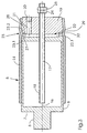
- FIG. 2 shows in longitudinal section one of a spray layer to be applied thermally the basic body.
- the shaping base body shown in longitudinal section comprises a Support cylinder 5, on the end face 7 of which the cylinder journal 6 is located.
- the Support cylinder 5 has a cavity, the end faces and Shell surfaces 8 limited and penetrated by a guide rod 17.
- To one annular end face 27 of the support cylinder 5 is a corresponding annular end face 28 of a pull-off disc 19.
- the Pull-off disc 19, also penetrated by the guide rod 17 already mentioned, which is provided with a profile 18 is with a connection 20 for a Media equipped.
- the connection 20 for the pressure medium comprises one Channel 21, which is in an expansion chamber 22 between the support cylinder 5 and the Pull-off disc 19 opens.
- the expansion chamber 22 is shown in FIG Idle state 22.1 shown.
- the through the mentioned end faces 27, 28 of Support cylinder 5 or pull-off disc 19 formed joint 29 forms an annular gap extending around the cylinder axis into a deflection chamfer 23 at the transition of the support cylinder 5 to the extraction disc 19 opens.
- Deflection chamfer 23.1 is provided as well as a deflection chamfer 23.2 on the condenser side is provided, which in the abutting state of the support cylinder 5 and Pulling disc 19 form a continuous deflection chamfer 23, which leads to the formation of a Constriction 30 leads in the thermal spray layer 14.
- the surface of the support cylinder 5 is conditioned by means of a blasting process.
- blasting processes are used to roughen subsurface surfaces with the aim of optimal adhesion. This means making the surface as sharp as possible.
- the spray layer 14 in order to ensure that the spray layer 14 can be easily removed, the roughness must be brought about with edges that are as round as possible.
- the surface of the support cylinder 5 is therefore produced using a blasting method using glass balls of a defined size and a blasting pressure between 2.5 and 3.5 bar.
- the average roughness depth R Z which is generated by this method, is R Z 25 ⁇ m.
- the jacket surface 8 conditioned in this way is provided with a release agent provided what is applied in a film up to 5 ⁇ m thick.
- a release agent such as graphite, silicone or Teflon, acts one mechanical clawing of the striking at high speed Spray particles against the base of the base body and prevents Baking together with the outer surface 8 of the support cylinder 5.
- the applied Release agent supports the detachment of the spray layer 14 after it has cooled the outer surface 8 of the base body.
- FIG. 3 shows a spray layer applied to the shaping base body shown with trained constriction 30.
- the expansion chamber 22 located between the support cylinder 5 and the pull-off disc 19 is in its idle state 22.1, ie not acted upon by a pressure medium.
- a constriction point 30 has formed in the spray layer 14.
- the outer surface of the removal disc 19 was not subjected to any surface conditioning, which is why its roughness is higher than that of the outer surface 8 of the support cylinder 5. This means that the part of the spray layer 14 which is applied to the pull-off disc 19 of the shaping base body opposes the detachment with a higher resistance.
- the expansion chamber 22, which is still in the idle state 22.1, is connected to the latter via the gap 29 defined by the contact area of the end face 27 or 28 of the support cylinder 5 or pull-off probe 19, which opens approximately centrally into the deflection chamfer 23.
- FIG. 4 shows a part that has been detached due to the expansion chamber being acted upon coherent thermal spray coating.
- the pull-off disc 19 is acted upon by a pressure medium, which via the Channel 21 acts on the expansion chamber 22.
- a pressure medium which via the Channel 21 acts on the expansion chamber 22.
- By building up Pressure in the expansion chamber 22 results in a surface pressure between the Support cylinder 5 and the pull-off disc 19, whereby the gap 29 between the End faces 27, 28 of the support cylinder 5 and pull-off 19 is widened.
- the gap 29 passes the pressure medium under the coherent sleeve-shaped Spray layer 14 and applied to the underside 14.2.
- the Deflection phase 23 In order to avoid a sudden impact on the spray layer 14 beginning formation of the gap 29 by the pressure medium is carried out by the Deflection phase 23 generates an additional length in the form of a constriction 30.
- the area covering the support cylinder 5 is the spray layer 14 detached from the outer surface 8 of the support cylinder 5 while the part of the spray layer 14, which is located on the peel 19, because of the greater friction still adheres to the outer surface of the extraction disc 19.
- Sleeves produced in this way without a seam have a ductile elastic Behavior on and are in the manner described above according to the invention can be produced considerably more cost-effectively than those known from the prior art elaborately deposited on a master cylinder Nickel sleeves.
- the material thicknesses of the tubular bodies to be produced are adjustable between 0.1 and 0.6mm depending on feed and speed of the shaping basic body, in relation to the material discharge on Spray head 11.
- Metal or sprayed metal alloys can be used, for example, for that Apply the necessary transfer layers using offset processes or pressers for Manufacture gravure applications. It is also used as a sleeve Printing form in printing machines possible to use instead of finite Printing plates.
Abstract
Description
Die Erfindung bezieht sich auf ein thermisches Spritzverfahren zur Herstellung von Trägerkörpern und eine Vorrichtung zur Durchführung des Verfahrens, wobei die erhaltenen Trägerkörper insbesondere in der graphischen Industrie verwendet werden können.The invention relates to a thermal spray process for the production of Carrier bodies and a device for performing the method, wherein the obtained carrier body used in particular in the graphics industry can be.
DE 41 40 768 C2 offenbart ein Verfahren zur Herstellung einer Offsetdruckform aus einem metallischen Werkstoff für einen Formzylinder einer Druckmaschine. Zunächst wird eine Platte auf das dem Umfang und der Breite des Formzylinders entsprechende Maß zugeschnitten und an mindestens einer Stirnseite mit Registereinrichtungen versehen. Anschließend wird der plattenförmige Zuschnitt auf für die Druckformherstellung herkömmliche Art beschichtet und belichtet, wonach die rechteckige Platte in einer Schweißvorrichtung durch Biegen in eine Hohlzylinderform gebracht und dort registerhaltig eingespannt wird. Die aufeinander zuweisenden Kanten der Platte werden miteinander längs nahtverschweißt, wobei der Schweißprozeß so geführt wird, daß eine Schweißnaht entsteht, die auf Ober- und Unterseite jeweils eine konkave Form aufweist. Neben der Beschichtung und Belichtung des plattenförmigen Zuschnittes kann die daraus entstehende Druckform auf dem Formzylinder beschichtet und belichtet werden.DE 41 40 768 C2 discloses a method for producing an offset printing form a metallic material for a forme cylinder of a printing press. First becomes a plate on the circumference and width of the forme cylinder cut to size and with at least one end face Provide register facilities. Then the plate-shaped blank is opened for printing plate production conventional type coated and exposed, after which the rectangular plate in a welding device by bending into a Bring hollow cylinder shape and clamped there in register. The one on top of the other facing edges of the plate are seam welded together longitudinally, whereby the welding process is carried out in such a way that a weld seam is formed which is on the top and Bottom each has a concave shape. In addition to the coating and The resulting printing form can be exposed to the plate-shaped blank coated and exposed on the forme cylinder.
Nachteilig bei diesem Herstellungsverfahren ist die Tatsache, die gestreckte Länge des plattenförmigen Zuschnittts, die später den Durchmesser ergeben soll, exakt parallel und mit entsprechend hoher Genauigkeit von deutlich besser als 1/10 mm zuzuschneiden. Weiterhin verursacht die Einleitung von Wärme beim Schweißen einen Längsverzug des Materials im Schweißnahtbereich. Diese Längung führt zu einer Welligkeit beidseitig längs der Schweißnaht. Bei der Benutzung einer solcherart hergestellten Hülse führt diese unvermeidbare Welligkeit im Nahtbereich dazu, daß sich Lufteinschlüsse einstellen, die bei äußerem Druck auf die Hülse unter dieser wandern, was eine Verdrehung der Hülse auf dem Zylinder zur Folge hat. Daraus ergibt sich die Notwendigkeit eines zusätzlichen Arbeitsganges zur nachträglichen Kalibrierung solcher Hülsen, die gemäß dieses Verfahrens hergestellt wurde.A disadvantage of this manufacturing process is the fact that the length is stretched of the plate-shaped blank, which will later give the diameter, exactly parallel and with a correspondingly high accuracy of significantly better than 1/10 mm tailored. It also causes the introduction of heat when welding a longitudinal distortion of the material in the weld area. This elongation leads to a ripple on both sides along the weld. When using a sleeve produced in this way leads to the inevitable waviness in the seam area to the fact that air pockets occur, which are under external pressure on the sleeve this migrate, which causes the sleeve to twist on the cylinder. This results in the need for an additional operation subsequent calibration of such sleeves made according to this procedure has been.
DE 39 08 999 C2 offenbart eine Zylinderkörper und ein Verfahren zur Beschichtung des zylindrischen Körpers. Es wird vorgeschlagen, einen zylindrischen Körper derart mit einer nahtlosen Beschichtung zu versehen, daß als Beschichtungsmaterial ein thixotropes Mehrkomponentenmaterial in Form eines mit Treibmitteln und Inhibitoren versetzten, fließförmigen Schaumes unter Drehung und Vorschub auf dem zylindrischen Körper etwa spiralförmig aufgetragen wird. Als Hülsenmaterial wird metallisches Aluminium oder ein kohlefaserverstärkter Kunststoff verwendet. Die Verwendung von Kunststoffhülsen hat allerdings auch Nachteile. Beispielsweise müssen diese angesichts des erheblich geringeren Elastizitätsmoduls mit höherer Wandstärke gefertigt werden, um mit metallischen Hülsen vergleichbare Sitzfestigkeiten zu erzielen. Hohe Wandstärken wiederum, die beispielsweise bei der Aufbringung von wärme zu behandelnden Funktionsschichten höherer Temperatur ausgesetzt werden, sind temperaturempfindlich, was zum Verlust der Maßgenauigkeit und zum Aufbau hoher innerer Spannungen führen kann.DE 39 08 999 C2 discloses a cylinder body and a method for coating of the cylindrical body. It is proposed to have a cylindrical body like this to be provided with a seamless coating that as a coating material thixotropic multi-component material in the form of a propellant and inhibitor staggered, flowing foam with rotation and feed on the cylindrical body is applied approximately in a spiral. As a sleeve material metallic aluminum or a carbon fiber reinforced plastic is used. The However, the use of plastic sleeves also has disadvantages. For example in view of the considerably lower modulus of elasticity, these have to be increased Wall thickness can be made to be comparable to metallic sleeves Achieve seat strength. High wall thicknesses, in turn, for example in the Application of functional layers of higher temperature to be treated are exposed to temperature, resulting in loss of Dimensional accuracy and build up high internal stresses.
Aus EP 0 421 145 A2 sowie EP 0 715 966 A1 sind hülsenförmige Gummitücher bekannt geworden, die sich seitlich auf Gummituchzylinder von Rotationsdruckmaschinen aufbringen lassen. Die Gummibeschichtung ist auf Nickelhülsen aufgebracht. Die Nickelhülsen werden auf galvanischem Wege hergestellt. An einem in das Nickelbad eingelassenen Mutterzylinder scheidet sich eine dünne Nickelhaut ab, die später nach Erreichen der erforderlichen Wandstärke vom Mutterzylinder abgewalkt wird. Die Nickelhülsenherstellung auf diesem Wege hat einen erhöhten Strombedarf zur Folge und ist außerordentlich zeitaufwendig. From EP 0 421 145 A2 and EP 0 715 966 A1 are sleeve-shaped rubber blankets become known, which laterally on blanket cylinders from Have rotary printing presses installed. The rubber coating is on Nickel sleeves applied. The nickel sleeves are electroplated manufactured. A mother cylinder is inserted into the nickel bath a thin nickel skin, which later after reaching the required wall thickness is rolled from the master cylinder. The nickel sleeve production in this way has an increased power requirement and is extremely time consuming.
Thermische Spritzverfahren werden heute eingesetzt, um die unterschiedlichsten Bauteile wie Maschinenkomponenten, Implantate oder Bauwerkkomponenten mit einer Vielzahl von Werkstoffen zu beschichten. Die bei der Beschichtung eingesetzten Spritzverfahren und Spritzzusatzwerkstoffe sind in hohem Maße anwendungsfallspezifisch. Klassische Anwendungsgebiete des thermischen Spritzens sind der Verschleiß und der Korrosionsschutz, die Reparaturbeschichtung sowie thermische oder elektrische Isolation und häufig auch eine Kombination dieser Ziele.Thermal spray processes are used today to make the most diverse Components such as machine components, implants or structural components to coat a variety of materials. The one with the coating Spraying methods and spray additives are used to a high degree application-specific. Classic areas of application of thermal Spraying is the wear and corrosion protection, the repair coating as well as thermal or electrical insulation and often a combination of these Aims.
Ziel der erwähnten konventionellen Spritztechnik zur Lösung anspruchsvoller Beschichtungsaufgaben ist es bisher gewesen, eine möglichst gute Haftung der erzeugten Schicht auf dem zu beschichtenden Bauteil zu erhalten.Aim of the conventional spraying technique mentioned to solve more demanding Coating tasks have so far been to ensure the best possible adhesion of the to obtain the generated layer on the component to be coated.
Ausgehend von den Schwächen und Nachteilen des aufgezeigten Standes der Technik und in Weiterentwicklung der Anwendung von Spritzverfahren liegt der vorliegenden Erfindung die Aufgabe zugrunde, der graphischen Industrie steifigkeits- und festigkeitsoptimierte Basisträgerhülsen zur Herstellung von Übertragungsträgern, Druckformen, Presseuren und dergleichen preiswert zur Verfügung zu stellen.Based on the weaknesses and disadvantages of the status of the The technology and further development of the application of spray processes lies in the present invention the object of the graphic industry stiffness and strength-optimized base carrier sleeves for the production of Transfer carriers, printing forms, impression rollers and the like inexpensive for To make available.
Die Aufgabe wird erfindungsgemäß durch die Merkmale des Patentanspruchs 1 gelöst.The object is achieved by the features of claim 1 solved.
Die sich aus der erfindungsgemäßen Lösung ergebenden Vorteile sind vielfältiger Natur. Im Gegensatz zu den bisher mittels thermischer Spritzverfahren erzeugten Schichten, sind die gemäß des erfindungsgemäßen Verfahrens hergestellten Schichten von dem hier lediglich formgebenden Körper einfach abzulösen. Die sich während des Spritzverfahrens ergebende duktile, elastische Schicht ist solidem Material sehr ähnlich und verleiht dem so gewonnenen Körper eine Elastizität, die dessen einfache Handhabung ermöglicht. Die Duktilität des Körpers erlaubt ein Aufweiten des Körpers zum Aufziehen auf einen Zylinder einer graphischen Maschine; nach Abschaltung eines zum Weiten des duktilen Körpers erforderlichen unter Druck stehenden Mediums kann der Körper mittels Preßsitz auf dem Umfang eines Zylinders gehalten werden. Dabei kann es sich sowohl um einen Übertragungszylinder als auch einen Druckformzylinder handeln, auf welchem der erfindungsgemäß hergestellte hülsenförmige Körper aufziehbar ist. Neben Applikation für das Offsetverfahren sind auch die Anwendung der erfindungsgemäß erhaltenden hülsenförmigen Körper im Tiefdruckverfahren denkbar.The advantages resulting from the solution according to the invention are more diverse Nature. In contrast to those previously produced using thermal spraying processes Layers are those produced according to the method of the invention Easy to remove layers from the body that only gives shape. Which ductile, elastic layer resulting from the spraying process is solid Material very similar and gives the body thus obtained an elasticity that its easy handling enables. The ductility of the body allows one Expanding the body for mounting on a cylinder of a graphic Machine; after switching off one necessary to expand the ductile body The body can be pressurized on the circumference using a press fit be held by a cylinder. It can be both Actuate transfer cylinder as well as a printing form cylinder on which the sleeve-shaped body produced according to the invention can be drawn up. Next Applications for the offset method are also the application of the invention preserving sleeve-shaped body in the gravure process conceivable.
In weiterer Ausgestaltung des der Erfindung zugrunde liegenden Gedankens kann das Aufspritzen des Metalls oder der Metallegierung oder der selbstfließenden Legierung gemäß des Flammspritzverfahrens erfolgen. Neben dem Flammspritzverfahren kann auch das Lichtbogenspritzverfahren angewendet werden, sowie auch das Hochgeschwindigkeits-Flammspritzverfahren Verwendung finden. Neben Metallen oder Metallegierungen oder einer selbstfließenden Legierung kann das aufzuspritzende Material ein Oxid sein oder auch Karbide oder auch Keramik-Metall-Mischungen (Cermets). Zur Vorbereitung der Mantelfläche des formgebenden Grundkörpers für die herzustellende thermische Spritzschicht muß diese konditioniert werden, wozu ein Strahlverfahren Verwendung findet. Mittels des Strahlverfahrens wird eine Rauheit der Mantelfläche herbeigeführt, die sich dadurch auszeichnet, daß die die Rauheit bestimmenden Erhebungen eine runde Kontur aufweisen. Die Rauheit der Mantelfläche des formgebenden Körpers beträgt RZ 25µm. Das zur Erzeugung der rauhen Mantelfläche vorzugsweise verwendete Material beim dem zu verwendenden Strahlverfahren sind Glaskugeln. Der beim Strahlverfahren vorherrschende Druck für das Aufspritzen der Glaskugeln liegt zwischen 2,5 und 3,5 bar. Um die Ablösung der erfindungsgemäß hergestellten thermischen Spritzschicht von der Mantelfläche des formgebenden Grundkörpers zu erleichtern, wird die konditionierte Mantelfläche des formgebenden Grundkörpers mit einer bis zu 5µm dicken Schicht eines Trennmittels versehen. Bei dem Trennmittel kann es sich um pulverförmigen Graphitstaub handeln oder es kann auch Silikon verwendet werden. Ferner ist als Trennmittel die Verwendung von Teflon möglich. Nach dem die Mantelfläche des formgebenden Grundkörpers solcherart vorbehandelt worden ist, wird die thermisch aufzutragende Spritzschicht in Bereich zwischen 0,1 und 0,6mm Dicke aufgetragen.In a further embodiment of the idea on which the invention is based, the metal or the metal alloy or the self-flowing alloy can be sprayed on in accordance with the flame spraying process. In addition to the flame spraying process, the arc spraying process can also be used, as can the high-speed flame spraying process. In addition to metals or metal alloys or a self-flowing alloy, the material to be sprayed on can be an oxide or also carbides or ceramic-metal mixtures (cermets). In order to prepare the outer surface of the shaping base body for the thermal spray layer to be produced, this must be conditioned, for which purpose a blasting process is used. By means of the blasting method, a roughness of the lateral surface is brought about, which is characterized in that the elevations determining the roughness have a round contour. The roughness of the outer surface of the shaping body is R Z 25 µm. The material preferably used to produce the rough outer surface in the blasting process to be used is glass spheres. The prevailing pressure in the blasting process for spraying the glass balls is between 2.5 and 3.5 bar. In order to facilitate the detachment of the thermal spray layer produced according to the invention from the outer surface of the shaping base body, the conditioned outer surface of the shaping base body is provided with a layer of a release agent which is up to 5 μm thick. The release agent can be powdered graphite dust or silicone can also be used. It is also possible to use Teflon as a release agent. After the outer surface of the shaping base body has been pretreated in this way, the spray layer to be applied thermally is applied in a range between 0.1 and 0.6 mm thick.
Die erfindungsgemäße Vorrichtung zur Durchführung des thermischen Spritzverfahrens umfaßt einen formgebenden Grundkörper, der einen Stützzylinder sowie eine Abziehronde umfaßt, wobei zwischen dem Stützzylinder und der Abziehronde eine Auslenkfase gebildet ist, die eine Einschnürstelle in der thermisch aufgebrachten Spritzschicht erzeugt. Zwischen dem Stützzylinder und der Abziehronde ist eine Expansionskammer vorgesehen, welche mit einem Druckmedium durch die Abziehronde oder auch durch den Stützzylinder druckbeaufschlagbar ist. Ein ringförmiger Spalt zwischen Stützzylinder und Abziehronde wird von je einer Stirnfläche des Stützzylinders und der Abziehronde begrenzt. Der ringförmige Spalt mündet unterhalb der Einschnürstelle des thermisch gespritzten Materials in den Bereich der Auslenkfase.The inventive device for performing the thermal Spraying process comprises a shaping body, which is a support cylinder as well as a pull-off disc, between the support cylinder and the Pull-off round a deflection bevel is formed, which is a constriction in the thermal applied spray layer generated. Between the support cylinder and the An extraction chamber is provided, which is equipped with a Pressure medium through the pull-off disc or through the support cylinder is pressurizable. An annular gap between the support cylinder and The pull-off blank is made up of an end face of the support cylinder and the pull-off blank limited. The annular gap opens below the necking point of the thermal sprayed material in the area of the deflection chamfer.
Zur Verbesserung der Ausbildung eines Luftspaltes und um ein leichteres Ablösen der thermisch gespritzten Schicht von der Mantelfläche des Stützzylinders zu erzielen, sind sowohl der Stützzylinder stirnseitig als auch die Abziehronde stirnseitig mit einer Verjüngung versehen.To improve the formation of an air gap and to make it easier to detach the thermally sprayed layer from the outer surface of the support cylinder achieve, both the support cylinder on the front side and the pull-off disc are on the front side provided with a taper.
Weitere Details des erfindungsgemäßen Verfahrens und der erfindungsgemäßen Vorrichtung können der Beschreibung und den beigefügten Figuren entnommen werden.Further details of the inventive method and the inventive Device can be found in the description and the attached figures become.
Es zeigt:
- Figur 1
- den schematisch dargestellten Aufbau einer Anlage zum thermischen Aufbringen einer Spritzschicht auf einen formgebenden Grundkörper,
Figur 2- einen Längsschnitt durch den formgebenden Grundkörper, bestehend aus Stützzylinder und Abziehronde,
Figur 3- eine auf dem formgebenden Grundkörper aufgebracht Spritzschicht mit ausgebildeter Einschnürstelle, jedoch noch nicht beaufschlagter Expansionskammer und
Figur 4- eine durch Beaufschlagung der Expansionskammer teilweise abgelöste thermische Spritzschicht.
- Figure 1
- the schematically illustrated structure of a system for the thermal application of a spray layer on a shaping base body,
- Figure 2
- a longitudinal section through the shaping base body, consisting of a support cylinder and pull-off disc,
- Figure 3
- a spray layer applied to the shaping base body with a trained constriction point but not yet loaded expansion chamber and
- Figure 4
- a thermal spray layer partially detached by loading the expansion chamber.
In Figur 1 ist in schematischer Darstellung eine Anordnung zur Durchführung des erfindungsgemäßen Verfahrens wiedergegeben.In Figure 1 is an arrangement for performing the reproduced method according to the invention.
Eine Auftragsstation 1 umfaßt einen an einem Maschinengestell 2 in
Aufnahmespitzen 3 bzw. 4 drehbar gelagerten Grundkörper, der einen
Stützzylinder 5 sowie eine Abziehronde umfaßt (vergl. Figur 2). Der der
aufzubringenden thermischen Spritzschicht die Form verleihende Grundkörper ist in
den Aufnahmespitzen 3 und 4 drehbar gelagert und kann durch einen hier nicht
näher dargestellten Antrieb in Rotation versetzt werden. Der Stützzylinder 5 ist
mittels eines Zylinderzapfens 6 in der Aufnahmespitze 3 aufgenommen, die
Zylinderstirnseite ist der Aufnahmespitze 3 zugewandt. Parallel zur Achse des
Stützzylinders 5 ist ein Schlitten 9 angeordnet, der in Führungen 10 am
Maschinengestell in Vorschubrichtung 13 verfahrbar ist. Auf den Schlitten 9 ist ein
Spritzkopf 11 angeordnet, der über eine Zuleitung 15 das aufzuspritzende Material
auf die Mantelfläche 8 des Grundkörpers aufträgt. Je nach Vorschubgeschwindigkeit
und Drehzahl des formgebenden Grundkörpers lassen sich Spritzschichten 14 im
Dickenbereich zwischen 0,1 und 0,6mm herstellen, wobei die Spritzschicht sehr
duktil und elastisch ist mit großer Ähnlichkeit zu solidem Material. Solcherart
hergestellte endlose Hülsen aus zusammenhängendem Material lassen sich - wie
weiter unten noch detaillierter beschrieben werden wird - vom Umfang des
Stützzylinders 5 ablösen.An order station 1 comprises one on a
Figur 2 zeigt im Längsschnitt einen einer thermisch aufzubringenden Spritzschicht die Form verleihenden Grundkörper.FIG. 2 shows in longitudinal section one of a spray layer to be applied thermally the basic body.
Der im Längsschnitt dargestellte formgebende Grundkörper umfaßt einen
Stützzylinder 5, an dessen Stirnfläche 7 sich der Zylinderzapfen 6 befindet. Der
Stützzylinder 5 verfügt über einen Hohlraum, der von Stirnflächen und
Mantelflächen 8 begrenzt und von einer Führungsstange 17 durchsetzt wird. An eine
ringförmige verlaufende Stirnfläche 27 des Stützzylinders 5 liegt eine
korrespondierende ringförmige Stirnfläche 28 einer Abziehronde 19 an. Die
Abziehronde 19, ebenfalls durchsetzt von der bereits erwähnten Führungsstange 17,
welche mit einem Profil 18 versehen ist, ist mit einem Anschluß 20 für ein
Druckmedium ausgestattet. Der Anschluß 20 für das Druckmedium umfaßt einen
Kanal 21, der in einer Expansionskammer 22 zwischen dem Stützzylinder 5 und der
Abziehronde 19 mündet. Die Expansionskammer 22 ist in Figur 1 im
Ruhezustand 22.1 gezeigt. Die durch die erwähnten Stirnflächen 27, 28 von
Stützzylinder 5 bzw. Abziehronde 19 gebildete Fuge 29 bildet einen sich ringförmig
um die Zylinderachse erstreckenden Spalt, der in eine Auslenkfase 23 am Übergang
des Stützzylinders 5 zur Abziehronde 19 mündet. Sowohl zylinderseitig ist eine
Auslenkfase 23.1 vorgesehen wie auch rondenseitig eine Auslenkfase 23.2
vorgesehen ist, welche im aneinander liegenden Zustand von Stützzylinder 5 und
Abziehronde 19 eine kontinuierliche Auslenkfase 23 bilden, was zur Bildung einer
Einschnürstelle 30 in der thermischen Spritzschicht 14 führt.The shaping base body shown in longitudinal section comprises a
Der Vollständigkeit halber sei noch erwähnt, daß zur Wegbegrenzung der
Abziehronde 19 auf der Führungsstange 17 eine Mutter 24 samt Kontermutter 25 als
Anschlag vorgesehen sind, um bei Druckbeaufschlagung der Expansionskammer 22
mit einem Druckmedium den Verfahrweg der Abziehronde 19 relativ zum
Stützzylinder 5 zu begrenzen.For the sake of completeness, it should also be mentioned that the
Pulling
Im in Figur 2 gezeigten Zustand - vor Auftrag einer thermischen Spritzschicht - wird
die Oberfläche des Stützzylinders 5 mittels eines Strahlverfahrens konditioniert.
Üblicherweise werden mit Strahlverfahren Untergrundflächen aufgerauht, mit dem
Ziel optimaler Haftung. Dies bedeutet, die Oberfläche so scharfkantig rauh wie
irgend möglich zu erzeugen. Um jedoch eine leichte Ablösbarkeit der
Spritzschicht 14 zu gewährleisten, muß die Rauheit mit möglichst runden Kanten
herbeigeführt werden. Daher wird die Oberfläche des Stützzylinders 5 mit einem
Strahlverfahren unter Einsatz von Glaskugeln definierter Größe und einem
Strahldruck zwischen 2,5 und 3,5 bar erzeugt. Die mittlere Rauhtiefe RZ, die mittels
dieses Verfahrens erzeugt wird, beträgt RZ 25µm.In the state shown in FIG. 2 - before applying a thermal spray layer - the surface of the
Nach dem Anrauhen der Mantelfläche 8 des Stützzylinders 5 gemäß oben
Gesagtem, wird die solcherart konditionierte Mantelfläche 8 mit einem Trennmittel
versehen, was in einem Film bis zu 5µm Dicke aufgetragen wird. Die Applikation
eines Trennmittels, wie beispielsweise Graphit, Silikon oder Teflon, wirkt einer
mechanischen Verkrallung der mit hoher Geschwindigkeit auftreffenden
Spritzpartikel mit dem Untergrund des Grundkörpers entgegen und verhindert ein
Zusammenbacken mit der Mantelfläche 8 des Stützzylinders 5. Das aufgebrachte
Trennmittel unterstützt nach dem Erkalten der Spritzschicht 14 deren Ablösen von
der Mantelfläche 8 des Grundkörpers.After roughening the
In Figur 3 ist eine auf dem formgebenden Grundkörper aufgebrachte Spritzschicht
mit ausgebildeter Einschnürstelle 30 dargestellt.FIG. 3 shows a spray layer applied to the shaping base body
shown with trained
Auf die konditionierte - mit einer Rauhtiefe von RZ = 25µm und mit einem Trennmittel
versehene - Mantelfläche 8 des Stützzylinders 5 ist mit der Anordnung gemäß
Figur 3 unter Rotation des formgebenden Grundkörpers und Vorschub des
Spritzkörpers 11 die Spritzschicht 14 aufgetragen. Die zwischen Stützzylinder 5 und
Abziehronde 19 befindliche Expansionskammer 22 befindet sich in ihrem
Ruhezustand 22.1, d.h. nicht von einem Druckmedium beaufschlagt. Im Bereich der
durch die beiden Verjüngungsbereiche 23.1 und 23.2 am Stützzylinder 5 und
Abziehronde 19 gebildeten Auslenkfase 23 hat sich in der Spritzschicht 14 eine
Einschnürstelle 30 gebildet. Die Mantelfläche der Abziehronde 19 ist vor Aufbringen
der Spritzschicht 14 keiner Oberflächenkonditionierung unterzogen worden, weshalb
deren Rauheit höher als die der Mantelfläche 8 des Stützzylinders 5 ist. Dies
bedeutet, daß der Teil der Spritzschicht 14, der auf der Abziehronde 19 des
formgebenden Grundkörpers aufgebracht ist, der Ablösung einen höheren
Widerstand entgegensetzt. Die noch im Ruhezustand 22.1 befindliche
Expansionskammer 22 ist über den durch den Kontaktbereich der Stirnfläche 27
bzw. 28 von Stützzylinder 5 bzw. Abziehronde 19 definierten Spalt 29, der etwa
mittig in die Auslenkfase 23 mündet, mit dieser verbunden.The sprayed
Figur 4 zeigt eine durch Beaufschlagung der Expansionskammer teilweise abgelöste zusammenhängende thermische Spritzschicht.FIG. 4 shows a part that has been detached due to the expansion chamber being acted upon coherent thermal spray coating.
Die Abziehronde 19 ist mit einem Druckmedium beaufschlagt, welches über den
Kanal 21 die Expansionskammer 22 beaufschlagt. Durch den sich aufbauenden
Druck in der Expansionskammer 22 ergibt sich eine Flächenpressung zwischen dem
Stützzylinder 5 und der Abziehronde 19, wodurch der Spalt 29 zwischen den
Stirnflächen 27, 28 von Stützzylinder 5 und Abziehronde 19 geweitet wird. Durch den
Spalt 29 gelangt das Druckmedium unter die zusammenhängende hülsenförmige
Spritzschicht 14 und beaufschlagt deren Unterseite 14.2.The pull-
Um zu vermeiden, daß eine stoßartige Beaufschlagung der Spritzschicht 14 bei
beginnender Bildung des Spaltes 29 durch das Druckmedium erfolgt, wird durch die
Auslenkphase 23 eine zusätzliche Länge in Form einer Einschnürstelle 30 erzeugt. In order to avoid a sudden impact on the
Bei Beaufschlagung durch das Druckmedium wird diese Einschnürstelle 30 gelängt,
die Spritzschicht 14 streckt sich in horizontale Richtung und erlaubt die Bildung eines
horizontalen Spaltes 26, wodurch das Druckmedium die Unterseite 14.2 der
Spritzschicht 14 vollständig unterwandern kann und auf diese Weise eine Ablösung
derselben von der Mantelfläche 8 des Stützzylinders 5 bewirkt.When the pressure medium acts on it, this
Im in Figur 4 gezeigten Zustand ist der dem Stützzylinder 5 überdeckende Bereich
der Spritzschicht 14 von der Mantelfläche 8 des Stützzylinders 5 abgelöst, während
der Teil der Spritzschicht 14, der sich auf der Abziehronde 19 befindet, wegen der
größeren Reibung noch auf der Mantelfläche der Abziehronde 19 haftet.In the state shown in FIG. 4, the area covering the
Die Kombination von Mutter 24 und Kontermutter 25 bewirkt eine Einschränkung des
Verfahrweges der Abziehronde 19 relativ zum Stützzylinder 5 auf der mit der
Profilierung 18 versehenen Führungsstange 17.The combination of
Solcherart hergestellte Hülsen ohne Nahtstelle weisen ein duktiles elastisches
Verhalten auf und sind auf die erfindungsgemäße zuvor geschilderte Weise
erheblich kostengünstiger herstellbar als die aus dem Stande der Technik bekannten
auf galvanischem Wege an einen Mutterzylinder aufwendig abgeschiedenen
Nickelhülsen. Die Materialstärken der herzustellenden hülsenförmigen Körper sind
zwischen 0,1 und 0,6mm einstellbar und zwar abhängig von Vorschub und Drehzahl
des formgebenden Grundkörpers, im Verhältnis zum Materialaustrag am
Spritzkopf 11. Auf mit derartigen Wandstärken gefertigte Hülsen aus gespritztem
Metall oder gespritzten Metallegierungen lassen sich beispielsweise für das
Offsetverfahren notwendige Übertragungsschichten aufbringen oder Presseure für
Tiefdruckanwendungen fertigen. Auch ist eine Anwendung als hülsenförmige
Druckform in Druckmaschinen möglich zu Verwendung anstelle endlicher
Druckplatten. Sleeves produced in this way without a seam have a ductile elastic
Behavior on and are in the manner described above according to the invention
can be produced considerably more cost-effectively than those known from the prior art
elaborately deposited on a master cylinder
Nickel sleeves. The material thicknesses of the tubular bodies to be produced are
adjustable between 0.1 and 0.6mm depending on feed and speed
of the shaping basic body, in relation to the material discharge on
- 11
- AuftragsstationOrder station
- 22nd
- MaschinengestellMachine frame
- 33rd
- AufnahmespitzeRecording peak
- 44th
- AufnahmespitzeRecording peak
- 55
- StützzylinderSupport cylinder
- 66
- ZylinderzapfenCylinder journal
- 77
- ZylinderstirnseiteCylinder face
- 88th
- ZylindermantelflächeCylinder surface
- 99
- Schlittencarriage
- 1010th
- Führungguide
- 1111
- SpritzkopfSpray head
- 1212th
- AuftragsrichtungOrder direction
- 1313
- VorschubrichtungFeed direction
- 1414
- SpritzschichtSpray coating
- 14.114.1
- Oberseite SpritzschichtTop side spray coating
- 14.214.2
- Unterseite SpritzschichtUnderside of spray coating
- 1515
- ZuleitungSupply
- 1616
- ZylinderachseCylinder axis
- 1717th
- FührungstangeGuide rod
- 1818th
- Gewindethread
- 1919th
- AbziehrondePull-off disc
- 2020th
- PreßluftanschlußCompressed air connection
- 2121
- Kanalchannel
- 2222
- LuftkammerAir chamber
- 22.122.1
- RuhezustandHibernation
- 22.222.2
- expandierter Zustand expanded state
- 2323
- AuslenkfaseDeflection bevel
- 23.123.1
- Auslenkfase zylinderseitigDeflection chamfer on the cylinder side
- 23.223.2
- Auslenkfase rondenseitigDeflection chamfer on the condenser side
- 2424th
- Muttermother
- 2525th
- KontermutterLock nut
- 2626
- LuftspaltAir gap
- 2727
- Stirnfläche zylinderseitigEnd face on the cylinder side
- 2828
- Stirnfläche rondenseitigEnd face on the condenser side
- 2929
- Spaltgap
- 3030th
- EinschnürstelleConstriction
Claims (25)
dadurch gekennzeichnet,
daß das Aufspritzen des Materials gemäß den Flammspritzverfahrens erfolgt.Method according to claim 1,
characterized,
that the material is sprayed according to the flame spraying process.
dadurch gekennzeichnet,
daß das Aufspritzen des Materials gemäß des Lichtbogenspritzverfahrens erfolgt.Method according to claim 1,
characterized,
that the material is sprayed on in accordance with the arc spraying method.
dadurch gekennzeichnet,
daß Aufspritzen des Materials gemäß des Hochgeschwindigkeits-Flammspritzverfahrens erfolgt. Method according to claim 1,
characterized,
that the material is sprayed according to the high speed flame spraying process.
dadurch gekennzeichnet,
daß das Aufspritzen des Materials gemäß des Plasmaspritzverfahrens erfolgt.Method according to claim 1,
characterized,
that the spraying of the material is carried out according to the plasma spraying process.
dadurch gekennzeichnet,
daß das aufzuspritzende Material Oxide sind.Method according to one of claims 2 to 5,
characterized,
that the material to be sprayed on is oxides.
dadurch gekennzeichnet,
daß das aufzuspritzende Material Karbide sind.Method according to one of claims 2 to 5,
characterized,
that the material to be sprayed on is carbide.
dadurch gekennzeichnet,
daß das aufzuspritzende Material Keramik-Metall-Mischungen sind.Method according to one of claims 2 to 5,
characterized,
that the material to be sprayed on is ceramic-metal mixtures.
dadurch gekennzeichnet,
daß die Konditionierung der Mantelfläche (8) des Grundkörpers (5) mittels eines Strahlverfahrens erfolgt.Method according to claim 1,
characterized,
that the jacket surface (8) of the base body (5) is conditioned by means of a blasting process.
dadurch gekennzeichnet,
daß die Rauheit der Mantelfläche (8) des Grundkörpers (5) RZ 25µm beträgt.Method according to claim 9,
characterized,
that the roughness of the lateral surface (8) of the base body (5) R Z is 25 µm.
dadurch gekennzeichnet,
daß das Strahlen der Mantelfläche (8) des Grundkörpers (5) mit Glaskugeln erfolgt. Method according to claim 9,
characterized,
that the blasting of the outer surface (8) of the base body (5) takes place with glass balls.
dadurch gekennzeichnet,
daß der Strahldruck des Strahlverfahrens zwischen 2,5 und 3,5 bar beträgt.Method according to claim 9,
characterized,
that the blasting pressure of the blasting process is between 2.5 and 3.5 bar.
dadurch gekennzeichnet,
daß die konditionierte Mantelfläche (8) des Grundkörpers (5) mit einer bis zu 5µm dicken Schicht eines Trennmittels versehen wird.Method according to claim 1,
characterized,
that the conditioned outer surface (8) of the base body (5) is provided with a layer of a release agent up to 5 µm thick.
dadurch gekennzeichnet,
daß das Trennmittel Graphit ist.A method according to claim 13,
characterized,
that the release agent is graphite.
dadurch gekennzeichnet,
daß das Trennmittel Silikon ist.A method according to claim 13,
characterized,
that the release agent is silicone.
dadurch gekennzeichnet,
daß das Trennmittel Teflon ist.Process according to claim 13,
characterized,
that the release agent is Teflon.
dadurch gekennzeichnet,
daß die Dicke der Spritzschicht (14) im Bereich zwischen 0,1 und 0,6mm liegt.Method according to claim 1,
characterized,
that the thickness of the spray layer (14) is in the range between 0.1 and 0.6 mm.
dadurch gekennzeichnet,
daß der formgebende Grundkörper einen Stützzylinder (5) sowie eine Abziehronde (19) umfaßt, zwischen denen eine Auslenkfase (23) gebildet ist, die eine Einschnürstelle (30) in der thermisch aufgebrachten Spritzschicht (14) erzeugt.Device for carrying out the method according to claim 1,
characterized,
that the shaping base body comprises a support cylinder (5) and a pull-off disc (19), between which a deflection chamfer (23) is formed, which creates a constriction point (30) in the thermally applied spray layer (14).
dadurch gekennzeichnet,
daß der Stützzylinder (5) und die Abziehronde (19) zueinander relativ bewegbar sind.Device according to claim 18,
characterized,
that the support cylinder (5) and the pull-off disc (19) can be moved relative to one another.
dadurch gekennzeichnet,
daß sich zwischen Stützzylinder (5) und der Abziehronde (19) eine Expansionskammer (22) befindet.Device according to claim 18,
characterized,
that there is an expansion chamber (22) between the support cylinder (5) and the pull-off disc (19).
dadurch gekennzeichnet,
daß ein ringförmiger Spalt (29) von einer Stirnfläche (27) zylinderseitig sowie einer Stirnfläche (28) rondenseitig begrenzt wird.Device according to claim 18,
characterized,
that an annular gap (29) is delimited by an end face (27) on the cylinder side and an end face (28) on the condenser side.
dadurch gekennzeichnet,
daß der ringförmige Spalt (29) in die Auslenkfase (23) unterhalb der Einschnürstelle (30) der thermisch gespritzten Schicht (14) mündet.Device according to claim 18,
characterized,
that the annular gap (29) opens into the deflection chamfer (23) below the constriction point (30) of the thermally sprayed layer (14).
dadurch gekennzeichnet,
daß der Stützzylinder (5) stirnseitig eine Auslenkfase (23.1) aufweist.Device according to claim 18,
characterized,
that the support cylinder (5) has a deflection chamfer (23.1) on the end face.
dadurch gekennzeichnet,
daß die Abziehronde (19) stirnseitig eine Auslenkfase (23.2) aufweist. Device according to claim 18,
characterized,
that the pull-off disc (19) has a deflection chamfer (23.2) on the end face.
Applications Claiming Priority (2)
| Application Number | Priority Date | Filing Date | Title |
|---|---|---|---|
| DE19740245 | 1997-09-12 | ||
| DE19740245A DE19740245A1 (en) | 1997-09-12 | 1997-09-12 | Thermal spray process for carrier body and device for carrying out the process |
Publications (2)
| Publication Number | Publication Date |
|---|---|
| EP0902100A1 true EP0902100A1 (en) | 1999-03-17 |
| EP0902100B1 EP0902100B1 (en) | 2003-03-12 |
Family
ID=7842216
Family Applications (1)
| Application Number | Title | Priority Date | Filing Date |
|---|---|---|---|
| EP98111596A Expired - Lifetime EP0902100B1 (en) | 1997-09-12 | 1998-06-24 | Thermospray method and apparatus for carrier body |
Country Status (3)
| Country | Link |
|---|---|
| EP (1) | EP0902100B1 (en) |
| JP (1) | JPH11165478A (en) |
| DE (2) | DE19740245A1 (en) |
Cited By (1)
| Publication number | Priority date | Publication date | Assignee | Title |
|---|---|---|---|---|
| AU2006326928B2 (en) * | 2005-12-23 | 2012-04-19 | Commonwealth Scientific And Industrial Research Organisation | Manufacture of printing cylinders |
Families Citing this family (2)
| Publication number | Priority date | Publication date | Assignee | Title |
|---|---|---|---|---|
| DE102005031164A1 (en) * | 2005-07-04 | 2007-01-18 | Koenig & Bauer Ag | Surface e.g. for printing substrate guiding parts of printing machine, has formed carrier layer forming coating covering of several layers with non-adhesive characteristics and provided opposite fluid media |
| DE102009007678B4 (en) * | 2009-02-03 | 2010-12-16 | Sächsische Walzengravur GmbH | Sleeve as a gravure mold |
Citations (7)
| Publication number | Priority date | Publication date | Assignee | Title |
|---|---|---|---|---|
| US3112539A (en) * | 1960-11-17 | 1963-12-03 | Gen Motors Corp | Forming articles by arc plasma spraying |
| GB1215184A (en) * | 1968-07-02 | 1970-12-09 | Chelton Forming Ltd | Improvements in or relating to the making of hollow articles by metal spraying |
| GB1410169A (en) * | 1971-06-17 | 1975-10-15 | Johnson Matthey Co Ltd | Method of making composite layered structures by spraying |
| FR2472033A1 (en) * | 1979-12-21 | 1981-06-26 | Castolin Sa | MANUFACTURE OF HOLLOW BODIES, BY THERMAL PROJECTION, FOR EXAMPLE BY PLASMA TORCH OR TORCH, OF METAL ALLOYS AND / OR CERAMIC MATERIALS |
| JPS57198256A (en) * | 1981-05-27 | 1982-12-04 | Isuzu Motors Ltd | Production of thin-walled cylindrical body having smooth inside circumferential surface and abrasion resistance |
| DE3617833C1 (en) * | 1986-05-27 | 1987-09-03 | Mannesmann Ag | Process for the production of rotationally symmetrical hollow bodies |
| EP0305142A1 (en) * | 1987-08-28 | 1989-03-01 | Corning Glass Works | Method of forming an article of desired geometry |
Family Cites Families (10)
| Publication number | Priority date | Publication date | Assignee | Title |
|---|---|---|---|---|
| GB1599392A (en) * | 1978-05-31 | 1981-09-30 | Osprey Metals Ltd | Method and apparatus for producing workable spray deposits |
| DE3046757C2 (en) * | 1980-12-12 | 1985-09-12 | W.C. Heraeus Gmbh, 6450 Hanau | Gravure cylinder |
| DE3447557A1 (en) * | 1984-12-21 | 1986-07-10 | Mannesmann AG, 4000 Düsseldorf | Process and apparatus for the production of a hollow cylinder by atomising a metal melt |
| US4903597A (en) * | 1988-10-24 | 1990-02-27 | Lavalley Industries, Inc. | Printing sleeves and methods for mounting and dismounting |
| DE9007784U1 (en) * | 1989-03-18 | 1996-01-18 | Roland Man Druckmasch | Printing press |
| DE3942702C1 (en) * | 1989-12-20 | 1990-12-20 | Mannesmann Ag, 4000 Duesseldorf, De | Spray compacting of tube blooms or tubes - using torch which atomises liq. metal stream using vertical force to increase rigidity |
| CA2038273A1 (en) * | 1990-06-29 | 1991-12-30 | Paul A. Siemers | Tube fabrication with reusable mandrel |
| DE4208023C2 (en) * | 1991-06-10 | 1994-04-07 | Banning Gmbh J | Method and device for producing rotationally symmetrical metal parts |
| DE4130264A1 (en) * | 1991-09-12 | 1993-03-18 | Roland Man Druckmasch | FORM CYLINDERS IN AN OFFSET PRINTING MACHINE |
| DE4315813A1 (en) * | 1993-05-12 | 1994-11-17 | Hoechst Ag | Process for the production of printing rollers from a metallic core cylinder and a copper or copper alloy coating |
-
1997
- 1997-09-12 DE DE19740245A patent/DE19740245A1/en not_active Withdrawn
-
1998
- 1998-06-24 DE DE59807441T patent/DE59807441D1/en not_active Expired - Fee Related
- 1998-06-24 EP EP98111596A patent/EP0902100B1/en not_active Expired - Lifetime
- 1998-09-11 JP JP10258424A patent/JPH11165478A/en active Pending
Patent Citations (7)
| Publication number | Priority date | Publication date | Assignee | Title |
|---|---|---|---|---|
| US3112539A (en) * | 1960-11-17 | 1963-12-03 | Gen Motors Corp | Forming articles by arc plasma spraying |
| GB1215184A (en) * | 1968-07-02 | 1970-12-09 | Chelton Forming Ltd | Improvements in or relating to the making of hollow articles by metal spraying |
| GB1410169A (en) * | 1971-06-17 | 1975-10-15 | Johnson Matthey Co Ltd | Method of making composite layered structures by spraying |
| FR2472033A1 (en) * | 1979-12-21 | 1981-06-26 | Castolin Sa | MANUFACTURE OF HOLLOW BODIES, BY THERMAL PROJECTION, FOR EXAMPLE BY PLASMA TORCH OR TORCH, OF METAL ALLOYS AND / OR CERAMIC MATERIALS |
| JPS57198256A (en) * | 1981-05-27 | 1982-12-04 | Isuzu Motors Ltd | Production of thin-walled cylindrical body having smooth inside circumferential surface and abrasion resistance |
| DE3617833C1 (en) * | 1986-05-27 | 1987-09-03 | Mannesmann Ag | Process for the production of rotationally symmetrical hollow bodies |
| EP0305142A1 (en) * | 1987-08-28 | 1989-03-01 | Corning Glass Works | Method of forming an article of desired geometry |
Non-Patent Citations (1)
| Title |
|---|
| PATENT ABSTRACTS OF JAPAN vol. 007, no. 046 (C - 153) 23 February 1983 (1983-02-23) * |
Cited By (1)
| Publication number | Priority date | Publication date | Assignee | Title |
|---|---|---|---|---|
| AU2006326928B2 (en) * | 2005-12-23 | 2012-04-19 | Commonwealth Scientific And Industrial Research Organisation | Manufacture of printing cylinders |
Also Published As
| Publication number | Publication date |
|---|---|
| DE19740245A1 (en) | 1999-03-18 |
| DE59807441D1 (en) | 2003-04-17 |
| JPH11165478A (en) | 1999-06-22 |
| EP0902100B1 (en) | 2003-03-12 |
Similar Documents
| Publication | Publication Date | Title |
|---|---|---|
| EP0655561B1 (en) | Fiber reinforced plastic roll with rhombic-shaped grooved surface | |
| DD140239A5 (en) | DRIVE ELEMENT AND METHOD AND DEVICE FOR MANUFACTURING THEREOF | |
| DE19549403C2 (en) | Method of making a sliding surface on an aluminum alloy | |
| DD202635A5 (en) | DEVICE AND METHOD FOR THE CONTINUOUS, FRICTION-PROMPTED PRESSURE PRESSURE | |
| DE4237553A1 (en) | ||
| EP0902100B1 (en) | Thermospray method and apparatus for carrier body | |
| WO2018206367A1 (en) | Method for producing an engine block | |
| EP2024654A2 (en) | Rolling bearing component, and method for the production thereof | |
| EP1316423B1 (en) | Engraved roller and method for its production and reprocessing | |
| EP1144200B1 (en) | Sleeve made of thermally deformable material and method for producing the same | |
| EP1967360B1 (en) | Sleeve and clamp tool for use in a system comprising one clamp tool and at least one sleeve | |
| DE19820498C2 (en) | Process for manufacturing a sleeve, in particular for the printing industry | |
| EP1543962B1 (en) | Gravure cylinder | |
| EP2045092B1 (en) | Rubber sleeve | |
| DE2253874C3 (en) | Use of a hollow cylindrical support member as a mold core | |
| EP1476262A2 (en) | Casting roll and a method for producing a casting roll | |
| DE19918432A1 (en) | Expansion layer of compressible material between core cylinder and its sleeve is provided with depressions on its outer or inner circumferential surface | |
| EP3027383B1 (en) | Method for producing a twin screw cylinder provided with a wear-protective layer | |
| DE19959199A1 (en) | Plain bearing with a plastic film as a tread and process for its manufacture | |
| DE10236929A1 (en) | Coating process for a roll or a cylinder | |
| WO2011124318A1 (en) | Method for structuring a surface | |
| EP3544807B1 (en) | Adapter component, method for producing an adapter component and connection assembly having an adapter component | |
| DE2411448C2 (en) | Metallic casting belt for continuous casting molds | |
| DE4015305C2 (en) | ||
| EP0926253B1 (en) | Process for the manufacture of belt rollers |
Legal Events
| Date | Code | Title | Description |
|---|---|---|---|
| PUAI | Public reference made under article 153(3) epc to a published international application that has entered the european phase |
Free format text: ORIGINAL CODE: 0009012 |
|
| 17P | Request for examination filed |
Effective date: 19980624 |
|
| AK | Designated contracting states |
Kind code of ref document: A1 Designated state(s): CH DE FR GB IT LI |
|
| AX | Request for extension of the european patent |
Free format text: AL;LT;LV;MK;RO;SI |
|
| AKX | Designation fees paid |
Free format text: CH DE FR GB IT LI |
|
| 17Q | First examination report despatched |
Effective date: 20010302 |
|
| GRAH | Despatch of communication of intention to grant a patent |
Free format text: ORIGINAL CODE: EPIDOS IGRA |
|
| GRAH | Despatch of communication of intention to grant a patent |
Free format text: ORIGINAL CODE: EPIDOS IGRA |
|
| GRAA | (expected) grant |
Free format text: ORIGINAL CODE: 0009210 |
|
| AK | Designated contracting states |
Designated state(s): CH DE FR GB IT LI |
|
| PG25 | Lapsed in a contracting state [announced via postgrant information from national office to epo] |
Ref country code: GB Free format text: LAPSE BECAUSE OF FAILURE TO SUBMIT A TRANSLATION OF THE DESCRIPTION OR TO PAY THE FEE WITHIN THE PRESCRIBED TIME-LIMIT Effective date: 20030312 Ref country code: FR Free format text: LAPSE BECAUSE OF FAILURE TO SUBMIT A TRANSLATION OF THE DESCRIPTION OR TO PAY THE FEE WITHIN THE PRESCRIBED TIME-LIMIT Effective date: 20030312 |
|
| REG | Reference to a national code |
Ref country code: GB Ref legal event code: FG4D Free format text: NOT ENGLISH |
|
| REG | Reference to a national code |
Ref country code: CH Ref legal event code: EP |
|
| REF | Corresponds to: |
Ref document number: 59807441 Country of ref document: DE Date of ref document: 20030417 Kind code of ref document: P |
|
| GBV | Gb: ep patent (uk) treated as always having been void in accordance with gb section 77(7)/1977 [no translation filed] |
Effective date: 20030312 |
|
| PLBE | No opposition filed within time limit |
Free format text: ORIGINAL CODE: 0009261 |
|
| STAA | Information on the status of an ep patent application or granted ep patent |
Free format text: STATUS: NO OPPOSITION FILED WITHIN TIME LIMIT |
|
| EN | Fr: translation not filed | ||
| 26N | No opposition filed |
Effective date: 20031215 |
|
| PGFP | Annual fee paid to national office [announced via postgrant information from national office to epo] |
Ref country code: CH Payment date: 20070626 Year of fee payment: 10 |
|
| PGFP | Annual fee paid to national office [announced via postgrant information from national office to epo] |
Ref country code: DE Payment date: 20070630 Year of fee payment: 10 |
|
| PGFP | Annual fee paid to national office [announced via postgrant information from national office to epo] |
Ref country code: IT Payment date: 20070627 Year of fee payment: 10 |
|
| REG | Reference to a national code |
Ref country code: CH Ref legal event code: PL |
|
| PG25 | Lapsed in a contracting state [announced via postgrant information from national office to epo] |
Ref country code: DE Free format text: LAPSE BECAUSE OF NON-PAYMENT OF DUE FEES Effective date: 20090101 |
|
| PG25 | Lapsed in a contracting state [announced via postgrant information from national office to epo] |
Ref country code: LI Free format text: LAPSE BECAUSE OF NON-PAYMENT OF DUE FEES Effective date: 20080630 Ref country code: CH Free format text: LAPSE BECAUSE OF NON-PAYMENT OF DUE FEES Effective date: 20080630 |
|
| PG25 | Lapsed in a contracting state [announced via postgrant information from national office to epo] |
Ref country code: IT Free format text: LAPSE BECAUSE OF NON-PAYMENT OF DUE FEES Effective date: 20080624 |