EP0901892A2 - Automatic electronic wood cutting/chopping machine - Google Patents
Automatic electronic wood cutting/chopping machine Download PDFInfo
- Publication number
- EP0901892A2 EP0901892A2 EP98117133A EP98117133A EP0901892A2 EP 0901892 A2 EP0901892 A2 EP 0901892A2 EP 98117133 A EP98117133 A EP 98117133A EP 98117133 A EP98117133 A EP 98117133A EP 0901892 A2 EP0901892 A2 EP 0901892A2
- Authority
- EP
- European Patent Office
- Prior art keywords
- assembly
- machine
- trunk
- chopping
- trunks
- Prior art date
- Legal status (The legal status is an assumption and is not a legal conclusion. Google has not performed a legal analysis and makes no representation as to the accuracy of the status listed.)
- Granted
Links
Images


Classifications
-
- B—PERFORMING OPERATIONS; TRANSPORTING
- B27—WORKING OR PRESERVING WOOD OR SIMILAR MATERIAL; NAILING OR STAPLING MACHINES IN GENERAL
- B27B—SAWS FOR WOOD OR SIMILAR MATERIAL; COMPONENTS OR ACCESSORIES THEREFOR
- B27B31/00—Arrangements for conveying, loading, turning, adjusting, or discharging the log or timber, specially designed for saw mills or sawing machines
-
- B—PERFORMING OPERATIONS; TRANSPORTING
- B27—WORKING OR PRESERVING WOOD OR SIMILAR MATERIAL; NAILING OR STAPLING MACHINES IN GENERAL
- B27B—SAWS FOR WOOD OR SIMILAR MATERIAL; COMPONENTS OR ACCESSORIES THEREFOR
- B27B29/00—Gripping, clamping, or holding devices for the trunk or log in saw mills or sawing machines; Travelling trunk or log carriages
-
- B—PERFORMING OPERATIONS; TRANSPORTING
- B27—WORKING OR PRESERVING WOOD OR SIMILAR MATERIAL; NAILING OR STAPLING MACHINES IN GENERAL
- B27B—SAWS FOR WOOD OR SIMILAR MATERIAL; COMPONENTS OR ACCESSORIES THEREFOR
- B27B5/00—Sawing machines working with circular or cylindrical saw blades; Components or equipment therefor
- B27B5/16—Saw benches
- B27B5/18—Saw benches with feedable circular saw blade, e.g. arranged on a carriage
-
- B—PERFORMING OPERATIONS; TRANSPORTING
- B27—WORKING OR PRESERVING WOOD OR SIMILAR MATERIAL; NAILING OR STAPLING MACHINES IN GENERAL
- B27L—REMOVING BARK OR VESTIGES OF BRANCHES; SPLITTING WOOD; MANUFACTURE OF VENEER, WOODEN STICKS, WOOD SHAVINGS, WOOD FIBRES OR WOOD POWDER
- B27L7/00—Arrangements for splitting wood
- B27L7/06—Arrangements for splitting wood using wedges, knives or spreaders
Definitions
- This invention concerns an automatic electronic wood cutting/chopping machine as set forth in the main claim.
- the machine according to the invention allows to automatically produce segments of firewood from tree trunks from which the branches have been removed.
- the machine according to the invention automatically cuts the trunks first transversely so as to obtain sections of a desired length as a whole sub-multiple of the trunk, and then automatically chops the individual sections thus obtained in a lengthwise direction.
- Machines such as are known in the state of the art have a limited production capacity because of the large number of manual operations required.
- the trunks are cut transversely into sections of a desired length, normally with circular, strip or chain saws, and in a second step the sections are chopped lengthwise, usually in half or in quarters or eighths with a single stationary grid against which the section is thrust.
- the wood produced is of extremely poor quality since the grid has no self-centering system with respect to the section to be chopped; moreover productivity is very low because of the long times required by the actuation cycles. As a consequence, the cost of the wood is very high inasmuch as it is considerably affected by the labour costs.
- the purpose of the invention is to provide an entirely automatic wood cutting/chopping machine which is easy to use, highly efficient, productive, versatile and safe for the user.
- Another purpose is to provide an automatic wood cutting/chopping machine which is able to determine, automatically and in a standardised manner, the length of the sections into which the trunk is cut, and also the number and size of the parts obtainable by the chopping operation.
- the machine according to the invention consists of an assembly to load the trunks, an assembly to feed the trunks, a gripper assembly, an assembly for cutting to size, a translation assembly to translate the sections and a chopping assembly.
- downstream of the chopping assembly there is carrier assembly to separate the pieces of firewood produced.
- the machine according to the invention is governed by an electronic control and drive unit which coordinates all these assemblies, the actuators and the auxiliary means such as the proximity sensors, end-of-travel means, accident prevention systems, optical means, detectors, etc.
- the actuators are oil dynamic so as to increase the versatility of the machine and to reduce the risks of accidents due to the presence of electric cables.
- the oil dynamic actuators are governed by a pressure control unit, controlled by the control and drive unit, with one or more pump means each feeding an autonomous circuit.
- the loading assembly for example, with a toothed chain, slide, sloping surfaces, rollers, etc., picks up the trunks one at a time from a stockpile zone and discharges them, one by one, onto the feed assembly which moves them lengthwise towards the cutting assembly.
- the loading assembly cooperates with at least a device suitable to temporarily retain the loaded trunk before it is discharged onto the feed assembly; it is thus possible to coordinate the movements of the two assemblies, and also to avoid downtimes while waiting for a new trunk to load.
- the feed assembly can be of any type whatsoever, with rollers, rails, conveyor belt, etc.;
- the feed assembly has a sliding channel along which the trunks are thrust towards the cutting assembly by a thruster device; in another variant, the feed assembly cooperates with means to detect the presence of the trunk.
- the machine according to the invention has means to automatically detect the length of the trunk at inlet.
- the value detected is processed by the control and drive unit, which coordinates the feed assembly and the cutting assembly to divide the trunk into a suitable number of sections each of a length which is a sub-multiple of the length of the trunk, so that no trailing end sections are fed which are too short to be used.
- the cutting assembly performs a series of transverse cuts on the trunk fed by the feed assembly.
- the cutting assembly has at least a saw with a circular blade and cooperates with the gripper assembly which clamps the trunks in position during the cutting operation.
- the circular blade cuts the trunks from the bottom to the top.
- Each section of trunk produced by the cutting assembly is then translated by the translation assembly to a chopping assembly which has the function of chopping each of the sections into a suitable number of pieces or segments of firewood.
- the translation assembly is a sloping surface; according to a variant it has thruster elements which at end-of-travel turn the section onto the chopping assembly.
- the translation assembly comprises at least an element with a tray which can be moved and/or overturned.
- it has a plurality of tray elements which move in sequence into correspondence with the chopping assembly, carrying the cut sections; according to a variant, the tray elements are arranged on the circumference of a rotary disk.
- the chopping assembly has a thruster assembly suitable to progressively thrust the section of trunk against a chopping grid equipped with chopping blades.
- the number and arrangement of the chopping blades determines the number and shape of the parts or segments into which each section is chopped.
- the chopping grid is divided into several sectors, each of which is characterised by its own different arrangement, or pattern, of the chopping blades.
- the grid is movable so that one sector at a time is positioned in correspondence with the thruster assembly; this allows to vary the number and shape of the pieces of wood produced by every chopping operation, and also to choose the pattern of the blades most suitable for the diameter of the section of trunk.
- the grid is governed by actuators which can be activated manually.
- the actuators are automatically driven by the control and drive unit according to the diameter of the section to be chopped; this allows the sector of the grid to be positioned in the most suitable position for the section to be chopped, and also allows the sector to be centered with respect to the section itself.
- the means to detect the diameter are associated, or cooperate with, the gripper assembly.
- the grid is polygonal in shape and can be moved horizontally and/or vertically with respect to the thruster assembly.
- the grid is circular, or similar in shape, and can rotate on its own center to position one sector at a time in correspondence with the thruster assembly.
- the wood cutting/chopping machine 10 essentially consists of a loading assembly 11 for trunks 12, a feed assembly 13, a cutting assembly 14, a gripper assembly 29, a translation assembly 25 and a chopping assembly 15, arranged in sequence.
- a carrier assembly 16 in this case a conveyor belt, to transport the segments 49 produced.
- the loading assembly 11 comprises a frame to support two pairs of toothed wheels 17 driven by respective chains 18; shaped brackets 19 are associated, at a pre-set distance, to the links of the chains 18, in this case six brackets 19 for each chain 18, to grip, raise and discharge the trunks 12.
- trunks 12 are conveyed from a stacking zone to the loading assembly 11 by means of a sloping surface 21.
- the brackets 19 have a surface on which the trunks 12 rest consisting of a hook-shaped profile which has one part higher towards the chain 18; it is thus possible to prevent the trunks 12 knocking against the chain 18 as they roll on the sloping surface 21, and also to support trunks 12 of any diameter whatsoever.
- the loading assembly 11 discharges the raised trunks 12 one by one onto the sliding channel 20 of the feed assembly 13.
- the assembly 58 comprises a sloping surface 59 cooperating with a pair of arms 60 which move alternately from a position of interference 60a with the trunk 12 to a position of non-interference 60b which allows the trunk 12 to roll onto the sliding channel 20.
- the sliding channel 20 is V-shaped in section, so as to contain the trunks 12 laterally.
- the driven trolley 22 travels along a rail 23, for example a rack rail, moving from a starting position 22a, at the beginning of the sliding channel 20, to an end position 22b at the end of the sliding channel 20.
- the beginning and end of the sliding channel 20 coincide respectively with the end farthest from and nearest to the cutting assembly 14.
- the driven trolley 22 includes thruster means 24, an oil dynamic piston in this case, to vary the distance of the end of the trunk 12 from the body of the trolley 22.
- the thruster means 24 may move to any position between a retracted position 24a and a position of maximum extension 24b; it is thus possible, as described later, to thrust, locate and center onto the translation assembly 25 also the last section 12 cut.
- auxiliary thrust means 47 in this case of the same type as the means 24 and opposite thereto (Fig. 1).
- the cutting assembly 14 shown in detail in Figs. 4a-4b, has a trolley 55 to support at least one saw 27, in this case with a circular blade 28, driven by means of a transmission belt 62, by an electric motor 61.
- the belt 62 drives a pulley 63 which makes the blade 28 rotate by means of a rotary shaft 64.
- the supporting trolley 55 is equipped with ascending/descending motion, in this case driven by a vertical oil dynamic actuator 54, so that the circular blade 28 moves to at least two extreme positions, respectively the lowered position, or position of non-interference 28a, and the raised or cutting position 28b.
- the blade 28 cuts the trunks from the bottom upwards.
- the supporting trolley 55 can be removed from the frame of the cutting assembly 14; this facilitates maintenance of the saw 27.
- the combined trolley 55-motor 61-saw 27 is assembled on another trolley 65 which is able to move transversely with respect to the structure which contains it, to facilitate removal.
- the ascending/descending movements of the trolley 55 are correlated to the advance of the trolley 22.
- the trolley 22 is made to advance at least from a pre-determined point of the sliding channel 20 onwards, according to a pitch which defines the length of the individual sections into which the trunk 12 is divided; the sections correspond to a whole sub-multiple of the overall length of the trunk 12.
- the pitches are calculated by an electronic control and drive unit 26, for example with programmable logic or similar.
- the machine 10 has monitoring means, for example optical monitoring means, to monitor the presence of the trunk 12 loaded onto the feed assembly 13, and also means to measure the length of the said trunk 12.
- monitoring means for example optical monitoring means
- the means to measure the length of the trunk 12 comprise an encoder which detects the space covered by the trolley 22 from the starting position 22a until it stops, which is when the leading end of the trunk 12 reaches the proximity of a sensor, such as a photocell, located in correspondence with the beginning of the cutting assembly 14 or the end of the sliding channel 20.
- the control and drive unit 26 processes the data supplied by the encoder and, knowing the length of the sliding channel 20, calculates the length of the trunk 12 to be cut.
- the machine 10 thus makes possible to divide the trunk 12 into sections of equal length and above all to prevent sections of the trailing end from advancing which would have to be discarded.
- the trunks 12 are clamped in position by two gripper assemblies 29 consisting of pantograph arms comprising a pair of upper arms 30a pivoted in correspondence with the end facing upwards and constrained to the top of the frame of the cutting assembly 14.
- the lower arms 30b in turn pivot on each other by means of a pin 31, substantially in correspondence with the center line.
- the pin 31 is able to slide at one end in a vertical guide 32 along which it can slide upwards or downwards in response to, respectively, the actions of traction or of thrust exerted by an oil dynamic actuator 33 on one only of the two pins 34.
- an oil dynamic actuator 33 When the oil dynamic actuator 33 is retracted, the lower ends of the lower arms 30b are lowered, gripping and clamping the trunk 12 in the cutting position.
- the gripper assembly 29 When the trunk 12 is clamped, whatever its diameter, the gripper assembly 29 has its lower arms 30b positioned at 120° with respect to the plane on which the trunk 12 rests.
- control and drive unit 26 determine the diameter of the trunk 12 by means of algorithms based only on the measurement of the travel made by the oil dynamic actuator 33.
- the gripper assembly 29 monitors the diameter of the trunk 12 before the trunk 12 is cut, it is possible to establish the travel of the oil dynamic actuator 54 to move the supporting trolley 55 of the saw 27. Since the diameter is monitored for every section of trunk 12 cut, it is possible, as described later, to position and center the grid 43 of the chopping assembly 15 correctly, in order to obtain a number of segments proportional to the diameter and to center the center of the grid 43 with respect to the center of the section.
- a section of trunk 12 is positioned on the translation assembly 25, in this case comprising two tray elements 35 driven by respective oil dynamic actuators 36 and aligned with the sliding channel 20.
- the tray elements 35 On a first lower face, facing towards the chopping assembly 15, the tray elements 35, in this case V-shaped, have wheels 37 running on guides 38, and on the opposite lower face they are associated with the piston of the oil dynamic actuator 36.
- the piston of the oil dynamic actuator 36 is extended so that the tray element 35, sliding on guides 38, progressively moves towards the chopping assembly 15 until it reaches an end-of-travel and turnover position 35b.
- the wheels 37 cooperate with a sloping surface 39 which causes the tray elements 35 to partly turn over forwards, and therefore the cut section of trunk 12 to turn over onto the tray element 40 of the chopping assembly 15.
- the section 12 occupies only the tray element 35 nearest the trolley 22, while the other tray element 35 is free; this allows the thruster means 24 to move to a condition of maximum extension 24b to push the already cut section 12 onto the tray element 35 farthest from the trolley 22.
- the farthest tray element 35 is activated to turn over the section of trunk 12 onto the tray element 40 of the chopping assembly 15 while a new section is cut onto the tray element 35 nearest the trolley 22.
- the tray element 40 hinges on the side of the thruster element 42 of the chopping assembly 15 and oscillates downwards at the front part contrasted by a spring 41 which allows it to respond elastically to the stresses to which it is subjected when the section of trunk 12 is chopped; this oscillation, moreover, facilitates the section to open, rose-like, and the lower segments to run out along the grain caused by the chopping action.
- the chopping assembly 15 consists of a frame to support the tray element 40, the thruster element 42 driven by an oil dynamic piston 56, associated by means of rods to the rear end of four cross pieces 57, of which the two upper ones act as guide means for the thruster element 42, and at least a chopping grid 43 mounted on a grid-bearing frame.
- the grid-bearing frame consists of two platbands, upper 66a and lower 66b, separated in height by three vertical bars which are aligned with the vertical chopping blades 48 of each chopping grid 43.
- the grid-bearing frame consists of two platbands, upper 66a and lower 66b, separated in height by three vertical bars which are aligned with the vertical chopping blades 48 of each chopping grid 43.
- the tubular spacers 53 cooperate so that the grid 43 does not rotate during the chopping step.
- the thrust exerted on the grid-bearing frame is contrasted by two small cross pieces, the upper 67a and the lower 67b, attached to the rods 68 which connect the two heads by means of bolts 69.
- the chopping grid 43 is rectangular with its long sides parallel to the plane which supports the machine 10 and cooperates both above and below with wheels 44 located on tubular frames 70 located both above and below the relative platbands 66a, 66b.
- the grid-bearing frame is associated with an oil dynamic actuator 45, governed by the control and drive unit 26, which allows the chopping grid 43 to be displaced to the left and to the right in a controlled manner.
- the grid-bearing frame is moved by a driven pinion; in this variant, which is not shown here, the chopping grid 43 has its short sides parallel to the plane supporting the machine 10 and translates vertically.
- the chopping grid 43 is circular or similar, and can rotate around its center.
- the translation or, possibly, rotation movements of the chopping grid 43 make possible to vary the size, number and/or shape of the segments 49 obtained according to necessity, and to center the grid with respect to the section of trunk 12.
- the chopping grid 43 is divided into three sectors, respectively left 43a, central 43b and right 43c, each one characterised by a different arrangement of the chopping blades 48.
- the right sector 43c is used to chop sections of trunk 12 of limited diameter, and the chopping blades 48 are arranged in a cross to divide the sections of trunk 12 into quarters.
- the chopping blade 48 arranged horizontally is movable upwards or downwards, which allows to move it to a position of non-interference to divide the section of trunk 12 in half.
- the central sector 43b is used to chop sections of trunk 12 with medium diameters, and the chopping blades 48 are arranged in a dial to allow the sections of trunk 12 to be divided into six parts.
- the left sector 43c is used to chop sections of trunk 12 with a large diameter, and the chopping blades 48 are arranged in a dial to divide the sections into eight parts.
- the thruster element 42 moves progressively from a start-of-chopping position 42a to an end-of-chopping position 42b, progressively pushing the section of trunk 12 towards the chopping blades 48.
- the positioning of a specific sector 43a, 43b or 43c opposite the tray element 40 is automatically managed by the control and drive unit 26; according to a variant, this positioning is commanded by the operator.
- the data supplied by the diameter measuring means is processed by the control and drive unit 26 which activates the oil dynamic actuator 45, or the movement means otherwise provided, to locate the sector 43a, 43b or 43c most suitable for the diameter of the trunk 12 being worked.
- control and drive unit 26 centers the center of the grid with respect to the center of the section to be chopped.
- FIGs. 5a, 5b there is an oil dynamic actuator 50 associated, by means of a grooved bar 51 crossing above the grid 43, with the chopping blades 48 of the chopping grid 43; the chopping blades 48 are associated with the chopping grid 43 by means of holed fork means 52 which slide along the tubular spacers 53 of the chopping grid 43.
- the grooved bar 51 can rotate by means of a pinion and rack 71 to drive the oil dynamic actuator 50, which allows to move vertically the grid-bearing frame so as to carry out this centering.
- the pieces 49 of chopped firewood fall onto the carrier assembly 16 which conveys them to a storage zone or directly into the containing body of a truck.
- Figs. 8a-8b, 9a, 9b is used in the machine 10 as an alternative to the translation assembly 25 to move the sections of trunks 12 cut to size from the cutting assembly 14 to the chopping assembly 15.
- This embodiment which considerably increases the productivity of the machine 10, includes a rotary disk 72 underneath the chopping assembly 15.
- the rotary disk 72 has respective tray elements 46, in this case four arranged at 90° to each other, cushioned like the tray element 40 as described above, which in this case is absent inasmuch as the trays 46 perform both the function of the tray 35 of the translation assembly 25 and also the function of the tray 40 of the chopping assembly 15.
- the section of trunk 12 is supported, both during the cutting operation and during the chopping operation, by the individual tray elements 46 which, following the rotations of the disk 72, move one by one opposite the thruster element 42, transporting one section.
- the feed assembly 13 and the cutting assembly 14 are rotated in a clockwise direction by 90° with respect to Fig. 1, which allows the section cut by the cutting assembly 14 to be arranged lengthwise to the tray element 46 and to move in correspondence with the thruster element 42 with the fibres orthogonal with respect to the chopping blades 48.
- the trunk 12 is fed by the feed assembly 13 which is not shown here and arrives, moved at pitch, from the direction of the arrow A; it is positioned with its front end, calculated to size, on the tray 46 in position I.
- the saw 27 acts on the trunk 12 and cuts the section located on the tray 46; then the rotary disk 72 rotates by 90° and positions the cut section in correspondence with the position indicated as II.
- This position II of the tray 46 is aligned with the axis of the thruster element 42 and with the chopping grids 43; when the thruster element 42 is activated, this causes the section to be chopped into pieces 49.
- the thruster element 42 retracts and a new section, cut by the saw 27 during the previous chopping cycle, is taken to the chopping position by the rotation of the disk 72.
- the tray 46 in the chopping position II, cooperates at the lower part with a shock absorber element consisting of a support 75 associated with spring means 41.
- the support 75 elastically yielding to the pressure exerted by the section of trunk 12 during the chopping action, facilitates and makes the chopping action qualitatively better, preventing the chopping blades of the grid 43 from jamming against the cutting surfaces, and ruining them.
- the center of rotation 73 of the rotary disk 72 is displaced sideways with respect to the cutting axis 74 of the saw 27, which coincides with the axis of arrival of the trunk which is to be cut as fed by the feed assembly 13; this prevents interference, during the rotation of the disk 72, between the front end of the trays 46 and elements of the cutting assembly 14 or other structural elements of the machine 10.
Abstract
Description
- This invention concerns an automatic electronic wood cutting/chopping machine as set forth in the main claim.
- The machine according to the invention allows to automatically produce segments of firewood from tree trunks from which the branches have been removed.
- To be more exact, the machine according to the invention automatically cuts the trunks first transversely so as to obtain sections of a desired length as a whole sub-multiple of the trunk, and then automatically chops the individual sections thus obtained in a lengthwise direction.
- In the field of production of firewood it is well-known that an efficient and speedy machine is needed to produce firewood in segments the size of which depends on the use for which they are intended: for stoves, fireplaces, etc.
- The present Applicants are not aware of efficient machines which carry out the steps of transverse cutting and lengthwise chopping in a completely automatic and sequential manner.
- Machines such as are known in the state of the art have a limited production capacity because of the large number of manual operations required.
- In a first step the trunks are cut transversely into sections of a desired length, normally with circular, strip or chain saws, and in a second step the sections are chopped lengthwise, usually in half or in quarters or eighths with a single stationary grid against which the section is thrust.
- The wood produced is of extremely poor quality since the grid has no self-centering system with respect to the section to be chopped; moreover productivity is very low because of the long times required by the actuation cycles. As a consequence, the cost of the wood is very high inasmuch as it is considerably affected by the labour costs.
- Moreover, some of the machines are not very safe for the worker because the trunks to be cut, or the sections to be chopped, have to be fed manually, or at most semiautomatically.
- In order to increase productivity, reduce labour and the final cost of the wood, there have been proposals for semiautomatic machines; these, however, have not proved to be efficient and have shown limitations in their use and poor productivity. Machines known to the art, moreover, are complex to construct and to work, and therefore they are expensive, they need a great deal of maintenance and are subject to premature wear.
- Furthermore, in such machines the cut sections are moved only partly automatically, and this necessarily requires the intervention of a worker.
- In such machines, moreover, it is left entirely to the worker to decide the length of the sections, the number of parts obtained by chopping and the size of these parts; the worker uses his experience to divide the trunk into multiple sections of the overall length and then adapts the shape and the size of the chopping means according to the diameter of the sections.
- For this reason, it is impossible to produce segments of a unified size, with a clean and well-defined profile; moreover, the final section often has to be discarded because it is too short.
- The present Applicants have tested and embodied this invention to overcome all these shortcomings and to obtain further advantages.
- The invention is set forth and characterised in the main claim, while the dependent claims describe variants of the idea of the main embodiment.
- The purpose of the invention is to provide an entirely automatic wood cutting/chopping machine which is easy to use, highly efficient, productive, versatile and safe for the user.
- Another purpose is to provide an automatic wood cutting/chopping machine which is able to determine, automatically and in a standardised manner, the length of the sections into which the trunk is cut, and also the number and size of the parts obtainable by the chopping operation.
- The machine according to the invention consists of an assembly to load the trunks, an assembly to feed the trunks, a gripper assembly, an assembly for cutting to size, a translation assembly to translate the sections and a chopping assembly.
- According to a variant, downstream of the chopping assembly there is carrier assembly to separate the pieces of firewood produced.
- The machine according to the invention is governed by an electronic control and drive unit which coordinates all these assemblies, the actuators and the auxiliary means such as the proximity sensors, end-of-travel means, accident prevention systems, optical means, detectors, etc.
- In one embodiment, the actuators are oil dynamic so as to increase the versatility of the machine and to reduce the risks of accidents due to the presence of electric cables. The oil dynamic actuators are governed by a pressure control unit, controlled by the control and drive unit, with one or more pump means each feeding an autonomous circuit.
- According to the invention, the loading assembly, for example, with a toothed chain, slide, sloping surfaces, rollers, etc., picks up the trunks one at a time from a stockpile zone and discharges them, one by one, onto the feed assembly which moves them lengthwise towards the cutting assembly.
- According to a variant, the loading assembly cooperates with at least a device suitable to temporarily retain the loaded trunk before it is discharged onto the feed assembly; it is thus possible to coordinate the movements of the two assemblies, and also to avoid downtimes while waiting for a new trunk to load. The feed assembly can be of any type whatsoever, with rollers, rails, conveyor belt, etc.;
- According to a variant, the feed assembly has a sliding channel along which the trunks are thrust towards the cutting assembly by a thruster device; in another variant, the feed assembly cooperates with means to detect the presence of the trunk.
- The machine according to the invention has means to automatically detect the length of the trunk at inlet. The value detected is processed by the control and drive unit, which coordinates the feed assembly and the cutting assembly to divide the trunk into a suitable number of sections each of a length which is a sub-multiple of the length of the trunk, so that no trailing end sections are fed which are too short to be used.
- The cutting assembly performs a series of transverse cuts on the trunk fed by the feed assembly. In a preferential embodiment, the cutting assembly has at least a saw with a circular blade and cooperates with the gripper assembly which clamps the trunks in position during the cutting operation.
- According to a variant, the circular blade cuts the trunks from the bottom to the top.
- Each section of trunk produced by the cutting assembly is then translated by the translation assembly to a chopping assembly which has the function of chopping each of the sections into a suitable number of pieces or segments of firewood.
- According to one embodiment, the translation assembly is a sloping surface; according to a variant it has thruster elements which at end-of-travel turn the section onto the chopping assembly.
- According to another variant, the translation assembly comprises at least an element with a tray which can be moved and/or overturned. According to a further variant it has a plurality of tray elements which move in sequence into correspondence with the chopping assembly, carrying the cut sections; according to a variant, the tray elements are arranged on the circumference of a rotary disk.
- In one embodiment, the chopping assembly has a thruster assembly suitable to progressively thrust the section of trunk against a chopping grid equipped with chopping blades.
- The number and arrangement of the chopping blades determines the number and shape of the parts or segments into which each section is chopped.
- According to the invention, the chopping grid is divided into several sectors, each of which is characterised by its own different arrangement, or pattern, of the chopping blades.
- The grid is movable so that one sector at a time is positioned in correspondence with the thruster assembly; this allows to vary the number and shape of the pieces of wood produced by every chopping operation, and also to choose the pattern of the blades most suitable for the diameter of the section of trunk.
- According to a variant, the grid is governed by actuators which can be activated manually.
- In one embodiment of the invention, the actuators are automatically driven by the control and drive unit according to the diameter of the section to be chopped; this allows the sector of the grid to be positioned in the most suitable position for the section to be chopped, and also allows the sector to be centered with respect to the section itself.
- According to a variant, the means to detect the diameter are associated, or cooperate with, the gripper assembly.
- According to the invention the grid is polygonal in shape and can be moved horizontally and/or vertically with respect to the thruster assembly.
- According to a variant, the grid is circular, or similar in shape, and can rotate on its own center to position one sector at a time in correspondence with the thruster assembly.
- The attached Figures are given as a non-restrictive example and show a preferred embodiment of the invention as follows:
- Fig. 1
- shows in diagram form a part view from above of the wood cutting/chopping machine according to the invention;
- Fig. 2a
- shows a section from A to A of Fig. 1;
- Fig. 2b
- shows an enlarged view from F of Fig. 1;
- Fig. 3a
- shows the section from B to B of Fig. 1;
- Fig. 3b
- shows the section from C to C of Fig. 1;
- Fig. 4a
- shows an enlarged view from D of Fig. 1;
- Fig. 4b
- is a side view of Fig. 4a;
- Fig. 5a
- shows the section from E to E of Fig. 1;
- Fig. 5b
- is a front view of Fig. 5a;
- Fig. 5c
- shows the section from G to G of Fig. 1;
- Fig. 6a
- shows the detail L of Fig. 4a;
- Fig. 6b
- shows a view from above of Fig. 6a;
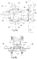
- Fig. 7a
- shows a view from above of the enlarged detail H of Fig. 4a;
- Fig. 7b
- shows the section from I to I of Fig. 7a;
- Fig. 8a
- is a part view from above of a variant of Fig. 1;
- Fig. 8b
- shows the section from L to L of Fig. 8a.
- Figs. 9a and 9b
- show, respectively from above and below, a variant of Figs. 8a and 8b.
- The wood cutting/chopping
machine 10 according to the invention essentially consists of aloading assembly 11 fortrunks 12, afeed assembly 13, a cuttingassembly 14, agripper assembly 29, atranslation assembly 25 and a choppingassembly 15, arranged in sequence. - At outlet of the chopping
assembly 15 there is acarrier assembly 16, in this case a conveyor belt, to transport thesegments 49 produced. - In this case, (Figs. 2a-2b), the
loading assembly 11 comprises a frame to support two pairs oftoothed wheels 17 driven byrespective chains 18; shapedbrackets 19 are associated, at a pre-set distance, to the links of thechains 18, in this case sixbrackets 19 for eachchain 18, to grip, raise and discharge thetrunks 12. - In this case, the
trunks 12 are conveyed from a stacking zone to theloading assembly 11 by means of asloping surface 21. - The
brackets 19 have a surface on which thetrunks 12 rest consisting of a hook-shaped profile which has one part higher towards thechain 18; it is thus possible to prevent thetrunks 12 knocking against thechain 18 as they roll on the slopingsurface 21, and also to supporttrunks 12 of any diameter whatsoever. - The
loading assembly 11 discharges the raisedtrunks 12 one by one onto the slidingchannel 20 of thefeed assembly 13. - In this case, between the loading
assembly 11 and thefeed assembly 13 there is anassembly 58 which temporarily retains thetrunk 12 until thetrolley 22 returns; the saidtrolley 22 feeds the trunks along the slidingchannel 20; afterwards, thetrunks 12 may be discharged onto the slidingchannel 20 of thefeed assembly 13. The cycle times of thefeed assembly 13 are thus not bound to those of theloading assembly 11, which can begin to raise atrunk 12 irrespective of the position of thetrolley 22. - The
assembly 58 comprises a slopingsurface 59 cooperating with a pair ofarms 60 which move alternately from a position ofinterference 60a with thetrunk 12 to a position ofnon-interference 60b which allows thetrunk 12 to roll onto the slidingchannel 20. - This happens when the
trolley 22 which moves in the slidingchannel 20 is in its return end-of-travel position. - The sliding
channel 20 is V-shaped in section, so as to contain thetrunks 12 laterally. - The driven
trolley 22 travels along arail 23, for example a rack rail, moving from a startingposition 22a, at the beginning of the slidingchannel 20, to anend position 22b at the end of the slidingchannel 20. - In this case, the beginning and end of the sliding
channel 20 coincide respectively with the end farthest from and nearest to the cuttingassembly 14. In this case, moreover, the driventrolley 22 includes thruster means 24, an oil dynamic piston in this case, to vary the distance of the end of thetrunk 12 from the body of thetrolley 22. - As can be seen in Fig. 3b, the thruster means 24 may move to any position between a retracted
position 24a and a position ofmaximum extension 24b; it is thus possible, as described later, to thrust, locate and center onto thetranslation assembly 25 also thelast section 12 cut. - In the embodiment shown here, moreover, in order to facilitate the centering operation, there are auxiliary thrust means 47, in this case of the same type as the
means 24 and opposite thereto (Fig. 1). - The cutting
assembly 14, shown in detail in Figs. 4a-4b, has atrolley 55 to support at least one saw 27, in this case with acircular blade 28, driven by means of atransmission belt 62, by anelectric motor 61. Thebelt 62 drives apulley 63 which makes theblade 28 rotate by means of arotary shaft 64. - The supporting
trolley 55 is equipped with ascending/descending motion, in this case driven by a vertical oildynamic actuator 54, so that thecircular blade 28 moves to at least two extreme positions, respectively the lowered position, or position ofnon-interference 28a, and the raised or cuttingposition 28b. - In this embodiment, as can be seen in Fig. 4a, the
blade 28 cuts the trunks from the bottom upwards. - The supporting
trolley 55 can be removed from the frame of the cuttingassembly 14; this facilitates maintenance of thesaw 27. The combined trolley 55-motor 61-saw 27 is assembled on anothertrolley 65 which is able to move transversely with respect to the structure which contains it, to facilitate removal. - The ascending/descending movements of the
trolley 55 are correlated to the advance of thetrolley 22. - To be more exact, the
trolley 22 is made to advance at least from a pre-determined point of the slidingchannel 20 onwards, according to a pitch which defines the length of the individual sections into which thetrunk 12 is divided; the sections correspond to a whole sub-multiple of the overall length of thetrunk 12. - The pitches are calculated by an electronic control and drive
unit 26, for example with programmable logic or similar. - In this case, the
machine 10 has monitoring means, for example optical monitoring means, to monitor the presence of thetrunk 12 loaded onto thefeed assembly 13, and also means to measure the length of the saidtrunk 12. - In one formulation, the means to measure the length of the
trunk 12 comprise an encoder which detects the space covered by thetrolley 22 from the startingposition 22a until it stops, which is when the leading end of thetrunk 12 reaches the proximity of a sensor, such as a photocell, located in correspondence with the beginning of the cuttingassembly 14 or the end of the slidingchannel 20. The control and driveunit 26 processes the data supplied by the encoder and, knowing the length of the slidingchannel 20, calculates the length of thetrunk 12 to be cut. - The
machine 10 thus makes possible to divide thetrunk 12 into sections of equal length and above all to prevent sections of the trailing end from advancing which would have to be discarded. - In this case, during the transverse cutting operation, the
trunks 12 are clamped in position by twogripper assemblies 29 consisting of pantograph arms comprising a pair ofupper arms 30a pivoted in correspondence with the end facing upwards and constrained to the top of the frame of the cuttingassembly 14. - The end of the
upper arms 30a facing downwards pivots onpins 34 at the upper end of respectivelower arms 30b. - The
lower arms 30b in turn pivot on each other by means of apin 31, substantially in correspondence with the center line. - The
pin 31 is able to slide at one end in avertical guide 32 along which it can slide upwards or downwards in response to, respectively, the actions of traction or of thrust exerted by an oildynamic actuator 33 on one only of the twopins 34. When the oildynamic actuator 33 is retracted, the lower ends of thelower arms 30b are lowered, gripping and clamping thetrunk 12 in the cutting position. - When the oil
dynamic actuator 33 is extended, the lower ends of thearms 30b are lifted into the position of non-interference with thetrunk 12. - When the
trunk 12 is clamped, whatever its diameter, thegripper assembly 29 has itslower arms 30b positioned at 120° with respect to the plane on which thetrunk 12 rests. - This allows the control and drive
unit 26 to determine the diameter of thetrunk 12 by means of algorithms based only on the measurement of the travel made by the oildynamic actuator 33. - Due to the fact that the
gripper assembly 29 monitors the diameter of thetrunk 12 before thetrunk 12 is cut, it is possible to establish the travel of the oildynamic actuator 54 to move the supportingtrolley 55 of thesaw 27. Since the diameter is monitored for every section oftrunk 12 cut, it is possible, as described later, to position and center thegrid 43 of the choppingassembly 15 correctly, in order to obtain a number of segments proportional to the diameter and to center the center of thegrid 43 with respect to the center of the section. - When the
blade 28 has cut thetrunk 12 in a transverse direction, a section oftrunk 12 is positioned on thetranslation assembly 25, in this case comprising twotray elements 35 driven by respective oildynamic actuators 36 and aligned with the slidingchannel 20. - On a first lower face, facing towards the chopping
assembly 15, thetray elements 35, in this case V-shaped, havewheels 37 running onguides 38, and on the opposite lower face they are associated with the piston of the oildynamic actuator 36. - When the
trunk 12 is in the cutting position the piston of theactuator 36 is retracted and thetray element 35 is in thecutting position 35a. - When cutting has been completed, the piston of the oil
dynamic actuator 36 is extended so that thetray element 35, sliding onguides 38, progressively moves towards the choppingassembly 15 until it reaches an end-of-travel andturnover position 35b. - In this end-of-travel and
turnover position 35b, thewheels 37 cooperate with a slopingsurface 39 which causes thetray elements 35 to partly turn over forwards, and therefore the cut section oftrunk 12 to turn over onto thetray element 40 of the choppingassembly 15. - By using two
tray elements 35, it is possible to increase the productivity of themachine 10 particularly when producingpieces 49 of firewood of limited length, for example of the type forstoves 20÷25 cm long. - In this case, after the cutting operation, the
section 12 occupies only thetray element 35 nearest thetrolley 22, while theother tray element 35 is free; this allows the thruster means 24 to move to a condition ofmaximum extension 24b to push the already cutsection 12 onto thetray element 35 farthest from thetrolley 22. - At this point the
farthest tray element 35 is activated to turn over the section oftrunk 12 onto thetray element 40 of the choppingassembly 15 while a new section is cut onto thetray element 35 nearest thetrolley 22. - When turnover is completed, the
farthest tray element 35 returns in position to receive the new section oftrunk 12, and the cycle is repeated. - In this case, the
tray element 40 hinges on the side of thethruster element 42 of the choppingassembly 15 and oscillates downwards at the front part contrasted by aspring 41 which allows it to respond elastically to the stresses to which it is subjected when the section oftrunk 12 is chopped; this oscillation, moreover, facilitates the section to open, rose-like, and the lower segments to run out along the grain caused by the chopping action. - The chopping
assembly 15 consists of a frame to support thetray element 40, thethruster element 42 driven by an oildynamic piston 56, associated by means of rods to the rear end of fourcross pieces 57, of which the two upper ones act as guide means for thethruster element 42, and at least achopping grid 43 mounted on a grid-bearing frame. - In this case, the grid-bearing frame consists of two platbands, upper 66a and lower 66b, separated in height by three vertical bars which are aligned with the
vertical chopping blades 48 of each choppinggrid 43. At the side of each choppingblade 48 there are two tubular spacers 53 (the intermediate one is shared by two adjacent grids 43), also attached vertically to the twoplatbands - The
tubular spacers 53 cooperate so that thegrid 43 does not rotate during the chopping step. - The thrust exerted on the grid-bearing frame is contrasted by two small cross pieces, the upper 67a and the lower 67b, attached to the
rods 68 which connect the two heads by means ofbolts 69. - In this case, the
chopping grid 43 is rectangular with its long sides parallel to the plane which supports themachine 10 and cooperates both above and below withwheels 44 located ontubular frames 70 located both above and below therelative platbands - The grid-bearing frame is associated with an oil
dynamic actuator 45, governed by the control and driveunit 26, which allows thechopping grid 43 to be displaced to the left and to the right in a controlled manner. According to a variant, for grids which run vertically, the grid-bearing frame is moved by a driven pinion; in this variant, which is not shown here, thechopping grid 43 has its short sides parallel to the plane supporting themachine 10 and translates vertically. - According to a further variant, the
chopping grid 43 is circular or similar, and can rotate around its center. - The translation or, possibly, rotation movements of the
chopping grid 43 make possible to vary the size, number and/or shape of thesegments 49 obtained according to necessity, and to center the grid with respect to the section oftrunk 12. - In this case, the
chopping grid 43 is divided into three sectors, respectively left 43a, central 43b and right 43c, each one characterised by a different arrangement of thechopping blades 48. - To be more exact, the
right sector 43c is used to chop sections oftrunk 12 of limited diameter, and thechopping blades 48 are arranged in a cross to divide the sections oftrunk 12 into quarters. - In the right sector, moreover, the
chopping blade 48 arranged horizontally is movable upwards or downwards, which allows to move it to a position of non-interference to divide the section oftrunk 12 in half. - The
central sector 43b is used to chop sections oftrunk 12 with medium diameters, and thechopping blades 48 are arranged in a dial to allow the sections oftrunk 12 to be divided into six parts. - The
left sector 43c is used to chop sections oftrunk 12 with a large diameter, and thechopping blades 48 are arranged in a dial to divide the sections into eight parts. - According to the invention, when one of the
sectors tray element 40 supporting the section oftrunk 12 to be chopped, thethruster element 42 moves progressively from a start-of-choppingposition 42a to an end-of-chopping position 42b, progressively pushing the section oftrunk 12 towards the choppingblades 48. - The positioning of a
specific sector tray element 40 is automatically managed by the control and driveunit 26; according to a variant, this positioning is commanded by the operator. - The automatic positioning of a
specific sector tray element 40, and the centering of the point of intersection of thechopping blades 48 with the center of the section to be chopped is made possible, as already described, by the means to measure the diameter, associated with thegripper assembly 29. - To be more exact, the data supplied by the diameter measuring means is processed by the control and drive
unit 26 which activates the oildynamic actuator 45, or the movement means otherwise provided, to locate thesector trunk 12 being worked. - Moreover, the control and drive
unit 26 centers the center of the grid with respect to the center of the section to be chopped. - As can be seen from Figs. 5a, 5b, there is an oil
dynamic actuator 50 associated, by means of a grooved bar 51 crossing above thegrid 43, with thechopping blades 48 of thechopping grid 43; thechopping blades 48 are associated with thechopping grid 43 by means of holed fork means 52 which slide along thetubular spacers 53 of thechopping grid 43. - The grooved bar 51 can rotate by means of a pinion and
rack 71 to drive the oildynamic actuator 50, which allows to move vertically the grid-bearing frame so as to carry out this centering. - In this case, the
pieces 49 of chopped firewood fall onto thecarrier assembly 16 which conveys them to a storage zone or directly into the containing body of a truck. - The variant shown in Figs. 8a-8b, 9a, 9b is used in the
machine 10 as an alternative to thetranslation assembly 25 to move the sections oftrunks 12 cut to size from the cuttingassembly 14 to the choppingassembly 15. - This embodiment, which considerably increases the productivity of the
machine 10, includes arotary disk 72 underneath the choppingassembly 15. - At the ends of two orthogonal diameters, the
rotary disk 72 hasrespective tray elements 46, in this case four arranged at 90° to each other, cushioned like thetray element 40 as described above, which in this case is absent inasmuch as thetrays 46 perform both the function of thetray 35 of thetranslation assembly 25 and also the function of thetray 40 of the choppingassembly 15. - In this embodiment, in fact, the section of
trunk 12 is supported, both during the cutting operation and during the chopping operation, by theindividual tray elements 46 which, following the rotations of thedisk 72, move one by one opposite thethruster element 42, transporting one section. With this variant, thefeed assembly 13 and the cuttingassembly 14 are rotated in a clockwise direction by 90° with respect to Fig. 1, which allows the section cut by the cuttingassembly 14 to be arranged lengthwise to thetray element 46 and to move in correspondence with thethruster element 42 with the fibres orthogonal with respect to thechopping blades 48. - As can be seen in Fig. 9a, the
trunk 12 is fed by thefeed assembly 13 which is not shown here and arrives, moved at pitch, from the direction of the arrow A; it is positioned with its front end, calculated to size, on thetray 46 in position I. - Then, the
saw 27 acts on thetrunk 12 and cuts the section located on thetray 46; then therotary disk 72 rotates by 90° and positions the cut section in correspondence with the position indicated as II. - This position II of the
tray 46 is aligned with the axis of thethruster element 42 and with thechopping grids 43; when thethruster element 42 is activated, this causes the section to be chopped intopieces 49. - When one section has been chopped, the
thruster element 42 retracts and a new section, cut by thesaw 27 during the previous chopping cycle, is taken to the chopping position by the rotation of thedisk 72. - The
tray 46, in the chopping position II, cooperates at the lower part with a shock absorber element consisting of asupport 75 associated with spring means 41. - The
support 75, elastically yielding to the pressure exerted by the section oftrunk 12 during the chopping action, facilitates and makes the chopping action qualitatively better, preventing the chopping blades of thegrid 43 from jamming against the cutting surfaces, and ruining them. - In this case, as can be seen in Fig. 9a, the center of
rotation 73 of therotary disk 72 is displaced sideways with respect to the cuttingaxis 74 of thesaw 27, which coincides with the axis of arrival of the trunk which is to be cut as fed by thefeed assembly 13; this prevents interference, during the rotation of thedisk 72, between the front end of thetrays 46 and elements of the cuttingassembly 14 or other structural elements of themachine 10.
Claims (31)
- Automatic electronic wood cutting/chopping machine used to produce pieces or segments (49) of firewood from branchless trunks (12) and collected from a stacking zone, the machine being characterised in that it includes, in coordinated cooperation, a loading assembly (11) to automatically pick up the trunks (12) from the stacking zone and to deposit them on a lengthwise feed assembly (13) with a sliding channel (20), a cutting assembly (14) located to follow the lengthwise feed assembly (13) to divide the trunks (12) into sections of pre-determined length, a gripper assembly (29) located in cooperation with the cutting assembly (14) to temporarily retain the trunks (12) during the cutting operation and to measure the diameter of the trunks (12), a translation assembly (25) located immediately downstream of the cutting assembly (14) to translate the cut sections of trunk (12), a chopping assembly (15), complanar and substantially adjacent to the feed assembly (13), to divide the cut sections into a defined number of pieces or segments (49) and a carrier assembly (16) located immediately downstream of the chopping assembly (15) to discharge and/or separate the pieces or segments (49) produced, the assemblies (11,13,14,15,16,25, 29) being governed by an electronic control and drive unit (26) associated at least with means to automatically determine the length of the trunks (12).
- Machine as in Claim 1, characterised in that the chopping assembly (15) comprises a thruster element (42) cooperating at the lower part with a tray element (40, 46) to support the section of trunk (12) to be chopped and at the front with a chopping grid (43) with multiple sectors (43a,43b,43c), each sector (43a,43b,43c) of the grid (43) having relative chopping blades (48) defining a different arrangement or pattern.
- Machine as in Claim 2, characterised in that the grid (43) is associated with a grid-bearing frame movable on the plane on which the thruster element (42) lies.
- Machine as in Claim 2, characterised in that the grid (43) is associated with a grid-bearing frame movable orthogonally to the plane on which the thruster element (42) lies.
- Machine as in any claim hereinbefore, characterised in that the grid-bearing frame is associated with positioning means (45) governed by the electronic control and drive unit (26) according to the diameter of the section of trunk (12) to be chopped and/or of the sector (43a,43b,43c) to be positioned.
- Machine as in any claim hereinbefore, characterised in that the grid-bearing frame is associated with position adjustment means (50, 51) according to the collimation of the center of the sector (43a,43b,43c) with respect to the center of the section of trunk (12).
- Machine as in any claim hereinbefore, characterised in that the grid-bearing frame comprises two platbands (66a, 66b), parallel to the cutting plane, solidly constrained to the chopping blades (48) and to the tubular spacers (57) transverse thereto, the grid-bearing frame also comprising small cross pieces (67a,76b) solid with the rods (68) which connect the heads of the machine.
- Machine as in any claim hereinbefore, characterised in that the tray element (40, 46) is able to oscillate at the front according to the stresses imparted by the section of trunk (12) during the chopping operation.
- Machine as in Claim 8, characterised in that the tray element (40, 46) is hinged at the lower part on the side facing the thruster element (42) and cooperates with elastic contrasting means (41) on the opposite side.
- Machine as in Claim 1, characterised in that the feed assembly (13) is movable lengthwise at pitch, each pitch being functional to a sub-multiple of the length of the trunk (12).
- Machine as in Claim 10, characterised in that the feed assembly (13) comprises a sliding channel (20) for the trunk (12) cooperating with thruster means (24) associated with a trolley (22), the trolley (22) including a start position (22a) cooperating with the beginning of the sliding channel (20) and an end position (22b) cooperating with the end of the sliding channel (20).
- Machine as in Claim 11, characterised in that the sliding channel (20) comprises means to automatically determine the length of the trunk (12).
- Machine as in Claim 11 or 12, characterised in that the thruster means (24) can be moved so as to center the cut sections of trunk (12) on the translation assembly (25).
- Machine as in Claim 1, characterised in that the gripper assembly (29) includes means to measure the diameter of the cut section.
- Machine as in Claim 14, characterised in that the gripper assembly (29) comprises pantograph arms (30a,30b), a first upper pair (30a) of the arms having their upper ends pivoted at a same point at the top of the frame of the cutting assembly (14) and the lower ends pivoted with pins (34) at the upper end of respective lower arms, the lower arms (30b) being in turn pivoted together on a pin (31) substantially in correspondence with the center line, the pin (31) being able to slide along a vertical guide (32) in response to the actions of traction or thrust exerted by an actuator (33) acting on one only of the two pins (34).
- Machine as in Claim 15, characterised in that the lower ends of the lower arms (30b) have a first lowered position wherein the trunk (12) is clamped in the cutting position associated with the retracted position of the actuator (33) and a second raised position of non-interference associated with the extended position of the actuator (33).
- Machine as in any claim from 14 to 16 inclusive, characterised in that the means to measure the diameter of the section comprise an actuator to determine the travel made by the actuator (33).
- Machine as in any claim from 14 to 17 inclusive, characterised in that the lower arms (30b), whatever the diameter of the trunk (12), are always arranged at 120° with respect to the plane on which the trunk (12) lies.
- Machine as in Claim 1, characterised in that the cutting assembly (14) has at least a saw (27) with a circular blade (28) associated with a supporting trolley (55) movable vertically and defining, for the blade (28), a first lowered position (28a) of non-interference and a second, raised position (28a) for cutting.
- Machine as in Claim 19, characterised in that the supporting trolley (55) is driven by actuators (54) which are able to move according to the diameter of the trunk (12).
- Machine as in Claim 19, characterised in that the supporting trolley (55) can be removed from the bearing structure of the machine (10).
- Machine as in Claim 1, characterised in that the translation assembly (25) comprises tray elements (35,46).
- Machine as in Claim 22, characterised in that the tray element (35) is associated at one end with an actuator (36) and has a cutting position (35a) cooperating with the cutting assembly (14) and an end-of-travel and turnover position (35b) wherein it discharges the cut section (12) onto the chopping assembly (15).
- Machine as in Claim 22, characterised in that there are two tray elements (35), a first tray element (35) supporting one section of trunk (12) still to be cut and a second tray element (35) discharging the section which has already been cut on the first tray element (35) and then thrust therefrom onto the second tray element (35).
- Machine as in Claim 22, characterised in that the tray elements (46) are associated with a rotary disk (72).
- Machine as in Claim 25, characterised in that the rotary disk (72) is suitable to move a tray (46) from a first position (I) aligned with the lengthwise feed assembly (13) wherein the trunk to be cut is received, to a second position (II) aligned with the axis of the chopping grid (43) wherein the section of cut trunk (12) is chopped.
- Machine as in Claim 25 or 26, characterised in that the rotary disk (72) rotates around an axis of rotation (73) laterally displaced with respect to the axis of feed (74) of the feed assembly (13).
- Machine as in Claim 1, characterised in that the loading assembly (11) has pairs of driven toothed wheels (17) driving chains (18) having links to which are associated bracket elements (19) to support and raise the trunks (12) to a desired height.
- Machine as in Claim 28, characterised in that the bracket elements (19) have a hook-shaped profile.
- Machine as in Claim 28, characterised in that upstream of the loading assembly (11) there is a sloping surface (21) over which the trunks (12) arriving from the stacking zone are rolled.
- Machine as in Claim 28, characterised in that downstream of the loading assembly (11) there is a an assembly (58) to temporarily retain the raised trunks (12) before they are discharged onto the feed assembly (13).
Applications Claiming Priority (2)
| Application Number | Priority Date | Filing Date | Title |
|---|---|---|---|
| IT97UD000155A IT1294630B1 (en) | 1997-09-11 | 1997-09-11 | AUTOMATIC ELECTRONIC WOOD CUTTER / SPLIT MACHINE |
| ITUD970155 | 1997-09-11 |
Publications (3)
| Publication Number | Publication Date |
|---|---|
| EP0901892A2 true EP0901892A2 (en) | 1999-03-17 |
| EP0901892A3 EP0901892A3 (en) | 1999-05-19 |
| EP0901892B1 EP0901892B1 (en) | 2001-11-21 |
Family
ID=11422453
Family Applications (1)
| Application Number | Title | Priority Date | Filing Date |
|---|---|---|---|
| EP98117133A Revoked EP0901892B1 (en) | 1997-09-11 | 1998-09-10 | Automatic electronic wood cutting/chopping machine |
Country Status (6)
| Country | Link |
|---|---|
| EP (1) | EP0901892B1 (en) |
| AT (1) | ATE209086T1 (en) |
| DE (1) | DE69803259T2 (en) |
| DK (1) | DK0901892T3 (en) |
| ES (1) | ES2167825T3 (en) |
| IT (1) | IT1294630B1 (en) |
Cited By (10)
| Publication number | Priority date | Publication date | Assignee | Title |
|---|---|---|---|---|
| EP1440778A2 (en) * | 2003-01-24 | 2004-07-28 | Mauro Pinosa | Machine for preparing firewood |
| FR2871720A1 (en) * | 2004-06-16 | 2005-12-23 | Espace Bois Services Entpr Uni | Match stick obtaining process, involves pushing firewood against fixed blades to obtain match sticks, where blades are moved angularly based on their diameters and are disposed on conduit |
| FR2948054A1 (en) * | 2009-07-16 | 2011-01-21 | Rabaud Sa | Installation for cutting wood logs/billets by sawing/splitting, has calculating unit associated to detection unit to calculate volume of cut wood by considering diameter and length of billets, and informing unit informing volume to operator |
| WO2011141636A1 (en) * | 2010-05-14 | 2011-11-17 | Reikälevy Oy | Cutting and splitting device |
| ITUD20130121A1 (en) * | 2013-09-17 | 2015-03-18 | Forenergy Di Luigi Pinosa Impresa I Ndividuale | MACHINERY AND PROCEDURE FOR PROCESSING TRUNKS, RAMAGLAMES OR THE LIKE |
| KR101517211B1 (en) | 2013-05-30 | 2015-05-06 | 김곤 | Cutting device for forming the wood pellet |
| EP3205466A1 (en) * | 2016-02-10 | 2017-08-16 | Ylistaron Terästakomo Oy | A firewood processor with a movable splitting wedge |
| EP2684657B1 (en) * | 2012-07-11 | 2017-11-22 | Regon AY | Firewood processor |
| CN108858470A (en) * | 2018-07-26 | 2018-11-23 | 贵州鑫大福门业有限公司 | Cut-to-size saw with guiding device |
| EP3415294A1 (en) * | 2017-06-13 | 2018-12-19 | Agromaster Oy | Splitting blade structure for a firewood processor |
Families Citing this family (6)
| Publication number | Priority date | Publication date | Assignee | Title |
|---|---|---|---|---|
| DE10354265B4 (en) * | 2002-11-19 | 2006-05-04 | Glasschröder, Adolf | Double wood splitter |
| DE10302906A1 (en) * | 2003-01-24 | 2004-08-05 | Christian Kessler | Woodworking device |
| DE102006001025B3 (en) * | 2006-01-04 | 2007-08-23 | Christian Beckereit | Log splitting device, comprises splitting blades arranged in V- or X-shape following direction of grain |
| DE202013008587U1 (en) * | 2013-09-27 | 2015-01-09 | Gert Weersmann | Log splitter (horizontal splitter) with a flywheel drive |
| DE102014110968A1 (en) * | 2014-08-01 | 2016-02-04 | Stader Metall Gmbh & Co. Kg | Wood saw and wood splitter for sawing and splitting wood |
| CN106272767B (en) * | 2016-10-10 | 2019-03-08 | 南宁职业技术学院 | A kind of novel bamboo tube is broken to cut machine |
Citations (9)
| Publication number | Priority date | Publication date | Assignee | Title |
|---|---|---|---|---|
| US4160470A (en) * | 1978-03-13 | 1979-07-10 | Timbern, Ltd. | Log shearing and splitting device |
| US4281697A (en) * | 1977-08-04 | 1981-08-04 | Lafont Corporation | Firewood systems |
| US4284112A (en) * | 1977-12-14 | 1981-08-18 | Hoskin Charles E | Automatic wood cutting and splitting machine |
| US4294295A (en) * | 1978-09-25 | 1981-10-13 | Bloomfield Farms, Inc. | Apparatus for cutting and splitting firewood |
| US4373564A (en) * | 1980-11-13 | 1983-02-15 | Heikkinen Leo L | Self-propelled wood processing apparatus |
| EP0097245A1 (en) * | 1982-05-18 | 1984-01-04 | Walter Kretzer | Device for automatically processing logs |
| US4834154A (en) * | 1988-08-31 | 1989-05-30 | The Nunnery Wood Processor Co. | Firewood processor |
| FR2716831A1 (en) * | 1994-03-03 | 1995-09-08 | Critt Bois | Optimisation of value or volume in splitting logs |
| US5791389A (en) * | 1997-03-28 | 1998-08-11 | Yvonne Company | Apparatus and method for forming firewood logs |
-
1997
- 1997-09-11 IT IT97UD000155A patent/IT1294630B1/en active IP Right Grant
-
1998
- 1998-09-10 EP EP98117133A patent/EP0901892B1/en not_active Revoked
- 1998-09-10 AT AT98117133T patent/ATE209086T1/en not_active IP Right Cessation
- 1998-09-10 DE DE69803259T patent/DE69803259T2/en not_active Revoked
- 1998-09-10 ES ES98117133T patent/ES2167825T3/en not_active Expired - Lifetime
- 1998-09-10 DK DK98117133T patent/DK0901892T3/en active
Patent Citations (9)
| Publication number | Priority date | Publication date | Assignee | Title |
|---|---|---|---|---|
| US4281697A (en) * | 1977-08-04 | 1981-08-04 | Lafont Corporation | Firewood systems |
| US4284112A (en) * | 1977-12-14 | 1981-08-18 | Hoskin Charles E | Automatic wood cutting and splitting machine |
| US4160470A (en) * | 1978-03-13 | 1979-07-10 | Timbern, Ltd. | Log shearing and splitting device |
| US4294295A (en) * | 1978-09-25 | 1981-10-13 | Bloomfield Farms, Inc. | Apparatus for cutting and splitting firewood |
| US4373564A (en) * | 1980-11-13 | 1983-02-15 | Heikkinen Leo L | Self-propelled wood processing apparatus |
| EP0097245A1 (en) * | 1982-05-18 | 1984-01-04 | Walter Kretzer | Device for automatically processing logs |
| US4834154A (en) * | 1988-08-31 | 1989-05-30 | The Nunnery Wood Processor Co. | Firewood processor |
| FR2716831A1 (en) * | 1994-03-03 | 1995-09-08 | Critt Bois | Optimisation of value or volume in splitting logs |
| US5791389A (en) * | 1997-03-28 | 1998-08-11 | Yvonne Company | Apparatus and method for forming firewood logs |
Cited By (15)
| Publication number | Priority date | Publication date | Assignee | Title |
|---|---|---|---|---|
| EP1440778A2 (en) * | 2003-01-24 | 2004-07-28 | Mauro Pinosa | Machine for preparing firewood |
| EP1440778A3 (en) * | 2003-01-24 | 2005-06-22 | Mauro Pinosa | Machine for preparing firewood |
| FR2871720A1 (en) * | 2004-06-16 | 2005-12-23 | Espace Bois Services Entpr Uni | Match stick obtaining process, involves pushing firewood against fixed blades to obtain match sticks, where blades are moved angularly based on their diameters and are disposed on conduit |
| FR2948054A1 (en) * | 2009-07-16 | 2011-01-21 | Rabaud Sa | Installation for cutting wood logs/billets by sawing/splitting, has calculating unit associated to detection unit to calculate volume of cut wood by considering diameter and length of billets, and informing unit informing volume to operator |
| EP2569133A4 (en) * | 2010-05-14 | 2014-01-15 | Reikaelevy Oy | Cutting and splitting device |
| EP2569133A1 (en) * | 2010-05-14 | 2013-03-20 | Reikälevy Oy, . | Cutting and splitting device |
| WO2011141636A1 (en) * | 2010-05-14 | 2011-11-17 | Reikälevy Oy | Cutting and splitting device |
| US10464149B2 (en) | 2010-05-14 | 2019-11-05 | Reikalevy Oy | Cutting and splitting device |
| EP2684657B1 (en) * | 2012-07-11 | 2017-11-22 | Regon AY | Firewood processor |
| KR101517211B1 (en) | 2013-05-30 | 2015-05-06 | 김곤 | Cutting device for forming the wood pellet |
| ITUD20130121A1 (en) * | 2013-09-17 | 2015-03-18 | Forenergy Di Luigi Pinosa Impresa I Ndividuale | MACHINERY AND PROCEDURE FOR PROCESSING TRUNKS, RAMAGLAMES OR THE LIKE |
| EP3205466A1 (en) * | 2016-02-10 | 2017-08-16 | Ylistaron Terästakomo Oy | A firewood processor with a movable splitting wedge |
| EP3415294A1 (en) * | 2017-06-13 | 2018-12-19 | Agromaster Oy | Splitting blade structure for a firewood processor |
| CN108858470A (en) * | 2018-07-26 | 2018-11-23 | 贵州鑫大福门业有限公司 | Cut-to-size saw with guiding device |
| CN108858470B (en) * | 2018-07-26 | 2020-08-11 | 贵州鑫大福门业有限公司 | Plate cutting saw with guide device |
Also Published As
| Publication number | Publication date |
|---|---|
| DE69803259T2 (en) | 2002-08-08 |
| ATE209086T1 (en) | 2001-12-15 |
| DE69803259D1 (en) | 2002-02-21 |
| DK0901892T3 (en) | 2002-05-13 |
| IT1294630B1 (en) | 1999-04-12 |
| EP0901892A3 (en) | 1999-05-19 |
| ES2167825T3 (en) | 2002-05-16 |
| ITUD970155A1 (en) | 1999-03-11 |
| EP0901892B1 (en) | 2001-11-21 |
Similar Documents
| Publication | Publication Date | Title |
|---|---|---|
| EP0901892B1 (en) | Automatic electronic wood cutting/chopping machine | |
| US4078592A (en) | Log feed mechanism for sawmills | |
| CN107443508B (en) | Automatic feeding and section fixing equipment for bamboo wood | |
| CN107877006B (en) | Full-automatic numerical control laser pipe cutting machine | |
| US4340137A (en) | Cant movement and aligning mechanism | |
| CA2077777C (en) | Ending apparatus and method | |
| US4907632A (en) | Process and apparatus for the feeding of tree trunks to a processing machine | |
| KR960006832B1 (en) | Workpiece conveying device and method for a cutting machine | |
| CA2218171C (en) | Automated infeed system | |
| US4628781A (en) | Lumber mill system | |
| US6279441B1 (en) | System and apparatus for cutting logs into shorter lengths | |
| US20110253261A1 (en) | Automatic Workpiece Edging and Ripping Device and Method | |
| EP0316256A2 (en) | Method and apparatus for pretreating and debarking logs | |
| US20040016334A1 (en) | Log merchandiser | |
| CA2190339A1 (en) | Saw carriage | |
| CN206588675U (en) | Long bar fixed length conveying and collection device | |
| CN210477266U (en) | Cut open bamboo machine material loading structure | |
| CN214269266U (en) | Feeding device for conveying pipes one by one | |
| CN215316069U (en) | Variable angle sawing line | |
| CN210477226U (en) | Adjustable log double-side processing machine | |
| CN106975966A (en) | Long bar fixed length conveying and collection device | |
| CN109318284B (en) | Continuous feeding type semi-automatic bean curd dicer | |
| US3138258A (en) | Method and apparatus for sorting automatically logs and like objects | |
| EP1258306A2 (en) | System for detecting size unevennesses of cut-stock boards | |
| CN219748356U (en) | Saw bamboo machine |
Legal Events
| Date | Code | Title | Description |
|---|---|---|---|
| PUAI | Public reference made under article 153(3) epc to a published international application that has entered the european phase |
Free format text: ORIGINAL CODE: 0009012 |
|
| AK | Designated contracting states |
Kind code of ref document: A2 Designated state(s): AT BE CH DE DK ES FR GB IT LI NL PT SE |
|
| AX | Request for extension of the european patent |
Free format text: AL;LT;LV;MK;RO;SI |
|
| PUAL | Search report despatched |
Free format text: ORIGINAL CODE: 0009013 |
|
| AK | Designated contracting states |
Kind code of ref document: A3 Designated state(s): AT BE CH CY DE DK ES FI FR GB GR IE IT LI LU MC NL PT SE |
|
| AX | Request for extension of the european patent |
Free format text: AL;LT;LV;MK;RO;SI |
|
| AKX | Designation fees paid |
Free format text: AT BE CH DE DK ES FR GB IT LI NL PT SE |
|
| AXX | Extension fees paid |
Free format text: SI PAYMENT 19991122 |
|
| 17P | Request for examination filed |
Effective date: 19991118 |
|
| RAX | Requested extension states of the european patent have changed |
Free format text: SI PAYMENT 19991118 |
|
| RBV | Designated contracting states (corrected) |
Designated state(s): AT BE CH DE DK ES FR GB IT LI NL PT SE |
|
| RAP1 | Party data changed (applicant data changed or rights of an application transferred) |
Owner name: PINOSA SRL |
|
| RIN1 | Information on inventor provided before grant (corrected) |
Inventor name: ORLANDO, MAURIZIO Inventor name: DELLA ROSSA, ERCOLE |
|
| GRAG | Despatch of communication of intention to grant |
Free format text: ORIGINAL CODE: EPIDOS AGRA |
|
| GRAG | Despatch of communication of intention to grant |
Free format text: ORIGINAL CODE: EPIDOS AGRA |
|
| GRAH | Despatch of communication of intention to grant a patent |
Free format text: ORIGINAL CODE: EPIDOS IGRA |
|
| 17Q | First examination report despatched |
Effective date: 20010402 |
|
| GRAH | Despatch of communication of intention to grant a patent |
Free format text: ORIGINAL CODE: EPIDOS IGRA |
|
| GRAA | (expected) grant |
Free format text: ORIGINAL CODE: 0009210 |
|
| AK | Designated contracting states |
Kind code of ref document: B1 Designated state(s): AT BE CH DE DK ES FR GB IT LI NL PT SE |
|
| AX | Request for extension of the european patent |
Free format text: SI PAYMENT 19991118 |
|
| REF | Corresponds to: |
Ref document number: 209086 Country of ref document: AT Date of ref document: 20011215 Kind code of ref document: T |
|
| REG | Reference to a national code |
Ref country code: CH Ref legal event code: EP |
|
| REG | Reference to a national code |
Ref country code: GB Ref legal event code: IF02 |
|
| REG | Reference to a national code |
Ref country code: CH Ref legal event code: NV Representative=s name: MICHELI & CIE INGENIEURS-CONSEILS |
|
| PG25 | Lapsed in a contracting state [announced via postgrant information from national office to epo] |
Ref country code: SE Free format text: LAPSE BECAUSE OF FAILURE TO SUBMIT A TRANSLATION OF THE DESCRIPTION OR TO PAY THE FEE WITHIN THE PRESCRIBED TIME-LIMIT Effective date: 20020221 Ref country code: PT Free format text: LAPSE BECAUSE OF FAILURE TO SUBMIT A TRANSLATION OF THE DESCRIPTION OR TO PAY THE FEE WITHIN THE PRESCRIBED TIME-LIMIT Effective date: 20020221 |
|
| REF | Corresponds to: |
Ref document number: 69803259 Country of ref document: DE Date of ref document: 20020221 |
|
| PLBQ | Unpublished change to opponent data |
Free format text: ORIGINAL CODE: EPIDOS OPPO |
|
| REG | Reference to a national code |
Ref country code: ES Ref legal event code: FG2A Ref document number: 2167825 Country of ref document: ES Kind code of ref document: T3 |
|
| PLBI | Opposition filed |
Free format text: ORIGINAL CODE: 0009260 |
|
| 26 | Opposition filed |
Opponent name: PEZZOLATO OFFICINE COSTRUCIONI MECCANICHE SPA Effective date: 20020507 |
|
| NLR1 | Nl: opposition has been filed with the epo |
Opponent name: PEZZOLATO OFFICINE COSTRUCIONI MECCANICHE SPA |
|
| PLBF | Reply of patent proprietor to notice(s) of opposition |
Free format text: ORIGINAL CODE: EPIDOS OBSO |
|
| PLBF | Reply of patent proprietor to notice(s) of opposition |
Free format text: ORIGINAL CODE: EPIDOS OBSO |
|
| PLCK | Communication despatched that opposition was rejected |
Free format text: ORIGINAL CODE: EPIDOSNREJ1 |
|
| APBP | Date of receipt of notice of appeal recorded |
Free format text: ORIGINAL CODE: EPIDOSNNOA2O |
|
| APAH | Appeal reference modified |
Free format text: ORIGINAL CODE: EPIDOSCREFNO |
|
| PGFP | Annual fee paid to national office [announced via postgrant information from national office to epo] |
Ref country code: AT Payment date: 20060914 Year of fee payment: 9 Ref country code: CH Payment date: 20060914 Year of fee payment: 9 |
|
| PGFP | Annual fee paid to national office [announced via postgrant information from national office to epo] |
Ref country code: NL Payment date: 20060915 Year of fee payment: 9 Ref country code: DK Payment date: 20060915 Year of fee payment: 9 |
|
| PGFP | Annual fee paid to national office [announced via postgrant information from national office to epo] |
Ref country code: GB Payment date: 20060921 Year of fee payment: 9 |
|
| PGFP | Annual fee paid to national office [announced via postgrant information from national office to epo] |
Ref country code: FR Payment date: 20060922 Year of fee payment: 9 |
|
| PGFP | Annual fee paid to national office [announced via postgrant information from national office to epo] |
Ref country code: DE Payment date: 20060926 Year of fee payment: 9 |
|
| PGFP | Annual fee paid to national office [announced via postgrant information from national office to epo] |
Ref country code: ES Payment date: 20060928 Year of fee payment: 9 |
|
| PGFP | Annual fee paid to national office [announced via postgrant information from national office to epo] |
Ref country code: BE Payment date: 20061012 Year of fee payment: 9 |
|
| APBQ | Date of receipt of statement of grounds of appeal recorded |
Free format text: ORIGINAL CODE: EPIDOSNNOA3O |
|
| APBU | Appeal procedure closed |
Free format text: ORIGINAL CODE: EPIDOSNNOA9O |
|
| RDAF | Communication despatched that patent is revoked |
Free format text: ORIGINAL CODE: EPIDOSNREV1 |
|
| RDAG | Patent revoked |
Free format text: ORIGINAL CODE: 0009271 |
|
| STAA | Information on the status of an ep patent application or granted ep patent |
Free format text: STATUS: PATENT REVOKED |
|
| 27W | Patent revoked |
Effective date: 20070706 |
|
| GBPR | Gb: patent revoked under art. 102 of the ep convention designating the uk as contracting state |
Free format text: 20070706 |
|
| REG | Reference to a national code |
Ref country code: CH Ref legal event code: PL |
|
| NLR2 | Nl: decision of opposition |
Effective date: 20070706 |
|
| PGFP | Annual fee paid to national office [announced via postgrant information from national office to epo] |
Ref country code: IT Payment date: 20140926 Year of fee payment: 17 |