EP0901595B1 - Nouvel accumulateur - Google Patents
Nouvel accumulateur Download PDFInfo
- Publication number
- EP0901595B1 EP0901595B1 EP97929792A EP97929792A EP0901595B1 EP 0901595 B1 EP0901595 B1 EP 0901595B1 EP 97929792 A EP97929792 A EP 97929792A EP 97929792 A EP97929792 A EP 97929792A EP 0901595 B1 EP0901595 B1 EP 0901595B1
- Authority
- EP
- European Patent Office
- Prior art keywords
- piston
- seal
- liquid
- shoulders
- gas
- Prior art date
- Legal status (The legal status is an assumption and is not a legal conclusion. Google has not performed a legal analysis and makes no representation as to the accuracy of the status listed.)
- Expired - Lifetime
Links
- 239000007788 liquid Substances 0.000 claims description 53
- 230000006835 compression Effects 0.000 claims description 5
- 238000007906 compression Methods 0.000 claims description 5
- 239000012530 fluid Substances 0.000 abstract description 22
- 239000002184 metal Substances 0.000 abstract 1
- 238000004321 preservation Methods 0.000 abstract 1
- 239000013585 weight reducing agent Substances 0.000 abstract 1
- 239000007789 gas Substances 0.000 description 35
- IJGRMHOSHXDMSA-UHFFFAOYSA-N Atomic nitrogen Chemical compound N#N IJGRMHOSHXDMSA-UHFFFAOYSA-N 0.000 description 2
- 230000008901 benefit Effects 0.000 description 2
- 239000000463 material Substances 0.000 description 2
- 238000007789 sealing Methods 0.000 description 2
- 230000003068 static effect Effects 0.000 description 2
- 239000003570 air Substances 0.000 description 1
- 238000013459 approach Methods 0.000 description 1
- 230000001010 compromised effect Effects 0.000 description 1
- 230000001351 cycling effect Effects 0.000 description 1
- 239000001307 helium Substances 0.000 description 1
- 229910052734 helium Inorganic materials 0.000 description 1
- SWQJXJOGLNCZEY-UHFFFAOYSA-N helium atom Chemical compound [He] SWQJXJOGLNCZEY-UHFFFAOYSA-N 0.000 description 1
- 239000010720 hydraulic oil Substances 0.000 description 1
- 230000001939 inductive effect Effects 0.000 description 1
- 229910052757 nitrogen Inorganic materials 0.000 description 1
- 230000001105 regulatory effect Effects 0.000 description 1
- 230000000284 resting effect Effects 0.000 description 1
Images


Classifications
-
- F—MECHANICAL ENGINEERING; LIGHTING; HEATING; WEAPONS; BLASTING
- F15—FLUID-PRESSURE ACTUATORS; HYDRAULICS OR PNEUMATICS IN GENERAL
- F15B—SYSTEMS ACTING BY MEANS OF FLUIDS IN GENERAL; FLUID-PRESSURE ACTUATORS, e.g. SERVOMOTORS; DETAILS OF FLUID-PRESSURE SYSTEMS, NOT OTHERWISE PROVIDED FOR
- F15B1/00—Installations or systems with accumulators; Supply reservoir or sump assemblies
- F15B1/02—Installations or systems with accumulators
- F15B1/04—Accumulators
- F15B1/08—Accumulators using a gas cushion; Gas charging devices; Indicators or floats therefor
- F15B1/22—Liquid port constructions
-
- F—MECHANICAL ENGINEERING; LIGHTING; HEATING; WEAPONS; BLASTING
- F15—FLUID-PRESSURE ACTUATORS; HYDRAULICS OR PNEUMATICS IN GENERAL
- F15B—SYSTEMS ACTING BY MEANS OF FLUIDS IN GENERAL; FLUID-PRESSURE ACTUATORS, e.g. SERVOMOTORS; DETAILS OF FLUID-PRESSURE SYSTEMS, NOT OTHERWISE PROVIDED FOR
- F15B1/00—Installations or systems with accumulators; Supply reservoir or sump assemblies
- F15B1/02—Installations or systems with accumulators
- F15B1/04—Accumulators
- F15B1/08—Accumulators using a gas cushion; Gas charging devices; Indicators or floats therefor
- F15B1/10—Accumulators using a gas cushion; Gas charging devices; Indicators or floats therefor with flexible separating means
- F15B1/103—Accumulators using a gas cushion; Gas charging devices; Indicators or floats therefor with flexible separating means the separating means being bellows
-
- F—MECHANICAL ENGINEERING; LIGHTING; HEATING; WEAPONS; BLASTING
- F16—ENGINEERING ELEMENTS AND UNITS; GENERAL MEASURES FOR PRODUCING AND MAINTAINING EFFECTIVE FUNCTIONING OF MACHINES OR INSTALLATIONS; THERMAL INSULATION IN GENERAL
- F16L—PIPES; JOINTS OR FITTINGS FOR PIPES; SUPPORTS FOR PIPES, CABLES OR PROTECTIVE TUBING; MEANS FOR THERMAL INSULATION IN GENERAL
- F16L55/00—Devices or appurtenances for use in, or in connection with, pipes or pipe systems
- F16L55/04—Devices damping pulsations or vibrations in fluids
- F16L55/045—Devices damping pulsations or vibrations in fluids specially adapted to prevent or minimise the effects of water hammer
- F16L55/05—Buffers therefor
- F16L55/052—Pneumatic reservoirs
- F16L55/053—Pneumatic reservoirs the gas in the reservoir being separated from the fluid in the pipe
-
- F—MECHANICAL ENGINEERING; LIGHTING; HEATING; WEAPONS; BLASTING
- F15—FLUID-PRESSURE ACTUATORS; HYDRAULICS OR PNEUMATICS IN GENERAL
- F15B—SYSTEMS ACTING BY MEANS OF FLUIDS IN GENERAL; FLUID-PRESSURE ACTUATORS, e.g. SERVOMOTORS; DETAILS OF FLUID-PRESSURE SYSTEMS, NOT OTHERWISE PROVIDED FOR
- F15B2201/00—Accumulators
- F15B2201/20—Accumulator cushioning means
- F15B2201/205—Accumulator cushioning means using gas
-
- F—MECHANICAL ENGINEERING; LIGHTING; HEATING; WEAPONS; BLASTING
- F15—FLUID-PRESSURE ACTUATORS; HYDRAULICS OR PNEUMATICS IN GENERAL
- F15B—SYSTEMS ACTING BY MEANS OF FLUIDS IN GENERAL; FLUID-PRESSURE ACTUATORS, e.g. SERVOMOTORS; DETAILS OF FLUID-PRESSURE SYSTEMS, NOT OTHERWISE PROVIDED FOR
- F15B2201/00—Accumulators
- F15B2201/30—Accumulator separating means
- F15B2201/31—Accumulator separating means having rigid separating means, e.g. pistons
- F15B2201/312—Sealings therefor, e.g. piston rings
-
- F—MECHANICAL ENGINEERING; LIGHTING; HEATING; WEAPONS; BLASTING
- F15—FLUID-PRESSURE ACTUATORS; HYDRAULICS OR PNEUMATICS IN GENERAL
- F15B—SYSTEMS ACTING BY MEANS OF FLUIDS IN GENERAL; FLUID-PRESSURE ACTUATORS, e.g. SERVOMOTORS; DETAILS OF FLUID-PRESSURE SYSTEMS, NOT OTHERWISE PROVIDED FOR
- F15B2201/00—Accumulators
- F15B2201/30—Accumulator separating means
- F15B2201/315—Accumulator separating means having flexible separating means
- F15B2201/3153—Accumulator separating means having flexible separating means the flexible separating means being bellows
-
- F—MECHANICAL ENGINEERING; LIGHTING; HEATING; WEAPONS; BLASTING
- F15—FLUID-PRESSURE ACTUATORS; HYDRAULICS OR PNEUMATICS IN GENERAL
- F15B—SYSTEMS ACTING BY MEANS OF FLUIDS IN GENERAL; FLUID-PRESSURE ACTUATORS, e.g. SERVOMOTORS; DETAILS OF FLUID-PRESSURE SYSTEMS, NOT OTHERWISE PROVIDED FOR
- F15B2201/00—Accumulators
- F15B2201/40—Constructional details of accumulators not otherwise provided for
- F15B2201/41—Liquid ports
- F15B2201/411—Liquid ports having valve means
Definitions
- the present invention relates to an accumulator.
- the dynamic gas/fluid separating device consisting of a bellows or piston, is placed in a condition of high steady state stress. This stress is due to the force created by the gas pre-charge pressure present on one side of the separator and the actual lower-working pressure on the expelled fluid side. Further, high point contact loads may exist where the separator mechanically stops on the accumulator vessel structure.
- Accumulators are used for two separate functions in the standard hydraulic system. The first is to store energy in the form of compressed gas and hydraulic fluid. The second is to absorb pressure spikes which occur when a component in the hydraulic system actuates or performs work. Both of these applications require the use of a compressible fluid (gas, i.e. nitrogen, helium, air etc.) on one side of a separator and a non-compressible fluid (hydraulic oil) on the other side. When the hydraulic system pressure drops below the precharged pressure of the gas side, the separator will move in the direction of the hydraulic side, displacing stored hydraulic fluid into the system as required.
- a compressible fluid gas, i.e. nitrogen, helium, air etc.
- hydroaulic oil non-compressible fluid
- both of the above stress conditions can be addressed by material selection and/or material thickness and physical geometry.
- both of these approaches can add considerable weight to the final design solution and, in many cases, reduce the entire overall performance, as a result of the weight penalty, or of the entire operating system.
- an accumulator as defined above is characterised in that:
- GB 2,156,435 describes an accumulator comprising:
- an accumulator as described above is characterised in that:
- Embodiments of the present invention reduce problems found in known designs by the introduction of a valve mechanism.
- the valve mechanism can be designed so as to sense the relative position of the separator (piston), and to limit the expelled fluid volume of the accumulator, to obtain pressure equilibrium across the separator. This can be achieved by capturing enough fluid in the hydraulic side of the accumulator to keep the separator from just short of its bottoming position, thereby equalizing the pressure on both sides of the separator. This, in turn, reduces the stress levels attributable to the pressure loading of the separator, such that the high contact loads on the static housing are eliminated.
- valve mechanism would prevent the fluid pressure from falling below the gas pre-charge pressure and would prevent the separator from physically bottoming on the hydraulic shell, resulting in a uniformly distributed pressure loading of the hydraulic shell.
- This mechanism may be used in a static vessel, dynamic piston (separator) or as a separate system interfacing with the accumulator.
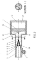
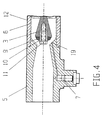
- This embodiment is the preferred embodiment of the invention. It is important to note that the poppet described in Figures 1, 2, 3, 4, 6, 9, 10 and 11 is the point of the invention.
- the addition of this poppet to the accumulator design permits control of the expelled fluid such that the fluid side pressure will not be below the gas pre-charge pressure.
- This valve sealing mechanism will allow the piston to travel to a position of pressure equilibrium and will prevent contact loads from being transferred to the vessel permitting the sealing prior to the piston achieving the fully stroked position, eliminating contact stress with the vessel.
- the return spring (6) will apply force to the valve mechanism to return it to an open position.
- the return spring (6) is attached to poppet (3) which when opened allows hydraulic flow into the liquid chamber (16) compressing the gas in the gas chamber (17) of the accumulator chamber (12). This hydraulic flow expands the bellows (8) moving the protruding center (18) of the rear wall of the piston (1) away from the contact pin (2) of the poppet (3) compressing the gas in the gas chamber (17).
- FIG. 2 An alternative embodiment of the invention is demonstrated in Figure 2 and Figure 3.
- bellows are replaced by the piston (1).
- the piston (1) acts as a separator between the liquid chamber (16) and the gas chamber (17) with the piston (1) flush with the interior walls of the accumulator housing (12), sealed by "O" ring (13).
- the principles and operation of the accumulator so designed is the same with the exception of the replacement for the bellows (8).
- Figure 2 shows the poppet seal, in the closed position, with the (9) seal and seal retainer (10) resting on the shoulders (19) of the seal valve to stop the fluid flow to the liquid chamber (16) when the pressure in the liquid chamber (16) is equal to the pressure in the gas chamber (17).
- Figure 4 is a cut away portion of the poppet (3) in its open position to allow fluid to flow into the liquid chamber (16) wherein the return spring (6) is acting in opposition to compression spring (4) pushing out the contact pin (2) to push out piston (1) to compress the gas in the gas chamber (17).
- seal retainer (10) and seal (9) on the poppet (3) held together by seal retainer screw (11) away and from the shoulder away and from the shoulders (19) of the seat valve (5) in the open position.
- the point of present invention is the introduction of the poppet valve design to seal the fluid chamber prior to the piston reaching the fully stroked position. This unique design prevents the piston from being subjected to the full pre-charge load during cycling.
- valve mechanism An additional benefit of this valve mechanism is the establishment of an equilibrium position with the spring loaded poppet valve design providing an integral pressure relief feature due to pressure changes associated with temperature changes in the system.
Landscapes
- Engineering & Computer Science (AREA)
- General Engineering & Computer Science (AREA)
- Mechanical Engineering (AREA)
- Physics & Mathematics (AREA)
- Fluid Mechanics (AREA)
- Supply Devices, Intensifiers, Converters, And Telemotors (AREA)
- Reciprocating, Oscillating Or Vibrating Motors (AREA)
Claims (2)
- Un accumulateur comprenant:l'accumulateur étant caractérisé en ce que :a) un boítier creux ;b) un soufflet (8) placé à l'intérieur du boítier, ledit soufflet comprenant un corps de soufflet ayant une première extrémité (14) et une deuxième extrémité (15), ladite première extrémité (14) étant fixée au boítier et ladite deuxième extrémité (15) étant laissée se déplacer dans la direction axiale du boítier ;c) le soufflet (8) étant fixé à un piston (1) afin de fermer la deuxième extrémité (15) du corps de soufflet ;d) une chambre à liquide (16) définie par une face intérieure dudit corps de soufflet et une paroi arrière dudit piston (1) et remplie par un liquide, ladite paroi arrière du piston (1) ayant un centre (18) en saillie ;e) une chambre à gaz (17), définie par une face extérieure du corps de soufflet et ledit piston (1) et remplie d'un gaz comprimé ;f) un siège de tube (5) ayant un orifice d'écoulement de liquide mis en communication avec la chambre de liquide (16) et permettant à du liquide présent dans la chambre à liquide de passer, lorsque le soufflet (8) est comprimé ou expansé, et un premier jeu d'épaulements à une extrémité avant dudit siège de tube (5) ; etg) un mécanisme d'auto-étanchéité (2, 3, 4, 6, 9, 10 et 11) ;le mécanisme à auto-étanchéité (2, 3, 4, 6, 9, 10 et 11) comprend un opercule (3) en forme de flèche, ayant une tige, un téton de contact (2) et une extrémité de queue extérieure en une position axiale opposée à celle du téton de contact (2), ledit téton de contact (2) étant logé dans la tige et relié à un ressort de compression (4) intérieur et étant directement opposé audit centre arrière en saillie (18) dudit piston (1), ladite extrémité de queue extérieure ayant un deuxième jeu d'épaulements agencé pour venir en contact avec le premier jeu d'épaulements à l'extrémité avant du siège de tube (5), le deuxième jeu d'épaulements comprenant un élément de retenue de joint d'étanchéité (10) et un joint d'étanchéité (9), le joint d'étanchéité étant agencé pour se monter sur ledit premier jeu d'épaulements (19), lorsque le gaz présent dans la chambre à gaz (17) force le piston à se déplacer axialement pour venir en contact avec et déplacer le téton de contact (2) dans une direction de compression du ressort de compression (4) intérieur, ledit déplacement du piston (1) provoquant la déformation du soufflet dans sa direction axiale, à un degré prédéterminé ;la compression du ressort de compression intérieur (4) ayant comme effet de comprimer un ressort extérieur (6) fixé sur l'extrémité de queue extérieure de l'opercule (3) en une position axiale opposée à celle dudit téton de contact (2), et ledit déplacement du piston (1) ayant comme effet de pousser l'extrémité de queue extérieure pour se monter sur et isoler de façon étanche le siège de tube (5) pour définir une position fermée du mécanisme d'auto-étanchéité à laquelle du liquide cesse de s'écouler depuis la chambre à liquide (16) ;ledit le mécanisme d'auto-étanchéité, à son état fermé, confinant une partie du liquide présent dans la chambre à liquide (16) à une région intérieure au soufflet (8) ;ledit ressort extérieur (6) étant agencé pour agir en tant que ressort de rappel en opposition à l'action dudit ressort intérieur (4) et pour permettre au dispositif d'étanchéité du siège de tube (5) d'être ouvert sous l'effet de la pression hydraulique provenant du liquide, de manière que le soufflet (8) s'expanse et pousse le piston (1) en direction axiale pour comprimer le gaz dans ladite chambre à gaz (17),
- Un accumulateur comprenant :l'accumulateur étant caractérisé en ce que :a) un boítier creux ;b) un piston (1) placé à l'intérieur du boítier, ledit piston (1) étant en alignement avec la paroi intérieure dudit boítier et isolé de façon étanche par un élément torique (13) ;c) ledit piston (1) séparant une chambre à gaz (17) d'une chambre à liquide (16);d) ladite chambre à liquide (16) étant définie par la paroi intérieure du boítier et une paroi arrière dudit piston (1), ladite paroi arrière dudit piston ayant un centre (18) en saillie ;e) ladite chambre à gaz (17) étant définie par la paroi intérieure dudit boítier et un côté avant dudit piston (1) et chargée par du gaz comprimé;f) un siège de tube (5) ayant un orifice d'écoulement de liquide mis en communication avec la chambre de liquide (16) et permettant à du liquide de pénétrer et de sortir de la chambre de liquide (16), ledit siège de tube (5) ayant un premier jeu d'épaulements (19) à une extrémité avant dudit siège de tube (5), etg) un mécanisme d'auto-étanchéité (2, 3, 4, 6, 9, 10 et 11) ;le mécanisme à auto-étanchéité (2, 3, 4, 6, 9, 10 et 11) comprend un opercule (3) en forme de flèche ayant une tige, un téton de contact (2) et une extrémité de queue extérieure en une position axiale opposée à celle du téton de contact (2), ledit téton de contact (2) étant logé dans la tige et relié à un ressort de compression (4) intérieur et étant directement opposé audit centre arrière en saillie (18) dudit piston (1), ladite extrémité de queue extérieure ayant un deuxième jeu d'épaulements agencés pour venir en contact avec le premier jeu d'épaulements à l'extrémité avant du siège de tube (5), le deuxième jeu d'épaulements comprenant un élément de retenue de joint d'étanchéité (10) et un joint d'étanchéité (9), le joint d'étanchéité étant agencé pour se monter sur ledit premier jeu d'épaulements (19), lorsque le gaz présent dans la chambre à gaz (17) force ledit piston à se déplacer axialement pour venir en contact avec et déplacer le téton de contact (2) dans une direction de compression du ressort de compression (4) intérieur, ledit déplacement du piston (1) se faisant à un degré prédéterminé ;la compression du ressort de compression intérieur (4) ayant comme effet de comprimer un ressort extérieur (6), fixé sur l'extrémité de queue extérieure de l'opercule (3), en une position axiale opposée à celle dudit téton de contact (2), et ledit déplacement du piston (1) ayant comme effet de pousser l'extrémité de queue extérieure pour se monter sur et isoler de façon étanche le siège de tube (5) pour définir une position fermée du mécanisme d'auto-étanchéité, à laquelle l'écoulement du liquide depuis la chambre de liquide (16) est coupé ;ledit le mécanisme d'auto-étanchéité, à son état fermé, confinant une partie du liquide présent dans la chambre à liquide (16) à une région intérieure à la chambre de liquide (16), entre le premier jeu d'épaulements (19) et la paroi arrière du piston (1) ;ledit ressort extérieur (6) étant agencé pour agir en tant que ressort de rappel en opposition à l'action dudit ressort intérieur (4) et pour permettre au joint d'étanchéité du siège de tube (5) d'être ouvert sous l'effet de la pression hydraulique provenant du liquide, de manière que le piston (1) est poussé en direction axiale afin de comprimer le gaz présent dans ladite chambre à gaz (17).
Applications Claiming Priority (3)
| Application Number | Priority Date | Filing Date | Title |
|---|---|---|---|
| US660676 | 1996-06-05 | ||
| US08/660,676 US5638868A (en) | 1996-06-05 | 1996-06-05 | Accumulator |
| PCT/US1997/009677 WO1997046823A1 (fr) | 1996-06-05 | 1997-06-04 | Nouvel accumulateur |
Publications (3)
| Publication Number | Publication Date |
|---|---|
| EP0901595A1 EP0901595A1 (fr) | 1999-03-17 |
| EP0901595A4 EP0901595A4 (fr) | 1999-08-18 |
| EP0901595B1 true EP0901595B1 (fr) | 2003-05-28 |
Family
ID=24650515
Family Applications (1)
| Application Number | Title | Priority Date | Filing Date |
|---|---|---|---|
| EP97929792A Expired - Lifetime EP0901595B1 (fr) | 1996-06-05 | 1997-06-04 | Nouvel accumulateur |
Country Status (9)
| Country | Link |
|---|---|
| US (1) | US5638868A (fr) |
| EP (1) | EP0901595B1 (fr) |
| JP (1) | JP2000511996A (fr) |
| AT (1) | ATE241774T1 (fr) |
| DE (1) | DE69722400T2 (fr) |
| DK (1) | DK0901595T3 (fr) |
| ES (1) | ES2200181T3 (fr) |
| PT (1) | PT901595E (fr) |
| WO (1) | WO1997046823A1 (fr) |
Cited By (1)
| Publication number | Priority date | Publication date | Assignee | Title |
|---|---|---|---|---|
| CN103758776A (zh) * | 2014-01-28 | 2014-04-30 | 长沙中粮机械有限公司 | 风量控制装置及离心风机 |
Families Citing this family (25)
| Publication number | Priority date | Publication date | Assignee | Title |
|---|---|---|---|---|
| US7614568B2 (en) * | 2000-08-24 | 2009-11-10 | Microlin, Llc | Device employing gas generating cell for facilitating controlled release of fluid into ambient environment |
| NL1011596C1 (nl) * | 1998-06-30 | 2000-01-04 | Watts Ocean B V | Debietbegrenzer. |
| EP1133641B1 (fr) * | 1998-11-25 | 2004-06-09 | Continental Teves AG & Co. oHG | Accumulateur d'agent de pression |
| DE19924807A1 (de) * | 1999-05-29 | 2000-12-07 | Hydac Technology Gmbh | Hydropneumatischer Druckspeicher |
| US6089274A (en) * | 1999-08-11 | 2000-07-18 | Fan; Jui-Hua | I-type counterflow absorber |
| DE10003648A1 (de) * | 2000-01-29 | 2001-08-09 | Hydac Technology Gmbh | Hydropneumatischer Druckspeicher |
| DE10009865B4 (de) * | 2000-03-01 | 2007-12-13 | Hydac Technology Gmbh | Hydropneumatischer Druckspeicher, insbesondere Pulsationsdämpfer |
| US6412476B1 (en) * | 2000-08-02 | 2002-07-02 | Ford Global Tech., Inc. | Fuel system |
| CA2419720A1 (fr) * | 2000-08-28 | 2002-03-07 | John Paul Mckelvey | Dispositif de tensionnement gonflable |
| US6405760B1 (en) | 2001-02-05 | 2002-06-18 | Perkinelmer, Inc. | Accumulator |
| BE1014807A5 (nl) * | 2002-04-30 | 2004-04-06 | Groep Stevens International Na | Fluidumaccumulator en werkwijze voor het vervaardigen ervan. |
| JP3906915B2 (ja) * | 2002-07-15 | 2007-04-18 | 株式会社アドヴィックス | 液圧回路 |
| JP3867648B2 (ja) * | 2002-09-19 | 2007-01-10 | 株式会社アドヴィックス | ベローズ式液圧アキュムレータ |
| DE10305000B4 (de) * | 2003-02-07 | 2005-02-03 | Carl Freudenberg Kg | Metallbalgdruckspeicher für hydraulische Systeme |
| DE10305001B9 (de) * | 2003-02-07 | 2013-09-12 | Carl Freudenberg Kg | Metallbalgdruckspeicher für hydraulische Systeme |
| US20050155658A1 (en) * | 2004-01-20 | 2005-07-21 | White Andrew J. | Hermetically sealed pressure balanced accumulator |
| DE102004004341A1 (de) * | 2004-01-29 | 2005-08-18 | Hydac Technology Gmbh | Druckspeicher, insbesondere Pulsationsdämpfer |
| JP4641387B2 (ja) * | 2004-06-01 | 2011-03-02 | 日産自動車株式会社 | 流体継手 |
| US8113390B2 (en) * | 2007-04-18 | 2012-02-14 | Microlin, Llc | Gas generation dispenser apparatus and method for on-demand fluid delivery |
| CN101809294B (zh) * | 2007-10-10 | 2013-06-26 | 伊格尔工业股份有限公司 | 蓄能器 |
| US20090315266A1 (en) * | 2008-06-19 | 2009-12-24 | Baker Hughes Incorporated | Extrusion-Resistant Nose Seal |
| US20100176214A1 (en) * | 2009-01-13 | 2010-07-15 | Joshi Ashok V | Greeting card fragrance delivery system |
| EP2714102B1 (fr) | 2011-06-03 | 2018-10-10 | Microlin, LLC | Dispositif pour délivrance de liquides volatils à un environnement gazeux |
| FR3020417A1 (fr) * | 2014-04-23 | 2015-10-30 | Inergy Automotive Systems Res | Accumulateur de pression |
| CN111517004B (zh) * | 2019-02-01 | 2022-05-06 | 中石化广州工程有限公司 | 储油罐进油装置 |
Family Cites Families (14)
| Publication number | Priority date | Publication date | Assignee | Title |
|---|---|---|---|---|
| US2745357A (en) * | 1951-10-22 | 1956-05-15 | Northrop Aircraft Inc | Pressurized hydraulic reservoir |
| FR1391050A (fr) * | 1964-01-17 | 1965-03-05 | Rech Etudes Production Sarl | Accumulateur hydropneumatique de sécurité, applicable notamment aux circuits hydrauliques des aérodynes |
| DE2634945A1 (de) * | 1976-08-04 | 1978-02-09 | Bosch Gmbh Robert | Ventil fuer einen druckspeicher |
| JPS59120524A (ja) * | 1982-12-28 | 1984-07-12 | Isuzu Motors Ltd | 電子制御式変速機の変速操作方法 |
| US4461322A (en) * | 1983-05-06 | 1984-07-24 | Mills Carl R | Accumulator with piston-poppet seal assembly |
| GB2156435B (en) * | 1984-03-30 | 1987-09-03 | Bosch Gmbh Robert | Pressure medium accumulator |
| US4610369A (en) * | 1985-10-07 | 1986-09-09 | Mercier Jacques H | Pressure vessel |
| FR2602283B1 (fr) * | 1986-08-04 | 1988-10-21 | Peugeot | Procede de fabrication d'un accumulateur hydropneumatique |
| US4691739A (en) * | 1986-09-02 | 1987-09-08 | United Aircraft Products, Inc. | Bootstrap reservoir |
| US4959958A (en) * | 1987-12-30 | 1990-10-02 | Honda Giken Kogyo Kabushiki Kaisha | Hydraulic pressure system |
| JPH02266101A (ja) * | 1989-04-05 | 1990-10-30 | Nhk Spring Co Ltd | アキュムレータ |
| FR2649451B1 (fr) * | 1989-07-05 | 1991-10-25 | Europ Propulsion | Accumulateur de liquide sous haute pression a niveau de liquide regule |
| US5009066A (en) * | 1989-11-13 | 1991-04-23 | General Motors Corporation | Automotive power steering system |
| DE4112920A1 (de) * | 1991-04-19 | 1992-10-22 | Teves Gmbh Alfred | Elektromagnetventil, insbesondere fuer schlupfgeregelte kraftfahrzeugbremsanlagen |
-
1996
- 1996-06-05 US US08/660,676 patent/US5638868A/en not_active Expired - Fee Related
-
1997
- 1997-06-04 DE DE69722400T patent/DE69722400T2/de not_active Expired - Lifetime
- 1997-06-04 PT PT97929792T patent/PT901595E/pt unknown
- 1997-06-04 WO PCT/US1997/009677 patent/WO1997046823A1/fr active IP Right Grant
- 1997-06-04 JP JP10500832A patent/JP2000511996A/ja active Pending
- 1997-06-04 AT AT97929792T patent/ATE241774T1/de active
- 1997-06-04 EP EP97929792A patent/EP0901595B1/fr not_active Expired - Lifetime
- 1997-06-04 ES ES97929792T patent/ES2200181T3/es not_active Expired - Lifetime
- 1997-06-04 DK DK97929792T patent/DK0901595T3/da active
Cited By (2)
| Publication number | Priority date | Publication date | Assignee | Title |
|---|---|---|---|---|
| CN103758776A (zh) * | 2014-01-28 | 2014-04-30 | 长沙中粮机械有限公司 | 风量控制装置及离心风机 |
| CN103758776B (zh) * | 2014-01-28 | 2015-11-18 | 长沙中粮机械有限公司 | 风量控制装置及离心风机 |
Also Published As
| Publication number | Publication date |
|---|---|
| DE69722400T2 (de) | 2004-04-08 |
| JP2000511996A (ja) | 2000-09-12 |
| ES2200181T3 (es) | 2004-03-01 |
| EP0901595A4 (fr) | 1999-08-18 |
| WO1997046823A1 (fr) | 1997-12-11 |
| EP0901595A1 (fr) | 1999-03-17 |
| DE69722400D1 (de) | 2003-07-03 |
| PT901595E (pt) | 2003-10-31 |
| ATE241774T1 (de) | 2003-06-15 |
| US5638868A (en) | 1997-06-17 |
| DK0901595T3 (da) | 2003-09-22 |
Similar Documents
| Publication | Publication Date | Title |
|---|---|---|
| EP0901595B1 (fr) | Nouvel accumulateur | |
| EP0391320B1 (fr) | Accumulateur | |
| CA1276654C (fr) | Amortisseur de chocs avec ressort de rappel a gaz comprime | |
| US4550899A (en) | Pneumatic spring | |
| US5682923A (en) | Accumulator having an internal elastomeric member | |
| CA2222799C (fr) | Ressort pneumatique | |
| CA1198033A (fr) | Accumulateur avec piston a clapet | |
| US4548389A (en) | Redundant high-pressure seal for fluid spring | |
| US4664362A (en) | Gas spring | |
| US4759260A (en) | Super reliable air-spring return air cylinder | |
| EP1358425B1 (fr) | Accumulateur pour liquides | |
| US4375181A (en) | Hydraulic cylinder extending in three force modes | |
| JPH01279127A (ja) | 非増加型気体バネ | |
| US5349894A (en) | Locking hydraulic actuator | |
| US2817361A (en) | Piston accumulator | |
| JPH02102901A (ja) | 空気油圧増圧式の圧力変換器の圧油充填法及びその方法を実施するための装置 | |
| US4470583A (en) | Hydro-pneumatic tensioning unit for endless track | |
| US2747370A (en) | Fluid pressure device | |
| US5116028A (en) | Pressure tube-piston device | |
| US4291718A (en) | Pressure valve | |
| US20040250866A1 (en) | Pressure medium reservoir | |
| EP0341021A2 (fr) | Amortisseur hydraulique | |
| EP0347921A3 (fr) | Ressort à fluide | |
| US6651547B2 (en) | Guide for the piston rod of a piston-cylinder assembly | |
| SU996768A1 (ru) | Пневмогидравлическа рессора |
Legal Events
| Date | Code | Title | Description |
|---|---|---|---|
| PUAI | Public reference made under article 153(3) epc to a published international application that has entered the european phase |
Free format text: ORIGINAL CODE: 0009012 |
|
| 17P | Request for examination filed |
Effective date: 19981230 |
|
| AK | Designated contracting states |
Kind code of ref document: A1 Designated state(s): AT BE CH DE DK ES FI FR GB GR IE IT LI LU MC NL PT SE |
|
| A4 | Supplementary search report drawn up and despatched |
Effective date: 19990705 |
|
| AK | Designated contracting states |
Kind code of ref document: A4 Designated state(s): AT BE CH DE DK ES FI FR GB GR IE IT LI LU MC NL PT SE |
|
| RIC1 | Information provided on ipc code assigned before grant |
Free format text: 6F 16L 55/04 A, 6F 15B 1/22 B |
|
| 17Q | First examination report despatched |
Effective date: 20010822 |
|
| GRAH | Despatch of communication of intention to grant a patent |
Free format text: ORIGINAL CODE: EPIDOS IGRA |
|
| GRAH | Despatch of communication of intention to grant a patent |
Free format text: ORIGINAL CODE: EPIDOS IGRA |
|
| GRAH | Despatch of communication of intention to grant a patent |
Free format text: ORIGINAL CODE: EPIDOS IGRA |
|
| GRAA | (expected) grant |
Free format text: ORIGINAL CODE: 0009210 |
|
| AK | Designated contracting states |
Designated state(s): AT BE CH DE DK ES FI FR GB GR IE IT LI LU MC NL PT SE |
|
| REG | Reference to a national code |
Ref country code: GB Ref legal event code: FG4D |
|
| REG | Reference to a national code |
Ref country code: CH Ref legal event code: EP |
|
| REG | Reference to a national code |
Ref country code: IE Ref legal event code: FG4D |
|
| REF | Corresponds to: |
Ref document number: 69722400 Country of ref document: DE Date of ref document: 20030703 Kind code of ref document: P |
|
| REG | Reference to a national code |
Ref country code: SE Ref legal event code: TRGR |
|
| REG | Reference to a national code |
Ref country code: DK Ref legal event code: T3 |
|
| REG | Reference to a national code |
Ref country code: GR Ref legal event code: EP Ref document number: 20030403398 Country of ref document: GR |
|
| REG | Reference to a national code |
Ref country code: CH Ref legal event code: NV Representative=s name: PATMED AG |
|
| REG | Reference to a national code |
Ref country code: ES Ref legal event code: FG2A Ref document number: 2200181 Country of ref document: ES Kind code of ref document: T3 |
|
| PLBE | No opposition filed within time limit |
Free format text: ORIGINAL CODE: 0009261 |
|
| STAA | Information on the status of an ep patent application or granted ep patent |
Free format text: STATUS: NO OPPOSITION FILED WITHIN TIME LIMIT |
|
| ET | Fr: translation filed | ||
| 26N | No opposition filed |
Effective date: 20040302 |
|
| PGFP | Annual fee paid to national office [announced via postgrant information from national office to epo] |
Ref country code: ES Payment date: 20120605 Year of fee payment: 16 |
|
| PGFP | Annual fee paid to national office [announced via postgrant information from national office to epo] |
Ref country code: AT Payment date: 20120411 Year of fee payment: 16 |
|
| PGFP | Annual fee paid to national office [announced via postgrant information from national office to epo] |
Ref country code: SE Payment date: 20130610 Year of fee payment: 17 Ref country code: GB Payment date: 20130523 Year of fee payment: 17 Ref country code: DE Payment date: 20130625 Year of fee payment: 17 Ref country code: MC Payment date: 20130528 Year of fee payment: 17 Ref country code: LU Payment date: 20130605 Year of fee payment: 17 Ref country code: DK Payment date: 20130606 Year of fee payment: 17 Ref country code: IE Payment date: 20130523 Year of fee payment: 17 |
|
| PGFP | Annual fee paid to national office [announced via postgrant information from national office to epo] |
Ref country code: PT Payment date: 20130523 Year of fee payment: 17 Ref country code: FI Payment date: 20130612 Year of fee payment: 17 Ref country code: GR Payment date: 20130524 Year of fee payment: 17 Ref country code: IT Payment date: 20130606 Year of fee payment: 17 Ref country code: NL Payment date: 20130617 Year of fee payment: 17 |
|
| PGFP | Annual fee paid to national office [announced via postgrant information from national office to epo] |
Ref country code: BE Payment date: 20130621 Year of fee payment: 17 |
|
| PGFP | Annual fee paid to national office [announced via postgrant information from national office to epo] |
Ref country code: CH Payment date: 20130926 Year of fee payment: 17 |
|
| PGFP | Annual fee paid to national office [announced via postgrant information from national office to epo] |
Ref country code: FR Payment date: 20130725 Year of fee payment: 17 |
|
| REG | Reference to a national code |
Ref country code: PT Ref legal event code: MM4A Free format text: LAPSE DUE TO NON-PAYMENT OF FEES Effective date: 20141204 |
|
| REG | Reference to a national code |
Ref country code: DE Ref legal event code: R119 Ref document number: 69722400 Country of ref document: DE |
|
| REG | Reference to a national code |
Ref country code: DK Ref legal event code: EBP Effective date: 20140630 |
|
| REG | Reference to a national code |
Ref country code: NL Ref legal event code: V1 Effective date: 20150101 |
|
| PG25 | Lapsed in a contracting state [announced via postgrant information from national office to epo] |
Ref country code: LU Free format text: LAPSE BECAUSE OF NON-PAYMENT OF DUE FEES Effective date: 20140604 Ref country code: FI Free format text: LAPSE BECAUSE OF NON-PAYMENT OF DUE FEES Effective date: 20140604 Ref country code: PT Free format text: LAPSE BECAUSE OF NON-PAYMENT OF DUE FEES Effective date: 20141204 Ref country code: SE Free format text: LAPSE BECAUSE OF NON-PAYMENT OF DUE FEES Effective date: 20140605 Ref country code: MC Free format text: LAPSE BECAUSE OF NON-PAYMENT OF DUE FEES Effective date: 20140630 |
|
| REG | Reference to a national code |
Ref country code: CH Ref legal event code: PL |
|
| REG | Reference to a national code |
Ref country code: SE Ref legal event code: EUG |
|
| REG | Reference to a national code |
Ref country code: AT Ref legal event code: MM01 Ref document number: 241774 Country of ref document: AT Kind code of ref document: T Effective date: 20140604 |
|
| GBPC | Gb: european patent ceased through non-payment of renewal fee |
Effective date: 20140604 |
|
| REG | Reference to a national code |
Ref country code: GR Ref legal event code: ML Ref document number: 20030403398 Country of ref document: GR Effective date: 20150105 |
|
| REG | Reference to a national code |
Ref country code: IE Ref legal event code: MM4A |
|
| REG | Reference to a national code |
Ref country code: FR Ref legal event code: ST Effective date: 20150227 |
|
| PG25 | Lapsed in a contracting state [announced via postgrant information from national office to epo] |
Ref country code: NL Free format text: LAPSE BECAUSE OF NON-PAYMENT OF DUE FEES Effective date: 20150101 |
|
| REG | Reference to a national code |
Ref country code: DE Ref legal event code: R119 Ref document number: 69722400 Country of ref document: DE Effective date: 20150101 |
|
| PG25 | Lapsed in a contracting state [announced via postgrant information from national office to epo] |
Ref country code: CH Free format text: LAPSE BECAUSE OF NON-PAYMENT OF DUE FEES Effective date: 20140630 Ref country code: IE Free format text: LAPSE BECAUSE OF NON-PAYMENT OF DUE FEES Effective date: 20140604 Ref country code: IT Free format text: LAPSE BECAUSE OF NON-PAYMENT OF DUE FEES Effective date: 20140604 Ref country code: LI Free format text: LAPSE BECAUSE OF NON-PAYMENT OF DUE FEES Effective date: 20140630 Ref country code: DE Free format text: LAPSE BECAUSE OF NON-PAYMENT OF DUE FEES Effective date: 20150101 |
|
| PG25 | Lapsed in a contracting state [announced via postgrant information from national office to epo] |
Ref country code: AT Free format text: LAPSE BECAUSE OF NON-PAYMENT OF DUE FEES Effective date: 20140604 Ref country code: GB Free format text: LAPSE BECAUSE OF NON-PAYMENT OF DUE FEES Effective date: 20140604 Ref country code: FR Free format text: LAPSE BECAUSE OF NON-PAYMENT OF DUE FEES Effective date: 20140630 Ref country code: GR Free format text: LAPSE BECAUSE OF NON-PAYMENT OF DUE FEES Effective date: 20150105 |
|
| REG | Reference to a national code |
Ref country code: ES Ref legal event code: FD2A Effective date: 20150729 |
|
| PG25 | Lapsed in a contracting state [announced via postgrant information from national office to epo] |
Ref country code: DK Free format text: LAPSE BECAUSE OF NON-PAYMENT OF DUE FEES Effective date: 20140630 |
|
| PG25 | Lapsed in a contracting state [announced via postgrant information from national office to epo] |
Ref country code: ES Free format text: LAPSE BECAUSE OF NON-PAYMENT OF DUE FEES Effective date: 20140605 |
|
| PG25 | Lapsed in a contracting state [announced via postgrant information from national office to epo] |
Ref country code: BE Free format text: LAPSE BECAUSE OF NON-PAYMENT OF DUE FEES Effective date: 20140630 |