EP0901445B1 - Hydraulischer federspanner - Google Patents
Hydraulischer federspanner Download PDFInfo
- Publication number
- EP0901445B1 EP0901445B1 EP97926079A EP97926079A EP0901445B1 EP 0901445 B1 EP0901445 B1 EP 0901445B1 EP 97926079 A EP97926079 A EP 97926079A EP 97926079 A EP97926079 A EP 97926079A EP 0901445 B1 EP0901445 B1 EP 0901445B1
- Authority
- EP
- European Patent Office
- Prior art keywords
- tubular part
- sleeve
- tubular
- piston
- compressor
- Prior art date
- Legal status (The legal status is an assumption and is not a legal conclusion. Google has not performed a legal analysis and makes no representation as to the accuracy of the status listed.)
- Expired - Lifetime
Links
Images

Classifications
-
- B—PERFORMING OPERATIONS; TRANSPORTING
- B62—LAND VEHICLES FOR TRAVELLING OTHERWISE THAN ON RAILS
- B62D—MOTOR VEHICLES; TRAILERS
- B62D65/00—Designing, manufacturing, e.g. assembling, facilitating disassembly, or structurally modifying motor vehicles or trailers, not otherwise provided for
- B62D65/02—Joining sub-units or components to, or positioning sub-units or components with respect to, body shell or other sub-units or components
- B62D65/12—Joining sub-units or components to, or positioning sub-units or components with respect to, body shell or other sub-units or components the sub-units or components being suspensions, brakes or wheel units
-
- B—PERFORMING OPERATIONS; TRANSPORTING
- B25—HAND TOOLS; PORTABLE POWER-DRIVEN TOOLS; MANIPULATORS
- B25B—TOOLS OR BENCH DEVICES NOT OTHERWISE PROVIDED FOR, FOR FASTENING, CONNECTING, DISENGAGING OR HOLDING
- B25B27/00—Hand tools, specially adapted for fitting together or separating parts or objects whether or not involving some deformation, not otherwise provided for
- B25B27/14—Hand tools, specially adapted for fitting together or separating parts or objects whether or not involving some deformation, not otherwise provided for for assembling objects other than by press fit or detaching same
- B25B27/30—Hand tools, specially adapted for fitting together or separating parts or objects whether or not involving some deformation, not otherwise provided for for assembling objects other than by press fit or detaching same positioning or withdrawing springs, e.g. coil or leaf springs
- B25B27/302—Hand tools, specially adapted for fitting together or separating parts or objects whether or not involving some deformation, not otherwise provided for for assembling objects other than by press fit or detaching same positioning or withdrawing springs, e.g. coil or leaf springs coil springs other than torsion coil springs
- B25B27/304—Hand tools, specially adapted for fitting together or separating parts or objects whether or not involving some deformation, not otherwise provided for for assembling objects other than by press fit or detaching same positioning or withdrawing springs, e.g. coil or leaf springs coil springs other than torsion coil springs by compressing coil springs
-
- Y—GENERAL TAGGING OF NEW TECHNOLOGICAL DEVELOPMENTS; GENERAL TAGGING OF CROSS-SECTIONAL TECHNOLOGIES SPANNING OVER SEVERAL SECTIONS OF THE IPC; TECHNICAL SUBJECTS COVERED BY FORMER USPC CROSS-REFERENCE ART COLLECTIONS [XRACs] AND DIGESTS
- Y10—TECHNICAL SUBJECTS COVERED BY FORMER USPC
- Y10T—TECHNICAL SUBJECTS COVERED BY FORMER US CLASSIFICATION
- Y10T29/00—Metal working
- Y10T29/53—Means to assemble or disassemble
- Y10T29/53552—Valve applying or removing
- Y10T29/53561—Engine valve spring compressor [only]
-
- Y—GENERAL TAGGING OF NEW TECHNOLOGICAL DEVELOPMENTS; GENERAL TAGGING OF CROSS-SECTIONAL TECHNOLOGIES SPANNING OVER SEVERAL SECTIONS OF THE IPC; TECHNICAL SUBJECTS COVERED BY FORMER USPC CROSS-REFERENCE ART COLLECTIONS [XRACs] AND DIGESTS
- Y10—TECHNICAL SUBJECTS COVERED BY FORMER USPC
- Y10T—TECHNICAL SUBJECTS COVERED BY FORMER US CLASSIFICATION
- Y10T29/00—Metal working
- Y10T29/53—Means to assemble or disassemble
- Y10T29/53613—Spring applier or remover
- Y10T29/53617—Transmission spring
-
- Y—GENERAL TAGGING OF NEW TECHNOLOGICAL DEVELOPMENTS; GENERAL TAGGING OF CROSS-SECTIONAL TECHNOLOGIES SPANNING OVER SEVERAL SECTIONS OF THE IPC; TECHNICAL SUBJECTS COVERED BY FORMER USPC CROSS-REFERENCE ART COLLECTIONS [XRACs] AND DIGESTS
- Y10—TECHNICAL SUBJECTS COVERED BY FORMER USPC
- Y10T—TECHNICAL SUBJECTS COVERED BY FORMER US CLASSIFICATION
- Y10T29/00—Metal working
- Y10T29/53—Means to assemble or disassemble
- Y10T29/53613—Spring applier or remover
- Y10T29/53622—Helical spring
Definitions
- the cylinder used is a screw jack and the body can be in two telescopic parts.
- the largest part of the diameter its center a screw immobilized in translation with respect to it while the less important diameter part carries a nut, this part being locked in rotation by relative to the largest diameter portion.
- the compressor spring has two cylinders side by side each having a fixed piston and a movable cylinder, a cup being secured to the movable cylinder of each cylinder while a other cup is carried by a plate which is fixed with the piston and which is integral with a guide tube for each of the cylinders movable relative to the piston.
- the two cylinders side by side is required share to allow the development of a force of sufficient compression, the device being pneumatic, and secondly to ensure rectilinear guidance of the cup movable relative to the fixed cup in order to resist the tendency which the spring would have to make turn one cup relative to the other.
- the efforts involved are such that, to resist buckling, the cylinder of each pneumatic cylinder, must remain very largely inside the corresponding guide tube when the device is at its maximum extension. he this results in an axial bulk of the device for a given race. All these causes of congestion important that this device is not suitable in particular motor vehicle bodywork interventions at when changing or repairing shock absorbers.
- the present invention relates to a fluid cylinder under pressure, and in particular a hydraulic fluid cylinder, which allows using a working pressure of the order of a few hundred bars, to have a small diameter device (of the order of 60 mm).
- this device is designed so as to present the minimum longitudinal dimensions for a stroke of compression given.
- the invention therefore relates to a hydraulic spring compressor having a body formed by a first tubular piece closed at one of its ends by a bottom in which is implanted the end of a hollow rod extending axially to the interior of the first tubular part and the other of which end is shaped like a piston, with a second piece tubular with one end closed by a crossed bottom by the hollow rod and mounted with sealed sliding on the rod and piston, defining a chamber between them variable volume in permanent communication with the volume inside the hollow rod, the first tubular part having on its outer surface at its end opposite the bottom, attachment means worn for a compression cup, the second tubular part and that having on its outer surface at its end opposite to its bottom, means of attachment for a second compression cup.
- the hollow rod is of length greater than that of the first tubular parts so its piston-like end is located beyond the attachment means carried by the first tubular part, the closed end of the second part tubular is located outside the attachment means of the first tubular part when the volume chamber variable is at its minimum volume, a connecting sleeve is slidably mounted between the first and the second tubular part respectively on the internal surfaces and external of these and, a set of groove and key is interposed between the second part and the sleeve to guide their respective longitudinal sliding and form shoulders coming into contact with each other to drive the sleeve axially through the second part when the variable volume chamber has exceeded one determined longitudinal dimension.
- the moving part of the compressor carrying the movable cup can take a first position in which this movable cup is adjacent to the cup carried by the compressor body, the moving part with the exception of the attachment means then being completely housed inside this body, and a second position in which the movable cup is moved away from the cup carried by the compressor body, the part carrying this movable cup being completely outside the compressor body.
- the mutual guidance of the telescopic parts and the buckling resistance of the compressor are provided by the sleeve interposed between the moving part and the body this one.
- the sleeve or the first tubular part has a longitudinal groove in which is housed a radial finger carried by the first piece or sleeve, respectively.
- the bottom of the second tubular part crossed by the rod is formed by a nut screwed internally at the end of this second part and having a support flange on an end face of this part in which opens a longitudinal groove formed on the surface outside of the second part, said flange constituting the aforementioned shoulder for driving a key fixed bearing by the sleeve and slidably mounted in the groove.
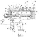
- the hydraulic spring compressor has a body here in three telescopic parts.
- a first part is formed by a tubular section 1 closed at one of its ends by a bottom and carries to its other end of means 2 known per se for attachment a jaw or compression cup spring symbolized by the dashed line 3.
- a sleeve 4 is slidably mounted inside this tubular part 1. He wears a key 5 which stops in rotation the sleeve 4 relative to the tubular part 1 by cooperating with a groove key 6 made in the inner cylindrical surface from part 1.
- the body Inside this intermediate sleeve 4, the body has a second tubular part 7 smaller diameter which is slidably mounted in the sleeve 4 and stopped relative to the latter by means of a key 8.
- This part 7 is of such length that it has a end held outside the tubular part outer 1, this outer end being equipped with means 9 known in themselves for the attachment of a second jaw or spring compression cup symbolized by the dashed line 10.
- the internal tubular part 7 forms the cylinder a jack whose rod 11 located in the bottom of the tubular part 1, door at its end opposite to that of its attachment to the bottom la, a piston 12 on which is able to slide the cylinder 7 tightly.
- the tubular part 7 is closed at its internal end at the part 1 by a bottom 7a crossed by the rod 11 so waterproof.
- the rod 11, the piston 12 and the cylinder 7 define between them a chamber 13 of variable volume which can be connected via a conduit 14 provided inside the rod 11 opening just under the piston 12, either to a source of pressurized fluid 15, or to a liquid return tank 16. Selection of communications is provided by a monostable distributor 17 whose stable position connects the chamber 13 with the recovery tank 16 through a restriction 18.
- the supply of the chamber 13 is effected by an action on the dispenser drawer 17 by means of a button operation 19 acting against a return spring 20.
- a button operation 19 acting against a return spring 20.
- the spring relaxation is then obtained by reopening the valve 23 and having released the distributor 17 so well that the fluid contained in the chamber 13 is expelled from this one through the conduit 14 under the effect of the action of the spring on the jaws 3 and 10 which tend to extend the compressor body, the speed of this expansion being limited by the presence of restriction 18 on the channel fluid exhaust.
- the maximum body extension of cylinder is obtained when the wall 7a reaches the vicinity of piston 12, without masking the outlet of the conduit 14 into chamber 13.
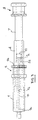
- FIG 2 which is an axial sectional view an industrial production of the hydraulic compressor according to the invention, we find some of the elements already described with the same references.
- the compressor is shown retracted.
- the piston 12 is housed inside the part la more extreme of the second tubular part 7, that is to say the one near its end equipped with means 9 for attaching the cup.
- Piston 12 is so thus very largely protruding from the end of the outer tubular body 1 which ends in the side 1b on which rest when the compressor is retracted means 9 for attaching the cup worn by the sliding part 7.
- the part tubular 7 therefore comprises the bottom 7a traversed by the rod 11.
- This bottom 7a is in fact produced by a nut screwed to inside the end of part 7 and bearing on its end face 7b by means of a flange 24.
- Sleeve 4 has an outer groove 25 limited by one end 25a of the innermost side of the compressor while this groove 25 opens freely at the other end of the sleeve 7.
- the tubular part 1 has a key 26 which is simply housed in a radial opening formed in the piece 1 and which has a bar projecting from the inner surface of this part 1 so as to penetrate in the groove 25.
- tubular part 7 is provided with an outer keyway 27 which extends over the entire part of room 7 not covered by the attachment means 9 and which opens onto the face 7b of this room.
- the flange 24 of the nut 23 forming the bottom 7a of the part 7 does it constitute a shoulder limiting the groove 27.
- a key 28 makes protrudes inside the sleeve 4 and is held in it sleeve by fitting into a lateral opening provided at this effect.
- the extension of the spring compressor consists of purge room 13. When it comes to setting up the compressor on a spring to be compressed, this extension is done by hand. When the flange 24 abuts against the key 28, the sleeve 4 is driven by the part 7. This sleeve partially exits the tubular part exterior 1 as shown in Figure 3 until the bottom 7a of the part 7 comes into contact piston 12.
- part 7 is located completely outside of room 1 and the connection between the two is provided by the sleeve 4 in which the part 7 remains largely embedded due to the position of the key 28, this sleeve itself largely remaining engaged inside the room 1.
- the role of the end 25a of the stop 25 is to come into contact with the key 26 to avoid a complete exit of the sleeve 4 from the part 1 if, inadvertently, the plug 24 forming the bottom 7a of the chamber 13 came to separate from the tube 7.
- the forces of traction are supported by the rod 11 while the buckling forces are absorbed by the parts tubular 7, 4 and 1.
Landscapes
- Engineering & Computer Science (AREA)
- Mechanical Engineering (AREA)
- Manufacturing & Machinery (AREA)
- Chemical & Material Sciences (AREA)
- Combustion & Propulsion (AREA)
- Transportation (AREA)
- Compressor (AREA)
- Vehicle Body Suspensions (AREA)
- Devices For Conveying Motion By Means Of Endless Flexible Members (AREA)
- Lining Or Joining Of Plastics Or The Like (AREA)
- Fluid-Damping Devices (AREA)
Claims (3)
- Hydraulischer Federspanner mit einem Gehäuse, das aus einem ersten rohrförmigen Teil (1) gebildet ist, das an einem seiner Enden von einem Boden (1a) geschlossen wird, in den das Ende einer Hohlstange (11) eingesetzt wird, die sich axial im Inneren des ersten rohrförmigen Teiles (1) erstreckt und deren anderes Ende als Kolben (12) ausgebildet ist, sowie aus einem zweiten rohrförmigen Teil (7), das ein Ende hat, das von einem von der Hohlstange (11) durchsetzten Boden (7a) geschlossen wird, und auf der Stange (11) und dem Kolben (12) abgedichtet verschiebbar ist, wobei das zweite rohrförmige Teil, die Stange und der Kolben miteinander eine Kammer (13) mit veränderlichem Volumen begrenzen, die in ständiger Verbindung mit dem Innenvolumen (14) der Hohlstange (11) steht, wobei das erste rohrförmige Teil (1) auf seiner Außenseite an seinem dem Boden (1a) entgegengesetzten Ende Befestigungsmittel (2) für einen Spannfederteller (3) hat, wobei das zweite rohrförmige Teil (7) auf seiner Außenseite an seinem dem Boden (7a) entgegengesetzten Ende Befestigungsmittel (9) für einen Spannfederteller (10) hat, und wobei die Hohlstange (11) eine Länge hat, die über der des ersten rohrförmigen Teiles (1) liegt, so daß sich ihr kolbenförmiges Ende (12) jenseits der Befestigungsmittel (2) befindet, die von dem ersten rohrförmigen Teil (1) getragen werden, dadurch gekennzeichnet, daß sich das geschlossene Ende (7a) des zweiten rohrförmigen Teiles (7) außerhalb der Befestigungsmittel (2) des ersten rohrförmigen Teiles (1) befindet, wenn die Kammer (13) mit veränderlichem Volumen ihr Minimalvolumen hat, daß eine Verbindungshülse (4) zwischen der Innenfläche des ersten rohrförmigen Teiles (1) und der Außenfläche des zweiten rohrförmigen Teiles (7) verschiebbar geführt ist und daß eine Einheit aus Nut und Keil (24, 27, 28) zwischen dem zweiten Teil (7) und der Hülse (4) angeordnet ist, um deren jeweilige Längsverschiebung zu führen und um Schultern zu bilden, die miteinander in Kontakt kommen, um die Hülse (4) axial durch das zweite Teil (7) mitzunehmen, wenn die Kammer (13) mit veränderlichem Volumen ein vorgegebenes Längsmaß überschritten hat.
- Federspanner nach Anspruch 1, dadurch gekennzeichnet, daß die Hülse (4) oder das erste Teil (1) eine Längsnut (25) hat, in der ein von dem ersten Teil (1) bzw. der Hülse (4) getragener radialer Zapfen (26) angeordnet ist.
- Federspanner nach Anspruch 1, dadurch gekennzeichnet, daß der Boden (7a) des von der Stange (11) durchsetzten, zweiten rohrförmigen Teiles von einer Mutter gebildet ist, die in das Ende dieses zweiten Teiles (7) eingeschraubt ist und einen Bund (24) zur Anlage an einer Endfläche (7b) dieses Teiles hat, in die eine Längsnut (27) mündet, die außen in dem zweiten rohrförmigen Teil (7) ausgebildet ist, wobei der Bund (24) die Schulter zur obengenannten Mitnahme eines radialen Keiles (28) bildet, der von der Hülse (4) ortsfest getragen wird und in der Nut (27) verschiebbar ist.
Applications Claiming Priority (3)
| Application Number | Priority Date | Filing Date | Title |
|---|---|---|---|
| FR9606805A FR2749363A1 (fr) | 1996-06-03 | 1996-06-03 | Compresseur de ressort a fluide sous pression |
| FR9606805 | 1996-06-03 | ||
| PCT/FR1997/000963 WO1997046442A1 (fr) | 1996-06-03 | 1997-06-03 | Compresseur hydraulique de ressort |
Publications (2)
| Publication Number | Publication Date |
|---|---|
| EP0901445A1 EP0901445A1 (de) | 1999-03-17 |
| EP0901445B1 true EP0901445B1 (de) | 2001-03-28 |
Family
ID=9492652
Family Applications (1)
| Application Number | Title | Priority Date | Filing Date |
|---|---|---|---|
| EP97926079A Expired - Lifetime EP0901445B1 (de) | 1996-06-03 | 1997-06-03 | Hydraulischer federspanner |
Country Status (8)
| Country | Link |
|---|---|
| US (1) | US5954315A (de) |
| EP (1) | EP0901445B1 (de) |
| AT (1) | ATE200061T1 (de) |
| CA (1) | CA2256755C (de) |
| DE (1) | DE69704423T2 (de) |
| ES (1) | ES2156386T3 (de) |
| FR (1) | FR2749363A1 (de) |
| WO (1) | WO1997046442A1 (de) |
Families Citing this family (5)
| Publication number | Priority date | Publication date | Assignee | Title |
|---|---|---|---|---|
| FR2834660B1 (fr) * | 2002-01-11 | 2004-06-18 | Mecanique Energetique | Compresseur de ressorts de suspension de vehicule automobile |
| US7192528B2 (en) * | 2004-02-17 | 2007-03-20 | Jnm Technologies, Inc. | Self-cleaning filter apparatus |
| CN101530961B (zh) * | 2008-03-14 | 2010-12-15 | 中国海洋石油总公司 | 多功能绞车用的弹簧压紧装置 |
| US20130146823A1 (en) * | 2011-12-13 | 2013-06-13 | Force Protection Industries, Inc. | Compression kit for independent suspension system |
| CN106312920B (zh) * | 2016-08-18 | 2018-06-05 | 中国航空工业集团公司沈阳发动机设计研究所 | 一种锁圈拆装装置 |
Family Cites Families (5)
| Publication number | Priority date | Publication date | Assignee | Title |
|---|---|---|---|---|
| US2893719A (en) * | 1955-12-27 | 1959-07-07 | Ingersoll Rand Co | Spring stressing device |
| US4034960A (en) * | 1975-02-07 | 1977-07-12 | Kloster Kenneth D | Spring compressor tool |
| US4105188A (en) * | 1977-12-05 | 1978-08-08 | Qma Inc. | Power spring compressor accessory |
| DE8708476U1 (de) * | 1987-06-16 | 1987-08-06 | Klann, Horst, 7730 Villingen-Schwenningen, De | |
| FR2647045B1 (fr) * | 1989-05-19 | 1994-04-08 | Mecanique Energetique | Dispositif de montage et demontage de ressorts helicoidaux |
-
1996
- 1996-06-03 FR FR9606805A patent/FR2749363A1/fr active Pending
-
1997
- 1997-06-03 AT AT97926079T patent/ATE200061T1/de not_active IP Right Cessation
- 1997-06-03 DE DE69704423T patent/DE69704423T2/de not_active Expired - Fee Related
- 1997-06-03 WO PCT/FR1997/000963 patent/WO1997046442A1/fr active IP Right Grant
- 1997-06-03 CA CA002256755A patent/CA2256755C/fr not_active Expired - Fee Related
- 1997-06-03 EP EP97926079A patent/EP0901445B1/de not_active Expired - Lifetime
- 1997-06-03 ES ES97926079T patent/ES2156386T3/es not_active Expired - Lifetime
- 1997-06-03 US US09/194,736 patent/US5954315A/en not_active Expired - Lifetime
Also Published As
| Publication number | Publication date |
|---|---|
| WO1997046442A1 (fr) | 1997-12-11 |
| DE69704423D1 (de) | 2001-05-03 |
| FR2749363A1 (fr) | 1997-12-05 |
| CA2256755A1 (fr) | 1997-12-11 |
| DE69704423T2 (de) | 2001-09-27 |
| ATE200061T1 (de) | 2001-04-15 |
| ES2156386T3 (es) | 2001-06-16 |
| US5954315A (en) | 1999-09-21 |
| EP0901445A1 (de) | 1999-03-17 |
| CA2256755C (fr) | 2001-08-14 |
Similar Documents
| Publication | Publication Date | Title |
|---|---|---|
| FR2773599A1 (fr) | Ressort hydropneumatique | |
| EP1898103A2 (de) | Hubzylinder mit Selbstverriegelung | |
| EP1427949B1 (de) | Scheibenbremse mit mechanischer und hydraulischer betätigungsvorrichtung | |
| EP1151236B1 (de) | Vorrrichtung zur verringerung des rückstosses mit bremse, bremskompensator und rohrvorholer | |
| EP0901445B1 (de) | Hydraulischer federspanner | |
| EP0798084A1 (de) | Eintreibgerät für Befestigungsmittel mit einem automatisch zur Initialposition zurückkehrenden Kolben | |
| FR2768171A1 (fr) | Systeme de positionnement actif | |
| EP0886907A1 (de) | Kompakter elektrischer stellantrieb | |
| LU87748A1 (fr) | Dispositif de neutralisation d'une soupape de pression residuelle d'une bouteille a gaz | |
| EP0046788A1 (de) | Hydraulischer pressenmechanismus. | |
| EP0128096B1 (de) | Antrieb mit pneumatischem Druckspeicher, insbesondere für Ventile | |
| EP3072676A1 (de) | Gesicherte gasfedervorrichtung | |
| FR2724239A1 (fr) | Dispositif de poussoir etanche, notamment pour commander une piece d'horlogerie | |
| EP0449686A1 (de) | Teleskopische bewegliche Ausrüstung zum Antrieb einer Verdrängungspumpe | |
| EP0897185B1 (de) | Schalter mit Selbstbeblasung mit reduzierter Kompression | |
| EP1515051A1 (de) | Stellantrieb mit zwei Betriebsarten | |
| FR2749364A1 (fr) | Compresseur hydraulique de ressort | |
| FR2594473A1 (fr) | Dispositif d'arret pour panneau mobile | |
| FR2674042A1 (fr) | Dispositif hydraulique et pneumatique de blocage. | |
| FR2667908A1 (fr) | Verin pneumatique a plusieurs positions d'arret. | |
| CH633855A5 (fr) | Verin hydraulique a double effet comportant un dispositif de lui de course. | |
| FR2720371A1 (fr) | Dispositif mécanique d'éjection comportant un piston mobile commande en aller-retour. | |
| FR2812832A1 (fr) | Compresseur oleopneumatique pour ressorts | |
| EP1557584B1 (de) | Komprimierte Gasfeder mit in einem maximalen und einen Zwischenbereich einstellbaren Hubweg | |
| EP0377529A1 (de) | Druckmittelbetätigte Kolben-Zylinder-Einheit |
Legal Events
| Date | Code | Title | Description |
|---|---|---|---|
| PUAI | Public reference made under article 153(3) epc to a published international application that has entered the european phase |
Free format text: ORIGINAL CODE: 0009012 |
|
| 17P | Request for examination filed |
Effective date: 19981106 |
|
| AK | Designated contracting states |
Kind code of ref document: A1 Designated state(s): AT BE CH DE DK ES FI FR GB GR IE IT LI LU MC NL PT SE |
|
| GRAG | Despatch of communication of intention to grant |
Free format text: ORIGINAL CODE: EPIDOS AGRA |
|
| 17Q | First examination report despatched |
Effective date: 20000714 |
|
| GRAG | Despatch of communication of intention to grant |
Free format text: ORIGINAL CODE: EPIDOS AGRA |
|
| GRAH | Despatch of communication of intention to grant a patent |
Free format text: ORIGINAL CODE: EPIDOS IGRA |
|
| GRAH | Despatch of communication of intention to grant a patent |
Free format text: ORIGINAL CODE: EPIDOS IGRA |
|
| GRAA | (expected) grant |
Free format text: ORIGINAL CODE: 0009210 |
|
| AK | Designated contracting states |
Kind code of ref document: B1 Designated state(s): AT BE CH DE DK ES FI FR GB GR IE IT LI LU MC NL PT SE |
|
| PG25 | Lapsed in a contracting state [announced via postgrant information from national office to epo] |
Ref country code: NL Free format text: LAPSE BECAUSE OF FAILURE TO SUBMIT A TRANSLATION OF THE DESCRIPTION OR TO PAY THE FEE WITHIN THE PRESCRIBED TIME-LIMIT Effective date: 20010328 Ref country code: IE Free format text: LAPSE BECAUSE OF FAILURE TO SUBMIT A TRANSLATION OF THE DESCRIPTION OR TO PAY THE FEE WITHIN THE PRESCRIBED TIME-LIMIT Effective date: 20010328 Ref country code: FI Free format text: LAPSE BECAUSE OF FAILURE TO SUBMIT A TRANSLATION OF THE DESCRIPTION OR TO PAY THE FEE WITHIN THE PRESCRIBED TIME-LIMIT Effective date: 20010328 Ref country code: AT Free format text: LAPSE BECAUSE OF FAILURE TO SUBMIT A TRANSLATION OF THE DESCRIPTION OR TO PAY THE FEE WITHIN THE PRESCRIBED TIME-LIMIT Effective date: 20010328 |
|
| REF | Corresponds to: |
Ref document number: 200061 Country of ref document: AT Date of ref document: 20010415 Kind code of ref document: T |
|
| REG | Reference to a national code |
Ref country code: CH Ref legal event code: EP |
|
| REG | Reference to a national code |
Ref country code: IE Ref legal event code: FG4D Free format text: FRENCH |
|
| ITF | It: translation for a ep patent filed |
Owner name: BARZANO' E ZANARDO MILANO S.P.A. |
|
| REF | Corresponds to: |
Ref document number: 69704423 Country of ref document: DE Date of ref document: 20010503 |
|
| GBT | Gb: translation of ep patent filed (gb section 77(6)(a)/1977) |
Effective date: 20010418 |
|
| REG | Reference to a national code |
Ref country code: ES Ref legal event code: FG2A Ref document number: 2156386 Country of ref document: ES Kind code of ref document: T3 |
|
| PG25 | Lapsed in a contracting state [announced via postgrant information from national office to epo] |
Ref country code: SE Free format text: LAPSE BECAUSE OF FAILURE TO SUBMIT A TRANSLATION OF THE DESCRIPTION OR TO PAY THE FEE WITHIN THE PRESCRIBED TIME-LIMIT Effective date: 20010628 Ref country code: PT Free format text: LAPSE BECAUSE OF FAILURE TO SUBMIT A TRANSLATION OF THE DESCRIPTION OR TO PAY THE FEE WITHIN THE PRESCRIBED TIME-LIMIT Effective date: 20010628 Ref country code: DK Free format text: LAPSE BECAUSE OF FAILURE TO SUBMIT A TRANSLATION OF THE DESCRIPTION OR TO PAY THE FEE WITHIN THE PRESCRIBED TIME-LIMIT Effective date: 20010628 |
|
| PG25 | Lapsed in a contracting state [announced via postgrant information from national office to epo] |
Ref country code: GR Free format text: LAPSE BECAUSE OF FAILURE TO SUBMIT A TRANSLATION OF THE DESCRIPTION OR TO PAY THE FEE WITHIN THE PRESCRIBED TIME-LIMIT Effective date: 20010629 |
|
| PG25 | Lapsed in a contracting state [announced via postgrant information from national office to epo] |
Ref country code: MC Free format text: LAPSE BECAUSE OF NON-PAYMENT OF DUE FEES Effective date: 20010630 Ref country code: LI Free format text: LAPSE BECAUSE OF NON-PAYMENT OF DUE FEES Effective date: 20010630 Ref country code: CH Free format text: LAPSE BECAUSE OF NON-PAYMENT OF DUE FEES Effective date: 20010630 |
|
| NLV1 | Nl: lapsed or annulled due to failure to fulfill the requirements of art. 29p and 29m of the patents act | ||
| REG | Reference to a national code |
Ref country code: IE Ref legal event code: FD4D |
|
| REG | Reference to a national code |
Ref country code: GB Ref legal event code: IF02 |
|
| PLBE | No opposition filed within time limit |
Free format text: ORIGINAL CODE: 0009261 |
|
| STAA | Information on the status of an ep patent application or granted ep patent |
Free format text: STATUS: NO OPPOSITION FILED WITHIN TIME LIMIT |
|
| REG | Reference to a national code |
Ref country code: CH Ref legal event code: PL |
|
| 26N | No opposition filed | ||
| PGFP | Annual fee paid to national office [announced via postgrant information from national office to epo] |
Ref country code: LU Payment date: 20091222 Year of fee payment: 13 Ref country code: ES Payment date: 20091125 Year of fee payment: 13 Ref country code: DE Payment date: 20091210 Year of fee payment: 13 |
|
| PGFP | Annual fee paid to national office [announced via postgrant information from national office to epo] |
Ref country code: IT Payment date: 20091127 Year of fee payment: 13 Ref country code: GB Payment date: 20091127 Year of fee payment: 13 Ref country code: FR Payment date: 20091222 Year of fee payment: 13 |
|
| PGFP | Annual fee paid to national office [announced via postgrant information from national office to epo] |
Ref country code: BE Payment date: 20091214 Year of fee payment: 13 |
|
| BERE | Be: lapsed |
Owner name: *MECANIQUE ENERGETIQUE Effective date: 20100630 |
|
| GBPC | Gb: european patent ceased through non-payment of renewal fee |
Effective date: 20100603 |
|
| REG | Reference to a national code |
Ref country code: FR Ref legal event code: ST Effective date: 20110228 |
|
| PG25 | Lapsed in a contracting state [announced via postgrant information from national office to epo] |
Ref country code: IT Free format text: LAPSE BECAUSE OF NON-PAYMENT OF DUE FEES Effective date: 20100603 |
|
| PG25 | Lapsed in a contracting state [announced via postgrant information from national office to epo] |
Ref country code: DE Free format text: LAPSE BECAUSE OF NON-PAYMENT OF DUE FEES Effective date: 20110101 |
|
| PG25 | Lapsed in a contracting state [announced via postgrant information from national office to epo] |
Ref country code: FR Free format text: LAPSE BECAUSE OF NON-PAYMENT OF DUE FEES Effective date: 20100630 |
|
| PG25 | Lapsed in a contracting state [announced via postgrant information from national office to epo] |
Ref country code: BE Free format text: LAPSE BECAUSE OF NON-PAYMENT OF DUE FEES Effective date: 20100630 |
|
| REG | Reference to a national code |
Ref country code: ES Ref legal event code: FD2A Effective date: 20110715 |
|
| PG25 | Lapsed in a contracting state [announced via postgrant information from national office to epo] |
Ref country code: ES Free format text: LAPSE BECAUSE OF NON-PAYMENT OF DUE FEES Effective date: 20110705 Ref country code: GB Free format text: LAPSE BECAUSE OF NON-PAYMENT OF DUE FEES Effective date: 20100603 |
|
| PG25 | Lapsed in a contracting state [announced via postgrant information from national office to epo] |
Ref country code: ES Free format text: LAPSE BECAUSE OF NON-PAYMENT OF DUE FEES Effective date: 20100604 |
|
| PG25 | Lapsed in a contracting state [announced via postgrant information from national office to epo] |
Ref country code: LU Free format text: LAPSE BECAUSE OF NON-PAYMENT OF DUE FEES Effective date: 20100603 |