EP0901052B1 - Electrical chronometer bench and controlbox for such bench - Google Patents
Electrical chronometer bench and controlbox for such bench Download PDFInfo
- Publication number
- EP0901052B1 EP0901052B1 EP97202727A EP97202727A EP0901052B1 EP 0901052 B1 EP0901052 B1 EP 0901052B1 EP 97202727 A EP97202727 A EP 97202727A EP 97202727 A EP97202727 A EP 97202727A EP 0901052 B1 EP0901052 B1 EP 0901052B1
- Authority
- EP
- European Patent Office
- Prior art keywords
- chronograph
- control box
- control
- timing
- timing bench
- Prior art date
- Legal status (The legal status is an assumption and is not a legal conclusion. Google has not performed a legal analysis and makes no representation as to the accuracy of the status listed.)
- Expired - Lifetime
Links
Images


Classifications
-
- G—PHYSICS
- G04—HOROLOGY
- G04F—TIME-INTERVAL MEASURING
- G04F8/00—Apparatus for measuring unknown time intervals by electromechanical means
- G04F8/08—Means used apart from the time-piece for starting or stopping same
Definitions
- the present invention relates to an electric timing bench comprising at least one chronograph provided with at least two order, in particular a wristwatch chronograph watch with pushers ordered.
- the invention also relates to a control box usable in such a bench.
- timing benches controlled remotely by electrical timing comprising optical sensors, pressure or other similar devices.
- these timing benches are complex devices, provided with recording and processing means data, quite bulky and expensive. An amateur sportsman cannot therefore generally not have it for private use or for training daily and must be content to use his wrist chronograph.
- Swiss Patent No. 49005 describes a box of control unit provided with a support for a pocket chronograph and a device for electric battery, electromagnets and levers to press one or two pushers chronograph on receipt of the corresponding electrical signals.
- Swiss Patent No. 49005 describes a box of control unit provided with a support for a pocket chronograph and a device for electric battery, electromagnets and levers to press one or two pushers chronograph on receipt of the corresponding electrical signals.
- he it is a rudimentary installation which offers few functionalities and does not allow, for example, to measure several successive times or times of several competitors as in a current timing bench.
- US Patent 3,596,103 describes a multiple timing installation comprising a row of detection cells which are each associated with a hallway of an athletics track and a respective chronograph controlled by electromechanical means. It is a fixed and heavy installation which is not at the scope of an amateur sportsman. The same goes for the complex installation described schematically in patent DE 317 995.
- the present invention aims to remedy these drawbacks by creating a bench precise, versatile, space-saving and inexpensive electrical timing to be usable without difficulty by any amateur, especially in the outdoor or indoor sports, and capable of performing measurements time according to different modes or from different signals.
- a basic idea of the invention consists in designing a simple and inexpensive control box, offering the possibility of creating a timing bench as mentioned above, containing any number of chronographs that can work simultaneously in different modes.
- a automatic electric timing bench as defined in claim 1.
- the housing of the or each control box can advantageously be designed to receive a wrist chronograph of a common type, the organs of which controls are side lifters.
- a user can use his chronograph watch usual, which he simply places in the control box connected to one or more electrical timing cells. Once the device is switched on, timing can be done automatically without manual intervention.
- a standard chronograph-bracelet and to connect the box to at least one electrical timing cell for constitute an automatic timing bench, if necessary with several these boxes connected to each other and containing several chronographs.
- a box can constitute a packaging for the chronograph.
- control box 1 is intended for contain and activate a wrist chronograph 2 of a common type, comprising a watch case 3 and a flexible bracelet with two strands 4 and 5.
- Chronograph 2 is preferably quartz; it includes display elements 6 which are analog in in this case, a time setting crown 7 and two pushers 8 and 9 for the timing.
- a first press on the pusher 8 puts start timing (START function), press the button again push-button 8 stops timing (STOP function), a first press on the push-button 9 when the timing is running stops the display elements for allow the reading of a time intermediate (LAP function), a subsequent press on pusher 9 produces an adjustment of the display for continue to indicate the timed time, and press on push-button 9 after stopping the timing resets to zero counters and display devices chronograph correspondents.
- the chronograph 2 may also include one or more other buttons to control special functions, in a known manner.
- the control box 1 comprises a body 11 in molded synthetic material having, in its face upper, a housing 12 arranged to receive the chronograph 2.
- the housing 12 includes a part enlarged 13, in which the case 3 of the chronograph 2 is laterally wedged by means of a pad 14, and two narrower parts 15 and 16 in which are housed strands 4 and 5 of the bracelet.
- Housing 12 is closed on the top by a cover 17 articulated by hinges 18 on the body 11 of the box 1, this cover leaving see at least the display members 6 of the chronograph 2.
- the cover 17 is made of a transparent synthetic material and it has, above display elements 6, a magnifying glass part 19 making it easier to read the times displayed.
- the cover 17 protects chronograph 2 and keeps it in its housing 12 as well when using the bench timing only for packaging, storage, sale and transport of the whole.
- the body 11 of the box 1 defines a cavity 21 intended to contain electrical components.
- This cavity is closed by a removable bottom 22 fixed by screws to pillars 23 which also support a circuit printed 24 in the cavity 21.
- the box of control 1 has a side face 26, the part of which central 27 is convex, while its lateral face opposite 28 to a concave central part 29 of shape complementary to the convex part 27.
- Control boxes 1 and 1 ' may include attachment means such as Velcro straps, to fix them together to others.
- an end face 30 of the control box 1 is equipped with five inlet or outlet fittings, in the occurrence five electrical outlets 31 to 35 which are connected to the printed circuit 24.
- the socket 31 is a power input, intended to receive a connector bipolar 36 of a low voltage power cable 37.
- the two sockets 34 and 35 are inputs intended for receive, by cables 38 and 39 fitted with connectors 40 and 41, electrical input signals from two separate timing cells, for example one starting cell connected to socket 34 and a cell intermediate or arrival, connected to socket 35.
- the two sockets 32 and 33 are each intended to receive a multipolar connector 42, for example with four poles, of a cable 43 connecting in cascade the control box 1 to another identical box 1 'to transmit the input signals received on sockets 34 and 35.
- the respective chronographs of the boxes thus coupled can work in combination, for example in using the same signals in different ways.
- the cavity 21 also contains two electromagnets 51 and 52 acting in the direction of their axes respective longitudinal 53 and 54 to press the pushbuttons 8 and 9 of chronograph 2.
- the movable axial rod 55 of each electromagnet is provided with a protective cap 56 capable of lean against the pusher without damaging it.
- Both electromagnets are fixed by screws 57 to a plate of support 58 mounted in the cavity 21. Their supply is controlled by elements of the printed circuit 24 in function of the input signals received by one of the sockets 32 to 35 and depending on an operating mode selected from the timing bench.
- the upper face of the control box 1 has in addition, next to the cover 17, an acoustic generator 60, a display time selector button 61, a button mode selector 62 and a reset push button zero 63.
- the acoustic generator 60 for example of the type piezoelectric, emits sound signals giving receipt of manual actuation of buttons 61 to 63.
- Resetting the chronograph is locked in NORM and LAP modes. It takes place manually by pressing button 63 when the device is in OFF mode. The electromagnet 52 presses then push button 9.
- the timing bench according to the invention can comprise a single control box 1 containing a chronograph 2, or more of these boxes of order, containing any number of chronographs, and that these chronographs can work simultaneously in different modes and depending on signals input from different cells in timing.
- a first control box 1 can be coupled to a starting cell and a arrival cell and operate in normal mode.
- a third control box can be connected to the second, to receive the start signal, and to a third cell to measure either another intermediate time (in LAP mode), i.e. another time final.
- the bench timing comprising one or more chronographs
- the bench works automatically as soon as we have selected the operating mode (s). It is therefore can be used reliably and precisely by anyone which person, even if the user is alone and times his own performances.
- control box 1 is an object of small dimensions, determined above all by those of the chronograph 2. It is therefore light, compact and can be carried in a garment pocket.
- This box constitutes an excellent protective packaging for the chronograph and can be used advantageously for the packaging and sale thereof.
- this control box composed of simple and inexpensive elements, can be produced at low cost and acquired by any amateur. This can be used with a wrist chronograph that he already has and that he wears on his wrist in life common.
- the present invention may extend to other modes of chronograph activation by the box command, if these two elements are constructed of appropriately.
- the pushers could constitute electrical contacts cooperating with control box contacts for receiving actuation pulses.
- the transmission of such pulses between the order and the chronograph could be done by infrared radiation, radio waves or a electromagnetic system. Modes of transmission similar are usable between the cells of timing and the control unit (s).
Description
La présente invention concerne un banc de chronométrage électrique comportant au moins un chronographe pourvu au moins de deux organes de commande, en particulier une montre chronographe bracelet ayant des poussoirs de commande. L'invention concerne aussi une boíte de commande utilisable dans un tel banc.The present invention relates to an electric timing bench comprising at least one chronograph provided with at least two order, in particular a wristwatch chronograph watch with pushers ordered. The invention also relates to a control box usable in such a bench.
Actuellement, les chronographes électroniques de ce genre sont très répandus et sont capables de mesurer et afficher des temps chronométrés avec une précision de l'ordre du centième de seconde. Toutefois, cette précision est fortement réduite par le fait qu'un utilisateur exercé, observant les événements à chronométrer, ne peut guère actionner manuellement les poussoirs avec une précision meilleure que le dixième de seconde.Currently, electronic chronographs of this kind are very widespread and are able to measure and display timed times with precision on the order of a hundredth of a second. However, this precision is greatly reduced by the fact that a trained user, observing the events to be timed, cannot hardly operate the pushers manually with a precision better than the tenth of a second.
C'est pourquoi, afin d'assurer une meilleure précision, notamment dans le chronométrage sportif, on remplace de plus en plus les chronographes manuels par des bancs de chronométrage commandés à distance par des cellules de chronométrage électrique comportant des capteurs optiques, des capteurs de pression ou d'autres dispositifs analogues. Cependant, ces bancs de chronométrage sont des appareils complexes, pourvus de moyens d'enregistrement et de traitement des données, assez encombrant et coûteux. Un sportif amateur ne peut donc généralement pas en disposer pour un usage privé ou pour son entraínement quotidien et doit se contenter d'utiliser son chronographe-bracelet.This is why, in order to ensure better accuracy, especially in the sports timing, manual chronographs are increasingly being replaced by timing benches controlled remotely by electrical timing comprising optical sensors, pressure or other similar devices. However, these timing benches are complex devices, provided with recording and processing means data, quite bulky and expensive. An amateur sportsman cannot therefore generally not have it for private use or for training daily and must be content to use his wrist chronograph.
Dans le passé, il a déjà été proposé d'actionner des chronographes mécaniques à partir de signaux électriques provenant de cellules de détection, grâce à des moyens électromagnétiques agissant sur des boutons-poussoirs d'un chronographe classique. Par exemple, le brevet suisse No 49005 décrit une boíte de commande pourvue d'un support pour un chronographe de poche et d'un dispositif à batterie électrique, électro-aimants et leviers pour presser un ou deux poussoirs du chronographe à la réception des signaux électriques correspondants. Cependant, il s'agit d'une installation rudimentaire qui offre peu de fontionnalités et ne permet pas, par exemple, de mesurer plusieurs temps successifs ou des temps de plusieurs concurrents comme dans un banc de chronométrage actuel.In the past, it has already been proposed to operate chronographs mechanical from electrical signals from detection cells, thanks to electromagnetic means acting on push buttons of a classic chronograph. For example, Swiss Patent No. 49005 describes a box of control unit provided with a support for a pocket chronograph and a device for electric battery, electromagnets and levers to press one or two pushers chronograph on receipt of the corresponding electrical signals. However, he it is a rudimentary installation which offers few functionalities and does not allow, for example, to measure several successive times or times of several competitors as in a current timing bench.
Le brevet US 3 596 103 décrit une installation de chronométrage multiple comprenant une rangée de cellules de détection qui sont associées chacune à un couloir d'une piste d'athlétisme et à un chronographe respectif commandé par des moyens électromécaniques. Il s'agit d'une installation fixe et lourde qui n'est pas à la portée d'un sportif amateur. Il en va de même pour l'installation complexe décrite schématiquement dans le brevet DE 317 995.US Patent 3,596,103 describes a multiple timing installation comprising a row of detection cells which are each associated with a hallway of an athletics track and a respective chronograph controlled by electromechanical means. It is a fixed and heavy installation which is not at the scope of an amateur sportsman. The same goes for the complex installation described schematically in patent DE 317 995.
La présente invention vise à remédier à ces inconvénients en créant un banc de chronométrage électrique précis, polyvalent, peu encombrant et peu coûteux, afin d'être utilisable sans difficulté par n'importe quel amateur, en particulier dans le domaine des sports en plein air ou en salle, et capable d'effectuer des mesures de temps selon différents modes ou à partir de différents signaux. Une idée de base de l'invention consiste à concevoir une boíte de commande simple et peu coûteuse, offrant la possibilité de réaliser un banc de chronométrage tel que mentionné ci-dessus, contenant un nombre quelconque de chronographes qui peuvent fonctionner simultanément dans des modes différents.The present invention aims to remedy these drawbacks by creating a bench precise, versatile, space-saving and inexpensive electrical timing to be usable without difficulty by any amateur, especially in the outdoor or indoor sports, and capable of performing measurements time according to different modes or from different signals. A basic idea of the invention consists in designing a simple and inexpensive control box, offering the possibility of creating a timing bench as mentioned above, containing any number of chronographs that can work simultaneously in different modes.
Plus spécifiquement, selon un premier aspect de l'invention, il est prévu un
banc de chronométrage électrique automatique tel que défini dans la revendication 1.More specifically, according to a first aspect of the invention, there is provided a
automatic electric timing bench as defined in
Le logement de la ou chaque boíte de commande peut avantageusement être conçu pour recevoir un chronographe-bracelet d'un type courant, dont les organes de commande sont des poussoirs latéraux. Ainsi, un utilisateur peut employer sa montre-chronographe habituelle, qu'il place simplement dans la boíte de commande raccordée à une ou plusieurs cellules de chronométrage électrique. Une fois que l'appareil est mis en fonction, le chronométrage peut s'effectuer automatiquement sans intervention manuelle.The housing of the or each control box can advantageously be designed to receive a wrist chronograph of a common type, the organs of which controls are side lifters. Thus, a user can use his chronograph watch usual, which he simply places in the control box connected to one or more electrical timing cells. Once the device is switched on, timing can be done automatically without manual intervention.
Selon un deuxième aspect de l'invention, il est prévu une boíte de commande
telle que définie dans la revendication 9.According to a second aspect of the invention, there is provided a control box
as defined in
Il suffit de placer dans cette boíte un chronographe-bracelet de type courant et de raccorder la boíte à au moins une cellule de chronométrage électrique pour constituer un banc de chronométrage automatique, le cas échéant avec plusieurs de ces boítes reliées les unes aux autres et contenant plusieurs chronographes. D'autre part, une telle boíte peut constituer un emballage pour le chronographe.Just place in this box a standard chronograph-bracelet and to connect the box to at least one electrical timing cell for constitute an automatic timing bench, if necessary with several these boxes connected to each other and containing several chronographs. Else hand, such a box can constitute a packaging for the chronograph.
D'autres caractéristiques et avantages de la présente invention apparaítront dans la description suivante d'une forme de réalisation préférée, présentée à titre d'exemple non limitatif en référence aux dessins annexés, dans lesquels :
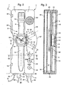
- la figure 1 est une vue générale en perspective d'une boíte de commande selon l'invention,
- la figure 2 est une vue de dessus d'un banc de chronométrage électrique selon l'invention, comportant au moins une boíte de commande telle que représentée à la figure 1, dans laquelle est placé un chronographe-bracelet de type courant à deux poussoirs,
- la figure 3 est une vue simplifiée en coupe longitudinale du banc de chronométrage de la figure 2,
- la figure 4 est une vue d'une extrémité de la boíte de commande, suivant la flèche IV de la figure 2,
- la figure 5 est une vue en coupe transversale suivant la ligne V-V de la figure 2, à une échelle agrandie, et
- la figure 6 est une vue en coupe transversale suivant la ligne VI-VI de la figure 2, à une échelle agrandie.
- FIG. 1 is a general perspective view of a control box according to the invention,
- FIG. 2 is a top view of an electric timing bench according to the invention, comprising at least one control box as shown in FIG. 1, in which is placed a current type wrist chronograph with two pushers,
- FIG. 3 is a simplified view in longitudinal section of the timing bench of FIG. 2,
- FIG. 4 is a view of one end of the control box, along arrow IV of FIG. 2,
- FIG. 5 is a cross-sectional view along the line VV of FIG. 2, on an enlarged scale, and
- Figure 6 is a cross-sectional view along line VI-VI of Figure 2, on an enlarged scale.
En référence aux figures 1 à 6, la boíte de commande 1 est destinée à
contenir et à actionner un chronographe-bracelet 2 d'un type courant, comportant une
boíte de montre 3 et un bracelet souple à deux brins 4 et 5. Le chronographe 2 est de
préférence à quartz; il comporte des organes d'affichage 6 qui sont analogiques dans
le cas présent, une couronne de mise à l'heure 7 et deux poussoirs 8 et 9 pour le
chronométrage. De manière classique, une première pression sur le poussoir 8 met
en marche le chronométrage (fonction START), une pression ultérieure sur le
poussoir 8 arrête le chronométrage (fonction STOP), une première pression sur le
poussoir 9 quand le chronométrage est en marche arrête les organes d'affichage pour
permettre la lecture d'un temps
intermédiaire (fonction LAP), une pression ultérieure sur
le poussoir 9 produit un rattrapage de l'affichage pour
continuer à indiquer le temps chronométré, et une pression
sur le poussoir 9 après arrêt du chronométrage remet à
zéro les compteurs et les organes d'affichage
correspondants du chronographe. Le cas échéant, le
chronographe 2 peut encore comporter un ou plusieurs
autres poussoirs pour commander des fonctions spéciales,
de manière connue.Referring to Figures 1 to 6, the
La boíte de commande 1 comporte un corps 11 en
matière synthétique moulée présentant, dans sa face
supérieure, un logement 12 agencé pour recevoir le
chronographe 2. Le logement 12 comprend une partie
élargie 13, dans laquelle la boíte 3 du chronographe 2 est
calée latéralement au moyen d'un coussinet 14, et deux
parties plus étroites 15 et 16 dans lesquelles se logent
les brins 4 et 5 du bracelet. Le logement 12 est fermé sur
le dessus par un couvercle 17 articulé par des charnières
18 sur le corps 11 de la boíte 1, ce couvercle laissant
voir au moins les organes d'affichage 6 du chronographe 2.
Dans le cas présent, le couvercle 17 est fait d'une
matière synthétique transparente et il présente, au-dessus
des organes d'affichage 6, une partie en forme de loupe 19
facilitant la lecture des temps affichés. Le couvercle 17
protège le chronographe 2 et le maintient dans son
logement 12 aussi bien pendant l'utilisation du banc de
chronométrage que pour le conditionnement, le stockage, la
vente et le transport de l'ensemble.The
D'autre part, le corps 11 de la boíte 1 définit une
cavité 21 destinée à contenir des composants électriques.
Cette cavité est obturée par un fond amovible 22 fixé par
des vis à des piliers 23 qui supportent aussi un circuit
imprimé 24 dans la cavité 21.On the other hand, the
Comme on le voit dans la figure 2, la boíte de
commande 1 présente une face latérale 26 dont la partie
centrale 27 est convexe, tandis que sa face latérale
opposée 28 a une partie centrale concave 29 de forme
complémentaire à la partie convexe 27. Ceci permet de
juxtaposer plusieurs boítes de commande 1 identiques,
comme on l'a indiqué par une seconde boíte de commande 1'
dans la figure 2, afin de constituer un banc de
chronométrage multiple contenant plusieurs chronographes 2
qui peuvent fonctionner indépendamment ou en combinaison,
comme on le décrira plus loin. Les boítes de commande 1 et
1' peuvent comporter des moyens d'attache tels que des
bandes auto-agrippantes, permettant de les fixer les unes
aux autres.As seen in Figure 2, the box of
Comme on le voit particulièrement dans les figures 2
et 4, une face d'extrémité 30 de la boíte de commande 1
est équipée de cinq raccords d'entrée ou sortie, en
l'occurrence cinq prises électriques 31 à 35 qui sont
raccordées au circuit imprimé 24. La prise 31 est une
entrée d'alimentation, destinée à recevoir un connecteur
bipolaire 36 d'un câble d'alimentation basse tension 37.
Les deux prises 34 et 35 sont des entrées destinées à
recevoir, par des câbles 38 et 39 équipés de connecteurs
40 et 41, des signaux électriques d'entrée provenant de
deux cellules de chronométrage distinctes, par exemple une
cellule de départ raccordée à la prise 34 et une cellule
intermédiaire ou d'arrivée, raccordée à la prise 35. Les
deux prises 32 et 33 sont destinées à recevoir chacune un
connecteur multipolaire 42, par exemple à quatre pôles,
d'un câble 43 reliant en cascade la boíte de commande 1 à
une autre boíte identique 1' pour lui transmettre les
signaux d'entrée reçus sur les prises 34 et 35. Les
chronographes respectifs des boítes ainsi couplées
pourront fonctionner en combinaison, par exemple en
utilisant les mêmes signaux de différentes manières.As seen particularly in Figures 2
and 4, an
La cavité 21 contient en outre deux électro-aimants
51 et 52 agissant dans la direction de leurs axes
longitudinaux respectifs 53 et 54 pour presser les
poussoirs 8 et 9 du chronographe 2. Comme on le voit dans
la figure 5, la tige axiale mobile 55 de chaque électroaimant
est munie d'un capuchon protecteur 56 capable de
s'appuyer contre le poussoir sans le détériorer. Les deux
électro-aimants sont fixés par des vis 57 à une plaque de
support 58 montée dans la cavité 21. Leur alimentation est
commandée par des éléments du circuit imprimé 24 en
fonction des signaux d'entrée reçus par l'une des prises
32 à 35 et en fonction d'un mode de fonctionnement
sélectionné du banc de chronométrage.The
La face supérieure de la boite de commande 1 présente
en outre, à côté du couvercle 17, un générateur acoustique
60, un bouton sélecteur de temps d'affichage 61, un bouton
sélecteur de mode 62 et un bouton-poussoir de remise à
zéro 63.The upper face of the
Le générateur acoustique 60, par exemple du type
piézo-électrique, émet des signaux sonores donnant
quittance de l'actionnement mannuel des boutons 61 à 63.The
Le sélecteur de mode 62 a trois positions correspondant aux modes suivants :
- Dans le mode OFF, les signaux d'entrée sont
verrouillés. Cependant ils peuvent être transmis entre les
prises 32 à 35 pour passer d'une boíte de commande à une autre. - Dans le mode normal NORM, un signal d'entrée sur
la
prise 34 produit la fonction START, par action de l'électro-aimant 51 sur lepoussoir 8, et un signal d'entrée sur laprise 35 produit la fonction STOP, par action sur le même poussoir. - Le mode LAP sert à mesurer et afficher des temps
intermédiaires lorsque le chronographe est en marche. Un
premier signal d'entrée sur la
prise 34 produit la fonction START en pressant sur lepoussoir 8, puis un deuxième signal d'entrée sur laprise 35 produit l'affichage d'un temps intermédiaire par pression sur l'autrepoussoir 9 par l'électo-aimant 52. Ce temps reste affiché pendant une durée définie par l'utilisateur au moyen du sélecteur 61 (4 s, 8 s ou 16 s dans l'exemple représenté), puis l'appareil effectue automatiquement une deuxième pression sur le poussoir 9 pour continuer l'affichage du temps chronométré. Dans ce mode, la fonction STOP ne peut pas être effectuée; l'utilisateur doit d'abord sélectionner le mode normal.
- In OFF mode, the input signals are locked. However they can be transmitted between
sockets 32 to 35 to go from one control box to another. - In the normal NORM mode, an input signal on the
socket 34 produces the START function, by action of theelectromagnet 51 on thepusher 8, and an input signal on thesocket 35 produces the STOP function, by action on the same button. - LAP mode is used to measure and display split times when the chronograph is running. A first input signal on
socket 34 produces the START function by pressing push-button 8, then a second input signal onsocket 35 produces the display of an intermediate time by pressing on the other push-button 9 by theelectromagnet 52. This time remains displayed for a duration defined by the user by means of the selector 61 (4 s, 8 s or 16 s in the example shown), then the device automatically performs a second press on push-button 9 to continue displaying the timed time. In this mode, the STOP function cannot be performed; the user must first select the normal mode.
La remise à zéro du chronographe (RESET) est
verrouillée dans les modes NORM et LAP. Elle s'effectue
manuellement par pression sur le bouton 63 quand
l'appareil est en mode OFF. L'électro-aimant 52 presse
alors le poussoir 9.Resetting the chronograph (RESET) is
locked in NORM and LAP modes. It takes place
manually by pressing
On comprend ainsi que le banc de chronométrage selon
l'invention peut comprendre une seule boíte de commande 1
contenant un chronographe 2, ou plusieurs de ces boites de
commande, contenant un nombre quelconque de chronographes,
et que ces chronographes peuvent fonctionner simultanément
dans des modes différents et en fonction de signaux
d'entrée provenant de différentes cellules de
chronométrage. Par exemple, une première boíte de commande
1 peut être couplée à une cellule de départ et à une
cellule d'arrivée et fonctionner en mode normal. Une
deuxième boíte de commande 1' peut être couplée à la
première et fonctionner soit en mode normal, à titre de
sécurité, soit en mode LAP pour afficher des temps
intermédiaires à chaque passage devant la cellule
d'arrivée. Une troisième boíte de commande peut être
reliée à la deuxième, pour recevoir le signal de départ,
et à une troisième cellule pour mesurer soit un autre
temps intermédiaire (en mode LAP), soit un autre temps
final.It is thus understood that the timing bench according to
the invention can comprise a
Dans n'importe quelle configuration du banc de chronométrage, comportant un ou plusieurs chronographes, le banc fonctionne de manière automatique dès qu'on a sélectionné le ou les modes de fonctionnement. Il est donc utilisable d'une manière fiable et précise par n'importe quelle personne, même si l'utilisateur est seul et chronomètre ses propres performances.In any configuration of the bench timing, comprising one or more chronographs, the bench works automatically as soon as we have selected the operating mode (s). It is therefore can be used reliably and precisely by anyone which person, even if the user is alone and times his own performances.
D'autre part, la boíte de commande 1 est un objet de
petites dimensions, déterminées avant tout par celles du
chronographe 2. Elle est donc légère, peu encombrante et
peut être transportée dans une poche de vêtement. Cette
boíte constitue un excellent emballage protecteur pour le
chronographe et peut servir avantageusement pour le
conditionnement et la vente de celui-ci. La description
qui précède montre également que cette boíte de commande,
composée d'éléments simples et peu coûteux, peut être
produite à bas prix et acquise par n'importe quel amateur.
Celui-ci peut l'utiliser avec un chronographe bracelet
qu'il possède déjà et qu'il porte au poignet dans la vie
courante.On the other hand, the
Bien que l'exemple décrit ci-dessus utilise un chronographe bracelet ordinaire, actionné par pression sur ses poussoirs, la présente invention peut s'étendre à d'autres modes d'actionnement du chronographe par la boíte de commande, si ces deux éléments sont construits de manière appropriée. Par exemple, les poussoirs pourraient constituer des contacts électriques coopérant avec des contacts de la boíte de commande pour recevoir des impulsions d'actionnement. Dans d'autres variantes, la transmission de telles impulsions entre la boíte de commande et le chronographe pourrait se faire par rayonnement infrarouge, par ondes hertziennes ou par un système électromagnétique. Des modes de transmission similaires sont utilisables entre les cellules de chronométrage et la ou les boítes de commande.Although the example described above uses a ordinary bracelet chronograph, actuated by pressing its pushers, the present invention may extend to other modes of chronograph activation by the box command, if these two elements are constructed of appropriately. For example, the pushers could constitute electrical contacts cooperating with control box contacts for receiving actuation pulses. In other variants, the transmission of such pulses between the order and the chronograph could be done by infrared radiation, radio waves or a electromagnetic system. Modes of transmission similar are usable between the cells of timing and the control unit (s).
Claims (10)
- Automatic electric timing bench including at least one chronograph (2) provided with at least two control elements (8, 9), and at least one control box (1) provided with a housing (12) in which the chronograph is removably placed, the control box including input ports (34, 35), for receiving electric input signals originating from cells for detecting the events to be timed, and actuating means (51, 52) acting on the chronograph control elements as a function of said input signals,
characterized in that the control box (1) includes a manual mode selector (62), allowing at least two different modes for actuating the chronograph control elements to be selected, and further includes auxiliary input and output electric ports (32, 33) arranged for connecting it to at least one other identical control box (1'), for transmitting said input signals between said control boxes. - Timing bench according to claim 1, characterized in that the chronograph is a chronograph wristwatch whose said control elements are lateral push buttons (8, 9) and in that said actuating means include electromagnets (51, 52) acting on said push buttons.
- Timing bench according to claim 1 or 2, characterized in that the control box (1) includes a manual reset control element (063), arranged for generating resetting of the chronograph by said actuating means.
- Timing bench according to claim 1, characterized in that the control box (1) includes, on two opposite lateral faces, mutually complementary shapes (27, 29) allowing it to be joined to other identical control boxes, to form a timing bench containing several chronographs.
- Timing bench according to any of the preceding claims, characterized in that said housing (12) of the control box is closed by a cover (17) having at least one transparent portion facing display elements (6) of the chronograph.
- Timing bench according to claim 5, characterized in that the cover (17) includes a magnifying glass (19) facing said display elements.
- Timing bench according to claim 2, characterized in that said housing (12) includes an enlarged portion (13), formed for accommodating the chronograph case (3) and positioning the latter with respect to the actuating elements (51, 52), and at least one narrower portion (15, 16) formed for accommodating the wristlet.
- Control box (1) for an electric timing bench, said box including an upper face provided with a housing (12) arranged for removably accommodating a chronograph wristwatch (2) having push button controls (8, 9), said control box including input ports (34, 35), for receiving electric input signals originating from cells for detecting the events to be timed, and electromagnets (51, 52) acting on the chronograph push buttons as a function of said input signals,
characterized in that the control box (1) includes a manual mode selector (62), allowing at least two different modes for actuating the chronograph control elements to be selected, and further includes auxiliary input and output electric ports (32, 33) arranged for connecting it to at least one other identical control box (1'), for transmitting said input signals between said control boxes. - Control box according to claim 8, characterized in that said housing (12) is closed by a cover (17) having at least one transparent portion (19) facing display elements (6) of the chronograph.
- Control box according to claim 8 or 9, characterized in that it constitutes a packaging for the chronograph.
Priority Applications (5)
| Application Number | Priority Date | Filing Date | Title |
|---|---|---|---|
| DE69727564T DE69727564D1 (en) | 1997-09-05 | 1997-09-05 | Bench for electric chronometer and control box for it |
| EP97202727A EP0901052B1 (en) | 1997-09-05 | 1997-09-05 | Electrical chronometer bench and controlbox for such bench |
| US09/140,402 US6067276A (en) | 1997-09-05 | 1998-08-26 | Electric timing bench and control box for the same |
| CNB981203000A CN1137416C (en) | 1997-09-05 | 1998-09-04 | Electric timing bench and control box for same |
| JP10252302A JPH11142552A (en) | 1997-09-05 | 1998-09-07 | Electric timing-bench and its control box |
Applications Claiming Priority (1)
| Application Number | Priority Date | Filing Date | Title |
|---|---|---|---|
| EP97202727A EP0901052B1 (en) | 1997-09-05 | 1997-09-05 | Electrical chronometer bench and controlbox for such bench |
Publications (2)
| Publication Number | Publication Date |
|---|---|
| EP0901052A1 EP0901052A1 (en) | 1999-03-10 |
| EP0901052B1 true EP0901052B1 (en) | 2004-02-11 |
Family
ID=8228705
Family Applications (1)
| Application Number | Title | Priority Date | Filing Date |
|---|---|---|---|
| EP97202727A Expired - Lifetime EP0901052B1 (en) | 1997-09-05 | 1997-09-05 | Electrical chronometer bench and controlbox for such bench |
Country Status (5)
| Country | Link |
|---|---|
| US (1) | US6067276A (en) |
| EP (1) | EP0901052B1 (en) |
| JP (1) | JPH11142552A (en) |
| CN (1) | CN1137416C (en) |
| DE (1) | DE69727564D1 (en) |
Families Citing this family (2)
| Publication number | Priority date | Publication date | Assignee | Title |
|---|---|---|---|---|
| DE102004001196B4 (en) * | 2004-01-07 | 2011-04-28 | Brömme, Jürgen | Watches servants |
| CN112613351A (en) * | 2020-12-03 | 2021-04-06 | 江阴众和电力仪表有限公司 | Intelligent distribution box and operation method thereof |
Family Cites Families (5)
| Publication number | Priority date | Publication date | Assignee | Title |
|---|---|---|---|---|
| DE317995C (en) * | ||||
| US450966A (en) * | 1891-04-21 | Island | ||
| CH49005A (en) * | 1910-02-11 | 1911-01-02 | Longines Francillon & Co Fab D | Electrical control device of a pocket chronograph |
| US1146320A (en) * | 1914-03-18 | 1915-07-13 | Alanson L Fish | Automatic timing device. |
| US3596103A (en) * | 1968-11-18 | 1971-07-27 | Klon E Matthews | Multiple timing apparatus for track events and the like |
-
1997
- 1997-09-05 EP EP97202727A patent/EP0901052B1/en not_active Expired - Lifetime
- 1997-09-05 DE DE69727564T patent/DE69727564D1/en not_active Expired - Lifetime
-
1998
- 1998-08-26 US US09/140,402 patent/US6067276A/en not_active Expired - Fee Related
- 1998-09-04 CN CNB981203000A patent/CN1137416C/en not_active Expired - Fee Related
- 1998-09-07 JP JP10252302A patent/JPH11142552A/en active Pending
Also Published As
| Publication number | Publication date |
|---|---|
| US6067276A (en) | 2000-05-23 |
| CN1213790A (en) | 1999-04-14 |
| EP0901052A1 (en) | 1999-03-10 |
| JPH11142552A (en) | 1999-05-28 |
| DE69727564D1 (en) | 2004-03-18 |
| CN1137416C (en) | 2004-02-04 |
Similar Documents
| Publication | Publication Date | Title |
|---|---|---|
| CH694231A5 (en) | Electronic device, in particular electronic timepiece part, multi-mode. | |
| EP1701229B1 (en) | Electronic watch with compass function | |
| CH615582A5 (en) | Cardiac monitoring device | |
| EP1070997A1 (en) | Reversible wrist-watch | |
| FR2628856A1 (en) | BRACELET WATCH AND COMPUTER SET FOR THE PRACTICE OF CYCLING | |
| CH684618B5 (en) | Timepiece for simultaneous display of the time for at least two time zones. | |
| EP0360140B1 (en) | Skeleton watch showing the whole mechanism or a part of the same | |
| WO1997016993A1 (en) | Modular jewellery item, particularly a ring, earring, pendant or timepiece such as a watch | |
| WO2014083001A2 (en) | Touch-sensitive portable electronic object | |
| WO1998032057A1 (en) | Wristband with modular structure | |
| EP0901052B1 (en) | Electrical chronometer bench and controlbox for such bench | |
| FR2501389A1 (en) | MODE SWITCHING DEVICE FOR AN ELECTRONIC WATCH | |
| WO2017006162A2 (en) | Reversible hybrid watch | |
| EP1519457B1 (en) | Adaptor for a portable electronic device and transmission system between these elements | |
| FR2626685A1 (en) | WATCH COMPRISING AN ELECTRIC BRAKE CONTACT | |
| EP3571552B1 (en) | Modular watch piece with means of communication with a third-part electronic device | |
| CH694176A5 (en) | Electric chronometry bench with its control box comprises classic bracelet chronograph and control box provided with location of chronograph and transparent cover | |
| EP1134630B1 (en) | Means for exchanging information with a portable object, in particular a time-piece | |
| CH711300A1 (en) | Hybrid reversible watch. | |
| EP0759584A1 (en) | Synchronisation means with time zone detector | |
| CH714294B1 (en) | Wristwatch comprising a mechanical watch movement and an electronic module. | |
| EP0027250A1 (en) | Clockwork with display of seconds on demand | |
| EP0683441A1 (en) | Electronic watch with minute repetition function | |
| FR2823346A1 (en) | PENDULUM FOR CHESS GAME | |
| FR2523836A3 (en) | APPARATUS FOR MEASURING THE REACTION SPEED OF A HUMAN BEING |
Legal Events
| Date | Code | Title | Description |
|---|---|---|---|
| PUAI | Public reference made under article 153(3) epc to a published international application that has entered the european phase |
Free format text: ORIGINAL CODE: 0009012 |
|
| AK | Designated contracting states |
Kind code of ref document: A1 Designated state(s): DE DK ES FR GB IT |
|
| 17P | Request for examination filed |
Effective date: 19990910 |
|
| AKX | Designation fees paid |
Free format text: DE DK ES FR GB IT |
|
| 17Q | First examination report despatched |
Effective date: 20020925 |
|
| GRAP | Despatch of communication of intention to grant a patent |
Free format text: ORIGINAL CODE: EPIDOSNIGR1 |
|
| GRAP | Despatch of communication of intention to grant a patent |
Free format text: ORIGINAL CODE: EPIDOSNIGR1 |
|
| GRAS | Grant fee paid |
Free format text: ORIGINAL CODE: EPIDOSNIGR3 |
|
| GRAA | (expected) grant |
Free format text: ORIGINAL CODE: 0009210 |
|
| RBV | Designated contracting states (corrected) |
Designated state(s): DE ES FR GB IT |
|
| AK | Designated contracting states |
Kind code of ref document: B1 Designated state(s): DE ES FR GB IT |
|
| PG25 | Lapsed in a contracting state [announced via postgrant information from national office to epo] |
Ref country code: IT Free format text: LAPSE BECAUSE OF FAILURE TO SUBMIT A TRANSLATION OF THE DESCRIPTION OR TO PAY THE FEE WITHIN THE PRESCRIBED TIME-LIMIT;WARNING: LAPSES OF ITALIAN PATENTS WITH EFFECTIVE DATE BEFORE 2007 MAY HAVE OCCURRED AT ANY TIME BEFORE 2007. THE CORRECT EFFECTIVE DATE MAY BE DIFFERENT FROM THE ONE RECORDED. Effective date: 20040211 Ref country code: GB Free format text: LAPSE BECAUSE OF FAILURE TO SUBMIT A TRANSLATION OF THE DESCRIPTION OR TO PAY THE FEE WITHIN THE PRESCRIBED TIME-LIMIT Effective date: 20040211 Ref country code: ES Free format text: LAPSE BECAUSE OF FAILURE TO SUBMIT A TRANSLATION OF THE DESCRIPTION OR TO PAY THE FEE WITHIN THE PRESCRIBED TIME-LIMIT Effective date: 20040211 |
|
| REG | Reference to a national code |
Ref country code: GB Ref legal event code: FG4D Free format text: NOT ENGLISH |
|
| REF | Corresponds to: |
Ref document number: 69727564 Country of ref document: DE Date of ref document: 20040318 Kind code of ref document: P |
|
| PG25 | Lapsed in a contracting state [announced via postgrant information from national office to epo] |
Ref country code: DE Free format text: LAPSE BECAUSE OF FAILURE TO SUBMIT A TRANSLATION OF THE DESCRIPTION OR TO PAY THE FEE WITHIN THE PRESCRIBED TIME-LIMIT Effective date: 20040512 |
|
| GBV | Gb: ep patent (uk) treated as always having been void in accordance with gb section 77(7)/1977 [no translation filed] |
Effective date: 20040211 |
|
| PLBE | No opposition filed within time limit |
Free format text: ORIGINAL CODE: 0009261 |
|
| STAA | Information on the status of an ep patent application or granted ep patent |
Free format text: STATUS: NO OPPOSITION FILED WITHIN TIME LIMIT |
|
| 26N | No opposition filed |
Effective date: 20041112 |
|
| PG25 | Lapsed in a contracting state [announced via postgrant information from national office to epo] |
Ref country code: FR Free format text: LAPSE BECAUSE OF NON-PAYMENT OF DUE FEES Effective date: 20050531 |
|
| REG | Reference to a national code |
Ref country code: FR Ref legal event code: ST |