EP0900908A2 - Lockable device for the stocking of appliances - Google Patents
Lockable device for the stocking of appliances Download PDFInfo
- Publication number
- EP0900908A2 EP0900908A2 EP98113427A EP98113427A EP0900908A2 EP 0900908 A2 EP0900908 A2 EP 0900908A2 EP 98113427 A EP98113427 A EP 98113427A EP 98113427 A EP98113427 A EP 98113427A EP 0900908 A2 EP0900908 A2 EP 0900908A2
- Authority
- EP
- European Patent Office
- Prior art keywords
- closure element
- plate
- guide elements
- closure
- groove
- Prior art date
- Legal status (The legal status is an assumption and is not a legal conclusion. Google has not performed a legal analysis and makes no representation as to the accuracy of the status listed.)
- Granted
Links
- 241000446313 Lamella Species 0.000 claims description 2
- 238000006073 displacement reaction Methods 0.000 description 4
- 238000004804 winding Methods 0.000 description 2
- 208000036829 Device dislocation Diseases 0.000 description 1
- 241000237858 Gastropoda Species 0.000 description 1
- 238000005299 abrasion Methods 0.000 description 1
- XAGFODPZIPBFFR-UHFFFAOYSA-N aluminium Chemical compound [Al] XAGFODPZIPBFFR-UHFFFAOYSA-N 0.000 description 1
- 229910052782 aluminium Inorganic materials 0.000 description 1
- 230000003247 decreasing effect Effects 0.000 description 1
- 238000004519 manufacturing process Methods 0.000 description 1
Images

Classifications
-
- E—FIXED CONSTRUCTIONS
- E06—DOORS, WINDOWS, SHUTTERS, OR ROLLER BLINDS IN GENERAL; LADDERS
- E06B—FIXED OR MOVABLE CLOSURES FOR OPENINGS IN BUILDINGS, VEHICLES, FENCES OR LIKE ENCLOSURES IN GENERAL, e.g. DOORS, WINDOWS, BLINDS, GATES
- E06B9/00—Screening or protective devices for wall or similar openings, with or without operating or securing mechanisms; Closures of similar construction
- E06B9/02—Shutters, movable grilles, or other safety closing devices, e.g. against burglary
- E06B9/08—Roll-type closures
- E06B9/11—Roller shutters
- E06B9/115—Roller shutters specially adapted for furniture
-
- A—HUMAN NECESSITIES
- A47—FURNITURE; DOMESTIC ARTICLES OR APPLIANCES; COFFEE MILLS; SPICE MILLS; SUCTION CLEANERS IN GENERAL
- A47B—TABLES; DESKS; OFFICE FURNITURE; CABINETS; DRAWERS; GENERAL DETAILS OF FURNITURE
- A47B96/00—Details of cabinets, racks or shelf units not covered by a single one of groups A47B43/00 - A47B95/00; General details of furniture
-
- E—FIXED CONSTRUCTIONS
- E06—DOORS, WINDOWS, SHUTTERS, OR ROLLER BLINDS IN GENERAL; LADDERS
- E06B—FIXED OR MOVABLE CLOSURES FOR OPENINGS IN BUILDINGS, VEHICLES, FENCES OR LIKE ENCLOSURES IN GENERAL, e.g. DOORS, WINDOWS, BLINDS, GATES
- E06B9/00—Screening or protective devices for wall or similar openings, with or without operating or securing mechanisms; Closures of similar construction
- E06B9/56—Operating, guiding or securing devices or arrangements for roll-type closures; Spring drums; Tape drums; Counterweighting arrangements therefor
- E06B9/58—Guiding devices
Definitions
- the invention relates to a device for receiving devices and objects with a sliding closure element, through which one for receiving the Devices and objects serving space can be limited, as well as with guide elements, in which the closure element is slidably received.
- Such devices are known in the field of living room and kitchen furniture, roller or sectional door armor are often used as the closure element.
- the closure element is usually in its edge areas in parallel to each other arranged guide rails added that a shift allows the closure element in different positions, whereby corresponding areas of the device for removing or setting Be made accessible to devices or objects.
- Generic devices are carried out, for example, in such a way that a base plate and two side parts arranged vertically and in parallel thereon are provided, and the closure element is guided between the side parts.
- the state of the device is the closure-side end region of the closure element on a corresponding surface serving as a stop, for example Is part of the base plate.
- the closure element is displaced on the corresponding side of the device in such a way that between the closure-side end region of the closure device and an opening is created for the surface serving as a stop, the size of which depends on the position of the closure device.
- the locking device on the side surface adjacent to the front or also on an opposite back of the device moved and here accordingly added. Because in this case a maximum displacement by the Dimension of the corresponding walls is limited, the closure element often wound on an axis or in the form of a snail. In both cases, a corresponding space is required, at least that The space requirement of the wound roller or sectional door corresponds to that for Inclusion of equipment or objects available space accordingly decreased.
- this object is thereby achieved solved that the guide elements in the direction of movement of the closure element are arranged such that the closure element at least partially on the Side of the device is receivable, which extends into an area which in Locked position of the device the closure-side end region of the closure element is adjacent.
- This ensures that the area for Inclusion of the closure element at least partially around the side of the device is extendable, which extends into an area which is in the closed position the device the closure-side end region of the closure element is adjacent or directly or indirectly adjacent to this.
- the page the device which extends into an area which is in the closed position of the Device adjacent to the end portion of the closure element on the closure side is formed by a plate serving as a working and storage surface.
- the plate has a space for receiving the closure element is particularly advantageous which extends below the surface of the plate and are arranged in the guide elements.
- the present invention resides in the fact that it is usually present anyway serving as a working and storage surface plate for receiving the closure element serves and thus the total available length for Inclusion of the closure element around the length of the plate in the direction of movement of the closure element is enlarged. Because the space is below the surface The surface of the plate can still be used as a work surface and storage area be used, at the same time the correspondingly recorded in this room Part of the closure element is not visible from the outside. The creation of Axes or equivalent devices for receiving the wound closure element is therefore superfluous.
- the invention Device on two side parts, which comprise guide elements and between which the closure element is slidably disposed.
- the side parts correspond approximately in their spacing to the width of the closure element, the guide elements, which are arranged in the side parts, the closure element in the deviating from the direction of movement of the closure element Takes directions positively.
- the guide elements the side parts and the guide elements of the plate releasably connectable to each other are. So it is possible to first side panels with appropriate guide elements to accommodate the areas of the closure element to manufacture and independent of which the plate serving as work and storage surface with guide elements to be provided, the end regions of the guide elements of the side parts and the plate are releasably connectable. To move it smoothly to ensure the closure element, the guide elements of Side parts and the plate provided with the same profile and designed in such a way that a precisely fitting connection of the end regions of the guide elements is possible is. For this purpose, an end area can be provided with appropriate extension pieces, which can be positively received in the end region that can be connected to it.
- the guide elements of the plate through a provided in the surface of the plate Opening.
- the guide element provided in the plate can have a straight and a curved section, the straight section is received in the plate and the curved section accordingly protrudes from the opening provided in the surface of the plate.
- the in the Surface of the plate provided opening can be from both the inside of the Device as well as from the outside, for example, through a housing cover be covered so that it is not visible from the outside.
- the through region of the guide element which extends the opening of the surface of the plate is correspondingly above the plate with the guide elements of the side parts connected.
- the side parts arranged vertically on the plate serving as a work and storage surface are.
- the device according to the invention essentially has one flat plate and two side parts arranged vertically on it, the through the opposite guide elements of the side parts as well the sliding surface defined by the plate represents the area in which the closure element can be moved.
- the side parts are essentially one have a rectangular shape. It can be in the closed state of the device on the front of the side parts of the closure-side end area of the Closure element and for example on the opposite back of the Device of the second end region of the closure element can be provided.
- the closure device moves out of this position, there is first a vertical upward movement of the closure-side end region of the closure element until the upper edge of the side part is reached.
- the second end region of the closure element moves in accordance with the arrangement of the guide elements on the side, which is in the closed position of the device extends into a region which is the closure-side end region of the closure element is adjacent.
- the invention of this page is by serving as a work and storage area Plate formed. It is possible to move the closure element until the the second end region of the closure element opposite the end region on the closure side touches the corresponding limit of the plate.
- By a appropriate dimensioning of the plate is therefore a maximum adjustability of the closure element can be specified.
- the closure element such as the front, the top and the back the side parts is moved so that the limitable by the closure element Space is largely open.
- the guide elements are designed as rails is particularly advantageous are a first groove for receiving the edge regions of the closure element, which are in the direction perpendicular to the direction of movement of the closure element extend, have.
- the closure element is thus advantageous in both Edge areas through the two opposite with grooves Rails added, which means only one direction in the direction of movement of the closure element is possible and the closure element in it deviating directions is positively received.
- the rails can for example, be integrated into the side parts of the device according to the invention or can also be releasably or non-releasably connected to it.
- the Guide elements of the plate can be designed as rails which have a first groove Have recording of the edge areas of the closure element and in the Plate are releasably receivable. It is conceivable that the provided in the plate Space for receiving the closure element on the underside freely accessible is, so that an exact assembly and also an exchange of the in the plate recorded rail is easily possible.
- a second groove which has a tension element with a first extension piece, wherein in a region of the closure element, a second extension piece is provided that is connectable to the first extension.
- a force when moving the closure element on this is exercisable, which causes a by the tension element when opening the device cushioned stop is reached in an end position in the open position.
- the closure element is closed by the tension element according to the invention relieved, since the tension element in the open state of the device is excited and thus a force acting in the direction of closure on the Closing element exercises.
- the first and the second extension piece are arranged in such a way that this is advantageous only from a certain position of the Closure element are in contact with each other.
- the tension element designed as a spiral spring and by means of a foreseeable in the second groove Bolt or a screw fixable.
- the tension element or the tongue in the second groove is stretched in that, for example, in the first groove the first attachment is taken up by the second attachment piece. From that through a bolt or a screw fixable starting point of the spring in the second groove or the spring length, it depends on the position from which the closure element by means of the second extension with the spring through the first Attachment is connectable, making this a corresponding in the closed position oriented force is exercisable.
- closure element has a lamella Rolltor- or sectional door armor is formed.
- this tank will be made of aluminum, with the in the guide elements recordable end regions of the slats advantageously have abrasion-resistant plastic.
- sockets are arranged in the space limited by the closure element.
- Such an arrangement of sockets has the advantage that the devices set in the device via short cable routes to a power supply are connectable and also in the closed state of the device can stay connected.
- the sockets are advantageous due to a manifold connected to a stationary power supply.
- a substantially vertical arranged wall can be provided. The excess can be behind this wall Cable remnants of the electrical devices are inserted, which causes the Can not hinder the user's gripping and working area.
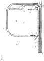
- FIG. 1 shows in cross section the device 10 according to the invention with the plate 50 serving as a working and storage surface and one of the plates arranged thereon Side parts 60.
- the side part 60 has a guide element 40 which adjoins three Sides of the side part 60 extends.
- the plate 50 has a space 502 in which a guide element 52 is arranged, which is a straight and a curved Section.
- the curved section of the guide element 52 projects through an opening 504 of the plate 50 out of this and is advantageously detachable with the Guide element 40 of the side part 60 can be connected.
- the closure-side end region 24 of the closure element 20 is closed Condition of the device 10 on the plate 50. It is also possible that the plate 50 and the closure-side end region 24 are not immediate, but communicate with each other by means of a strip or cover. Will that Closure element 20 moved from the position shown in Fig. 1 is carried out first a vertical displacement of the end portion 24 of the closure element 20 to the curved and then the horizontal area of the guide element 40 of the side part 60 is reached. During the displacement of the closure element 20 is the one not shown in FIG. 1 from the closure side End region 24 spaced second end region of the closure element accordingly on the back of the side part 60 or already included in the plate 50.
- the guide elements 40, 52 are such in Direction of movement of the closure element arranged that the closure element 20 at least partially on the side of the device formed by the plate 50 10 is receivable, the in the closed position shown in Fig. 1 Device 10 to the end portion 24 of the closure element on the closure side 20 adjacent.
- the closure element 20 is largely displaced in the guide elements 40 and 52 possible without winding up an axis is necessary.
- the space 30, which in the closed state the device 10 through the side parts 60 and through the closure element 20th and the plate 50 is limited, easily accessible.
- sockets 140 which are preferably with a line with each other and with a power supply device are connectable. There is a room just below socket 140 which can be delimited by the wall 150 and which is used to hold the cables Serves electrical appliances.
- a first extension 110 is located in the guide element 52 of the plate 50, the corresponding movement of the closure element of this or of a second extension piece arranged thereon is movable.
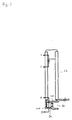
- Fig. 2 shows in longitudinal section the guide element 52, which in the plate or in the Cavity of the plate is mountable.
- the guide element 52 has a straight one and a curved section. It is designed as a rail in which the as Spring designed tension element 100 is receivable.
- the bolt 130 In one end of the spring there is the bolt 130, which in corresponding walls of the guide element 52 is arranged.
- the bolt 130 represents an end point of the tension element 100, while at the other end region the first extension piece 110 is arranged.
- the extension piece 110 is in a second groove 90, which with the first groove 80 into which the edge regions of the closure element can be received are connected.
- the edge area of the closure element accommodated in the groove 80 comes with a corresponding displacement of the closure element from a predeterminable position with that arranged on the extension piece 110 Projection 120 in contact and stretches the tension element from this position 100.
- it ensures that a closing of the closure element is facilitated in that the tension element in the corresponding tensioned state on the closure element one in the direction of movement exerts effective force.
- Those indicated in Fig. 3 along lines B-B and C-C Sectional drawings of the extension 110 and the spring end with bolt 130 are enlarged in Fig. 2 at the corresponding locations of the guide element 52 shown.
Abstract
Description
Die Erfindung betrifft eine Vorrichtung Zur Aufnahme von Geräten und Gegenständen mit einem verschiebbaren Verschlußelement, durch das ein zur Aufnahme der Geräte und Gegenstände dienender Raum begrenzbar ist, sowie mit Führungselementen, in denen das Verschlußelement verschiebbar aufnehmbar ist.The invention relates to a device for receiving devices and objects with a sliding closure element, through which one for receiving the Devices and objects serving space can be limited, as well as with guide elements, in which the closure element is slidably received.
Derartige Vorrichtungen sind im Bereich von Wohn- und Küchenmöbeln bekannt, wobei als Verschlußelement häufig Roll- oder Sektionaltorpanzer verwendet werden. Das Verschlußelement wird dabei üblicherweise in seinen Randbereichen in zueinander parallel angeordneten Führungsschienen aufgenommen, die ein Verschieben des Verschlußelementes in unterschiedliche Positionen ermöglicht, wodurch entsprechende Bereiche der Vorrichtung zum Entnehmen oder Einstellen von Geräten oder Gegenständen zugänglich gemacht werden. Gattungsgemäße Vorrichtungen werden beispielsweise derart ausgeführt, daß eine Bodenplatte sowie zwei darauf senkrecht und parallel angeordnete Seitenteile vorgesehen sind, und das Verschlußelement zwischen den Seitenteilen geführt wird. Im geschlossenen Zustand der Vorrichtung liegt der verschlußseitige Endbereich des Verschlußelementes an einer entsprechenden als Anschlag dienenden Fläche an, die beispielsweise Bestandteil der Bodenplatte ist. Soll die Vorrichtung geöffnet werden, wird das Verschlußelement auf der entsprechenden Seite der Vorrichtung derart verschoben, daß zwischen dem verschlußseitigen Endbereich der Verschlußvorrichtung und der als Anschlag dienenden Fläche eine Öffnung entsteht, deren Größe von der Stellung der Verschlußvorrichtung abhängt. Gleichzeitig wird die Verschlußvorrichtung auf die der Vorderseite benachbarte Seitenfläche oder auch auf eine gegenüberliegende Rückseite der Vorrichtung verschoben und hier entsprechend aufgenommen. Da in diesem Fall eine maximale Verschiebbarkeit durch die Dimension der entsprechenden Wandungen beschränkt wird, wird das Verschlußelement häufig auf einer Achse oder in Form einer Schnecke aufgewickelt. In beiden Fällen wird dazu ein entsprechender Raum benötigt, der zumindest dem Platzbedarf des aufgewickelten Roll- oder Sektionaltores entspricht und den zur Aufnahme von Geräten oder Gegenständen zur Verfügung stehenden Raum entsprechend verringert.Such devices are known in the field of living room and kitchen furniture, roller or sectional door armor are often used as the closure element. The closure element is usually in its edge areas in parallel to each other arranged guide rails added that a shift allows the closure element in different positions, whereby corresponding areas of the device for removing or setting Be made accessible to devices or objects. Generic devices are carried out, for example, in such a way that a base plate and two side parts arranged vertically and in parallel thereon are provided, and the closure element is guided between the side parts. In the closed The state of the device is the closure-side end region of the closure element on a corresponding surface serving as a stop, for example Is part of the base plate. If the device is to be opened, the closure element is displaced on the corresponding side of the device in such a way that between the closure-side end region of the closure device and an opening is created for the surface serving as a stop, the size of which depends on the position of the closure device. At the same time the locking device on the side surface adjacent to the front or also on an opposite back of the device moved and here accordingly added. Because in this case a maximum displacement by the Dimension of the corresponding walls is limited, the closure element often wound on an axis or in the form of a snail. In In both cases, a corresponding space is required, at least that The space requirement of the wound roller or sectional door corresponds to that for Inclusion of equipment or objects available space accordingly decreased.
Es ist die Aufgabe der vorliegenden Erfindung, eine gattungsgemäße Vorrichtung dahingehend weiterzubilden, daß der verfügbare Raum der Vorrichtung optimal nutzbar ist.It is the object of the present invention, a generic device to further develop that the available space of the device is optimal is usable.
Diese Aufgabe wird ausgehend von einer gattungsgemäßen Vorrichtung dadurch gelöst, daß die Führungselemente in Bewegungsrichtung des Verschlußelementes derart angeordnet sind, daß das Verschlußelement wenigstens teilweise auf der Seite der Vorrichtung aufnehmbar ist, die sich in einen Bereich erstreckt, der in Verschlußstellung der Vorrichtung dem verschlußseitigen Endbereich des Verschlußelementes benachbart ist. Dadurch wird gewährleistet, daß der Bereich zur Aufnahme des Verschlußelementes wenigstens teilweise um die Seite der Vorrichtung verlängerbar ist, die sich in einen Bereich erstreckt, der in der Verschlußstellung der Vorrichtung dem verschlußseitigen Endbereich des Verschlußelementes benachbart ist bzw. mittelbar oder unmittelbar an diesen angrenzt. Somit wird erreicht, daß eine weitgehende Öffnung des Verschlußelementes und somit eine gute zugänglichkeit des durch das Verschlußelement begrenzbaren Raumes möglich ist, ohne daß dazu das Aufwickeln des Verschlußelementes, beispielsweise auf einer Achse, erforderlich ist. Der durch das Verschlußelement begrenzbare Raum wird somit erfindungsgemäß beim Öffnen der Vorrichtung durch Verschieben des Verschlußelementes erhalten.Starting from a generic device, this object is thereby achieved solved that the guide elements in the direction of movement of the closure element are arranged such that the closure element at least partially on the Side of the device is receivable, which extends into an area which in Locked position of the device the closure-side end region of the closure element is adjacent. This ensures that the area for Inclusion of the closure element at least partially around the side of the device is extendable, which extends into an area which is in the closed position the device the closure-side end region of the closure element is adjacent or directly or indirectly adjacent to this. Thus it is achieved that an extensive opening of the closure element and thus a good one accessibility of the space delimitable by the closure element is possible, without the winding of the closure element, for example on a Axis, is required. The space that can be limited by the closure element becomes thus according to the invention when opening the device by moving the closure element receive.
Gemäß einer bevorzugten Ausgestaltung der vorliegenden Erfindung wird die Seite der Vorrichtung, die sich in einen Bereich erstreckt, der in Verschlußstellung der Vorrichtung dem verschlußseitigen Endbereich des Verschlußelementes benachbart ist, durch eine als Arbeits- und Abstellfläche dienende Platte gebildet.According to a preferred embodiment of the present invention, the page the device, which extends into an area which is in the closed position of the Device adjacent to the end portion of the closure element on the closure side is formed by a plate serving as a working and storage surface.
Besonders vorteilhaft ist es, wenn die Platte einen Raum zur Aufnahme des Verschlußelementes aufweist, der sich unterhalb der Oberfläche der Platte erstreckt und in dem Führungselemente angeordnet sind. Dadurch ist es möglich, daß das Verschlußelement in der als Arbeits- und Abstellfläche dienenden Platte von außen nicht sichtbar aufgenommen wird. Ein besonderer Vorteil einer derartigen Ausgestaltung der vorliegenden Erfindung liegt darin, daß die üblicherweise ohnehin vorhandene als Arbeits- und Abstellfläche dienende Platte zur Aufnahme des Verschlußelementes dient und somit die insgesamt zur Verfügung stehende Länge zur Aufnahme des Verschlußelementes um die Länge der Platte in Bewegungsrichtung des Verschlußelementes vergrößert wird. Da sich der Raum unterhalb der Oberfläche der Platte befindet kann die Oberfläche weiterhin als Arbeits- und Abstellfläche genutzt werden, wobei gleichzeitig der entsprechend in diesem Raum aufgenommene Teil des Verschlußelementes von außen nicht sichtbar ist. Die Schaffung von Achsen oder äquivalenten Vorrichtungen zur Aufnahme des aufgewickelten Verschlußelementes ist somit überflüssig.It when the plate has a space for receiving the closure element is particularly advantageous which extends below the surface of the plate and are arranged in the guide elements. This makes it possible for the Closure element in the plate serving as a working and storage surface from the outside is not visible. A particular advantage of such an arrangement The present invention resides in the fact that it is usually present anyway serving as a working and storage surface plate for receiving the closure element serves and thus the total available length for Inclusion of the closure element around the length of the plate in the direction of movement of the closure element is enlarged. Because the space is below the surface The surface of the plate can still be used as a work surface and storage area be used, at the same time the correspondingly recorded in this room Part of the closure element is not visible from the outside. The creation of Axes or equivalent devices for receiving the wound closure element is therefore superfluous.
Gemäß einer bevorzugten Ausgestaltung der vorliegenden Erfindung weist die erfindungsgemäße Vorrichtung zwei Seitenteile auf, die Führungselemente umfassen und zwischen denen das Verschlußelement verschiebbar angeordnet ist. Die Seitenteile entsprechen in ihrem Abstand in etwa der Breite des Verschlußelementes, wobei die Führungselemente, die in den Seitenteilen angeordnet sind, das Verschlußelement in den von der Bewegungsrichtung des Verschlußelementes abweichenden Richtungen formschlüssig aufnimmt. According to a preferred embodiment of the present invention, the invention Device on two side parts, which comprise guide elements and between which the closure element is slidably disposed. The side parts correspond approximately in their spacing to the width of the closure element, the guide elements, which are arranged in the side parts, the closure element in the deviating from the direction of movement of the closure element Takes directions positively.
In weiterer Ausgestaltung der Erfindung ist vorgesehen, daß die Führungselemente der Seitenteile und die Führungselemente der Platte lösbar miteinander verbindbar sind. Somit ist es möglich, zunächst Seitenteile mit entsprechenden Führungselementen zur Aufnahme der Bereiche des Verschlußelementes zu fertigen und unabhängig davon die als Arbeits- und Abstellfläche dienende Platte mit Führungselementen zu versehen, wobei die Endbereiche der Führungselemente der Seitenteile und der Platte lösbar miteinander verbindbar sind. Um ein reibungsloses Verschieben des Verschlußelementes zu gewährleisten, sind die Führungselemente der Seitenteile und der Platte mit dem selben Profil versehen und derart ausgestaltet, daß eine paßgenaue Verbindung der Endbereiche der Führungselemente möglich ist. Dazu kann ein Endbereich mit entsprechenden Ansatzstücken versehen sein, die in dem damit verbindbaren Endbereich formschlüssig aufnehmbar sind.In a further embodiment of the invention it is provided that the guide elements the side parts and the guide elements of the plate releasably connectable to each other are. So it is possible to first side panels with appropriate guide elements to accommodate the areas of the closure element to manufacture and independent of which the plate serving as work and storage surface with guide elements to be provided, the end regions of the guide elements of the side parts and the plate are releasably connectable. To move it smoothly to ensure the closure element, the guide elements of Side parts and the plate provided with the same profile and designed in such a way that a precisely fitting connection of the end regions of the guide elements is possible is. For this purpose, an end area can be provided with appropriate extension pieces, which can be positively received in the end region that can be connected to it.
Gemäß einer bevorzugten Ausgestaltung der vorliegenden Erfindung erstrecken sich die Führungselemente der Platte durch eine in der Oberfläche der Platte vorgesehene Öffnung. Dabei kann das in der Platte vorgesehene Führungselement einen geraden und einen gekrümmten Abschnitt aufweisen, wobei der gerade Abschnitt in der Platte aufgenommen ist und der gekrümmte Abschnitt entsprechend aus der in der Oberfläche der Platte vorgesehenen Öffnung herausragt. Die in der Oberfläche der Platte vorgesehene Öffnung kann sowohl von der Innenseite der Vorrichtung wie auch von der Außenseite beispielsweise durch eine Gehäuseabdeckung verdeckt sein, so daß diese von außen nicht sichtbar ist. Der sich durch die Öffnung der Oberfläche der Platte erstreckende Bereich des Führungselementes wird entsprechend oberhalb der Platte mit den Führungselementen der Seitenteile verbunden.According to a preferred embodiment of the present invention the guide elements of the plate through a provided in the surface of the plate Opening. The guide element provided in the plate can have a straight and a curved section, the straight section is received in the plate and the curved section accordingly protrudes from the opening provided in the surface of the plate. The in the Surface of the plate provided opening can be from both the inside of the Device as well as from the outside, for example, through a housing cover be covered so that it is not visible from the outside. The through region of the guide element which extends the opening of the surface of the plate is correspondingly above the plate with the guide elements of the side parts connected.
In weiterer Ausgestaltung der vorliegenden Erfindung ist vorgesehen, daß die Seitenteile senkrecht auf der als Arbeits- und Abstellfläche dienenden Platte angeordnet sind. Somit weist die erfindungsgemäße Vorrichtung beispielsweise eine im wesentlichen ebene Platte sowie zwei darauf senkrecht angeordnete Seitenteile auf, wobei die durch die gegenüberliegenden Führungselemente der Seitenteile sowie der Platte festgelegte Schiebefläche die Fläche darstellt, in der das Verschlußelement bewegt werden kann. Es ist möglich, daß die Seitenteile eine im wesentlichen rechteckige Gestalt aufweisen. Dabei kann im geschlossenen Zustand der Vorrichtung auf der Vorderseite der Seitenteile der verschlußseitige Endbereich des Verschlußelementes und beispielsweise auf der gegenüberliegenden Rückseite der Vorrichtung der zweite Endbereich des Verschlußelementes vorgesehen sein. Wird die erfindungsgemäße Verschlußvorrichtung aus dieser Position heraus bewegt, erfolgt zunächst eine vertikale Aufwärtsbewegung des verschlußseitigen Endbereichs des Verschlußelementes bis die Oberkante des Seitenteils erreicht ist. Gleichzeitig verschiebt sich der zweite Endbereich des Verschlußelementes gemäß der Anordnung der Führungselemente auf die Seite, die sich in Verschlußstellung der Vorrichtung in einen Bereich erstreckt, der dem verschlußseitigen Endbereich des Verschlußelementes benachbart ist. Gemäß einer möglichen Ausgestaltung der Erfindung wird diese Seite durch die als Arbeits- und Abstellfläche dienende Platte gebildet. Dabei ist ein Verschieben des Verschlußelementes möglich, bis der dem verschlußseitigen Endbereich gegenüberliegende zweite Endbereich des Verschlußelementes die entsprechende Begrenzung der Platte berührt. Durch eine entsprechende Dimensionierung der Platte ist somit eine maximale Verstellbarkeit des Verschlußelementes vorgebbar. Grundsätzlich ist es möglich, daß das Verschlußelement derart um die Vorderseite, die oben liegende Seite und die Rückseite der Seitenteile verschoben wird, daß der durch das Verschlußelement begrenzbare Raum weitgehend offen steht.In a further embodiment of the present invention it is provided that the side parts arranged vertically on the plate serving as a work and storage surface are. Thus, for example, the device according to the invention essentially has one flat plate and two side parts arranged vertically on it, the through the opposite guide elements of the side parts as well the sliding surface defined by the plate represents the area in which the closure element can be moved. It is possible that the side parts are essentially one have a rectangular shape. It can be in the closed state of the device on the front of the side parts of the closure-side end area of the Closure element and for example on the opposite back of the Device of the second end region of the closure element can be provided. Becomes the closure device according to the invention moves out of this position, there is first a vertical upward movement of the closure-side end region of the closure element until the upper edge of the side part is reached. At the same time, the second end region of the closure element moves in accordance with the arrangement of the guide elements on the side, which is in the closed position of the device extends into a region which is the closure-side end region of the closure element is adjacent. According to a possible embodiment the invention of this page is by serving as a work and storage area Plate formed. It is possible to move the closure element until the the second end region of the closure element opposite the end region on the closure side touches the corresponding limit of the plate. By a appropriate dimensioning of the plate is therefore a maximum adjustability of the closure element can be specified. Basically, it is possible that the closure element such as the front, the top and the back the side parts is moved so that the limitable by the closure element Space is largely open.
Besonders vorteilhaft ist es, wenn die Führungselemente als Schienen ausgebildet sind, die eine erste Nut zur Aufnahme der Randbereiche des Verschlußelementes, die sich in der zur Bewegungsrichtung des Verschlußelementes senkrechten Richtung erstrecken, aufweisen. Das Verschlußelement wird somit vorteilhaft in beiden Randbereichen durch die beiden gegenüberliegenden mit Nuten ausgeführten Schienen aufgenommen, wodurch ausschließlich eine Richtung in Bewegungsrichtung des Verschlußelementes möglich ist und das Verschlußelement in davon abweichenden Richtungen formschlüssig aufgenommen ist. Die Schienen können beispielsweise in die Seitenteile der erfindungsgemäßen Vorrichtung integriert sein oder auch mit dieser lösbar oder unlösbar verbunden werden. Ebenso können die Führungselemente der Platte als Schienen ausgebildet sein, die eine erste Nut zur Aufnahme der Randbereiche des Verschlußelementes aufweisen und die in der Platte lösbar aufnehmbar sind. Dabei ist es denkbar, daß der in der Platte vorgesehene Raum zur Aufnahme des Verschlußelementes auf der Unterseite frei zugänglich ist, so daß eine exakte Montage und auch ein Austauschen der in der Platte aufgenommenen Schiene problemlos möglich ist.It when the guide elements are designed as rails is particularly advantageous are a first groove for receiving the edge regions of the closure element, which are in the direction perpendicular to the direction of movement of the closure element extend, have. The closure element is thus advantageous in both Edge areas through the two opposite with grooves Rails added, which means only one direction in the direction of movement of the closure element is possible and the closure element in it deviating directions is positively received. The rails can for example, be integrated into the side parts of the device according to the invention or can also be releasably or non-releasably connected to it. Likewise, the Guide elements of the plate can be designed as rails which have a first groove Have recording of the edge areas of the closure element and in the Plate are releasably receivable. It is conceivable that the provided in the plate Space for receiving the closure element on the underside freely accessible is, so that an exact assembly and also an exchange of the in the plate recorded rail is easily possible.
In weiterer Ausgestaltung der vorliegenden Erfindung ist vorgesehen, daß in den Schienen eine zu der ersten Nut parallele und mit dieser in Verbindung stehende zweite Nut vorgesehen ist, die ein Zugelement mit einem ersten Ansatzstück aufweist, wobei in einem Bereich des Verschlußelementes ein zweites Ansatzstück vorgesehen ist, das mit dem ersten Ansatzstück verbindbar ist. Auf diese Weise wird erreicht, daß beim Verschieben des Verschlußelementes auf dieses eine Kraft ausübbar ist, die bewirkt, daß beim Öffnen der Vorrichtung ein durch das Zugelement abgefederter Anschlag in eine Endposition in Offenstellung erreicht wird. Ebenso wird durch das erfindungsgemäße Zugelement das Verschließen des Verschlußelementes erleichtert, da das Zugelement im geöffneten Zustand der Vorrichtung gespannt ist und somit eine in Verschlußrichtung wirkende Kraft auf das Verschlußelement ausübt. Das erste und das zweite Ansatzstück sind derart angeordnet, daß diese vorteilhaft nur ausgehend von einer bestimmten Position des Verschlußelementes miteinander in Kontakt stehen.In a further embodiment of the present invention it is provided that in the Rails parallel to and connected to the first groove a second groove is provided, which has a tension element with a first extension piece, wherein in a region of the closure element, a second extension piece is provided that is connectable to the first extension. In this way is achieved that a force when moving the closure element on this is exercisable, which causes a by the tension element when opening the device cushioned stop is reached in an end position in the open position. Likewise, the closure element is closed by the tension element according to the invention relieved, since the tension element in the open state of the device is excited and thus a force acting in the direction of closure on the Closing element exercises. The first and the second extension piece are arranged in such a way that this is advantageous only from a certain position of the Closure element are in contact with each other.
Gemäß einer bevorzugten Ausgestaltung der vorliegenden Erfindung ist das Zugelement als Spiralfeder ausgeführt und mittels eines in der zweiten Nut vorsehbaren Bolzens oder einer Schraube fixierbar. Erfindungsgemäß wird das Zugelement bzw. die Feder in der zweiten Nut dadurch gedehnt, daß beispielsweise in der ersten Nut eine Aufnahme des ersten durch das zweite Ansatzstück erfolgt. Von dem durch einen Bolzen oder einer Schraube festlegbaren Ansatzpunkt der Feder in der zweiten Nut bzw. von der Federlänge ist es abhängig, ab welcher Position das Verschlußelement mittels des zweiten Ansatzstückes mit der Feder durch das erste Ansatzstück verbindbar ist, wodurch auf dieses eine entsprechende in die Verschlußstellung orientierte Kraft ausübbar ist. According to a preferred embodiment of the present invention, the tension element designed as a spiral spring and by means of a foreseeable in the second groove Bolt or a screw fixable. According to the tension element or the tongue in the second groove is stretched in that, for example, in the first groove the first attachment is taken up by the second attachment piece. From that through a bolt or a screw fixable starting point of the spring in the second groove or the spring length, it depends on the position from which the closure element by means of the second extension with the spring through the first Attachment is connectable, making this a corresponding in the closed position oriented force is exercisable.
Besonders vorteilhaft ist es, wenn das Verschlußelement als ein Lamellen aufweisender Rolltor- oder Sektionaltorpanzer ausgebildet ist. Aus Gewichtsgründen kann dieser Panzer aus Aluminium gefertigt sein, wobei die in den Führungselementen aufnehmbaren Endbereiche der Lamellen vorteilhaft abriebfesten Kunststoff aufweisen.It is particularly advantageous if the closure element has a lamella Rolltor- or sectional door armor is formed. For weight reasons this tank will be made of aluminum, with the in the guide elements recordable end regions of the slats advantageously have abrasion-resistant plastic.
In weiterer Ausgestaltung der vorliegenden Erfindung ist vorgesehen, daß in dem durch das Verschlußelement begrenzbaren Raum eine oder mehrere Steckdosen angeordnet sind. Eine derartige Anordnung von Steckdosen hat den Vorteil, daß die in die Vorrichtung eingestellten Geräte über kurze Kabelwege an eine Stromversorgung anschließbar sind und auch im geschlossenen Zustand der Vorrichtung angeschlossen bleiben können. Die Steckdosen sind vorteilhaft durch eine Sammelleitung mit einer ortsfest angeordneten Stromversorgung verbunden.In a further embodiment of the present invention it is provided that in the space limited by the closure element one or more sockets are arranged. Such an arrangement of sockets has the advantage that the devices set in the device via short cable routes to a power supply are connectable and also in the closed state of the device can stay connected. The sockets are advantageous due to a manifold connected to a stationary power supply.
Um einen Bereich des Raumes zur Kabelaufnahme abzutrennen, kann in dem durch das Verschlußelement begrenzbaren Raum eine im wesentlichen senkrecht angeordnete Wandung vorgesehen sein. Hinter diese Wandung können die überschüssigen Kabelreste der Elektrogeräte eingeschoben werden, wodurch diese den Greif- und Arbeitsbereich des Benutzers nicht behindern können.To separate an area of the room for cable reception, you can use the limited by the closure element space a substantially vertical arranged wall can be provided. The excess can be behind this wall Cable remnants of the electrical devices are inserted, which causes the Can not hinder the user's gripping and working area.
Weitere Einzelheiten und Vorteile der vorliegenden Erfindung werden anhand eines in der Zeichnung dargestellten Ausführungsbeispiels näher erläutert. Es zeigen:
- Fig. 1:
- Einen Querschnitt durch die erfindungsgemäße Vorrichtung mit Führungen in den Seitenteilen und der als Arbeitsfläche dienenden Platte,
- Fig. 2:
- einen Längsschnitt durch ein in der Platte montierbares Führungselement mit Feder und
- Fig. 3:
- einen Querschnitt durch das Führungselement gemäß Linie A-A in Fig. 2.
- Fig. 1:
- A cross section through the device according to the invention with guides in the side parts and the plate serving as a working surface,
- Fig. 2:
- a longitudinal section through a mountable in the plate guide element with spring and
- Fig. 3:
- 3 shows a cross section through the guide element along line AA in FIG. 2.
Fig. 1 zeigt im Querschnitt die erfindungsgemäße Vorrichtung 10 mit der als Arbeits- und Abstellfläche dienenden Platte 50 und einem der darauf angeordneten
Seitenteile 60. Das Seitenteil 60 weist ein Führungselement 40 auf, das sich an drei
Seiten des Seitenteils 60 erstreckt. Die Platte 50 weist einen Raum 502 auf, in dem
ein Führungselement 52 angeordnet ist, das einen geraden und einen gekrümmten
Abschnitt aufweist. Der gekrümmte Abschnitt des Führungselementes 52 ragt durch
eine Öffnung 504 der Platte 50 aus dieser heraus und ist vorteilhaft lösbar mit dem
Führungselement 40 des Seitenteils 60 verbindbar.1 shows in cross section the
Der verschlußseitige Endbereich 24 des Verschlußelementes 20 steht im geschlossenen
Zustand der Vorrichtung 10 auf der Platte 50 auf. Ebenso ist es möglich, daß
die Platte 50 und der verschlußseitige Endbereich 24 nicht unmittelbar, sondern
mittels einer Leiste oder Abdeckung miteinander in Verbindung stehen. Wird das
Verschlußelement 20 aus der in Fig. 1 dargestellten Position bewegt erfolgt zunächst
eine vertikale Verschiebung des Endbereichs 24 des Verschlußelementes
20 bis der gekrümmte und anschließend der horizontale Bereich des Führungselementes
40 des Seitenteils 60 erreicht ist. Während der Verschiebung des Verschlußelementes
20 wird der in Fig. 1 nicht dargestellte von dem verschlußseitigen
Endbereich 24 beabstandete zweite Endbereich des Verschlußelementes entsprechend
auf der Rückseite des Seitenteils 60 bzw. bereits in der Platte 50 aufgenommen.
Ein Verschieben des Verschlußelementes 20 ist solange möglich, bis der
zweite Endbereich des Verschlußelementes 20 im Endbereich 526 des Führungselementes
52 der Platte 50 anliegt. Die Führungselemente 40, 52 sind derart in
Bewegungsrichtung des Verschlußelementes angeordnet, daß das Verschlußelement
20 wenigstens teilweise auf der durch die Platte 50 gebildeten Seite der Vorrichtung
10 aufnehmbar ist, die in der in Fig. 1 dargestellten Verschlußstellung der
Vorrichtung 10 an den verschlußseitigen Endbereich 24 des Verschlußelementes
20 angrenzt. Somit ist ein weitgehendes Verschieben des Verschlußelementes 20
in den Führungselementen 40 und 52 möglich, ohne daß dazu das Aufwickeln auf
eine Achse notwendig ist. Somit wird der Raum 30, der im geschlossenen Zustand
der Vorrichtung 10 durch die Seitenteile 60 sowie durch das Verschlußelement 20
und die Platte 50 begrenzbar ist, gut zugänglich.The closure-
In einem Teilbereich der Vorrichtung 10 befinden sich Steckdosen 140, die vorzugsweise
mit einer Leitung miteinander und mit einer Stromversorgungseinrichtung
verbindbar sind. Unmittelbar unter der Steckdose 140 befindet sich ein Raum,
der durch die Wandung 150 abgrenzbar ist und der zur Aufnahme der Kabel der
Elektrogeräte dient.In a partial area of the
In dem Führungselement 52 der Platte 50 befindet sich ein erstes Ansatzstück 110,
das bei entsprechender Bewegung des Verschlußelementes von diesem bzw. von
einem daran angeordneten zweiten Ansatzstück bewegbar ist.A
Fig. 2 zeigt im Längsschnitt das Führungselement 52, das in die Platte bzw. in den
Hohlraum der Platte montierbar ist. Das Führungselement 52 weist einen geraden
und einen gekrümmten Abschnitt auf. Es ist als Schiene ausgeführt, in die das als
Feder ausgeführte Zugelement 100 aufnehmbar ist. In einem Endbereich der Feder
befindet sich der Bolzen 130, der in entsprechenden Wandungen des Führungselementes
52 angeordnet ist. Der Bolzen 130 stellt einen Endpunkt des Zugelementes
100 dar, während an dem anderen Endbereich das erste Ansatzstück 110
angeordnet ist.Fig. 2 shows in longitudinal section the
Wie aus der in Fig. 3 dargestellten Querschnittsansicht des Führungselementes 52
erkennbar ist, befindet sich das Ansatzstück 110 in einer zweiten Nut 90, die mit
der ersten Nut 80, in die die Randbereiche des Verschlußelementes aufnehmbar
sind, in Verbindung steht. Der in der Nut 80 aufgenommene Randbereich des Verschlußelementes
kommt bei einer entsprechenden Verschiebung des Verschlußelementes
ab einer vorgebbaren Position mit dem auf dem Ansatzstück 110 angeordneten
Vorsprung 120 in Berührung und dehnt ab dieser Position das Zugelement
100. Somit wird einerseits verhindert, daß der Endbereich des Verschlußelementes
20 beim Öffnen der Vorrichtung auf den Endbereich des Führungselementes
52 unerwünscht anschlägt. Zum anderen wird gewährleistet, daß ein Schließen
des Verschlußelementes dadurch erleichtert wird, daß das Zugelement im entsprechend
gespannten Zustand auf das Verschlußelement eine in Bewegungsrichtung
wirkende Kraft ausübt. Die in Fig. 3 gemäß der Linien B-B und C-C angedeuteten
Schnittzeichnungen des Ansatzstückes 110 sowie des Federendes mit Bolzen 130
sind in Fig. 2 an den entsprechenden Stellen des Führungselementes 52 vergrößert
dargestellt.As from the cross-sectional view of the
Claims (13)
dadurch gekennzeichnet
daß die Führungselemente (40, 52) in Bewegungsrichtung des Verschlußelementes (20) derart angeordnet sind, daß das Verschlußelement (20) wenigstens teilweise auf der Seite der Vorrichtung (10) aufnehmbar ist, die sich in einen Bereich erstreckt, der in Verschlußstellung der Vorrichtung (10) dem verschlußseitigen Endbereich (24) des Verschlußelementes (20) benachbart ist. Device (10) for receiving devices and objects with a displaceable closure element (20) through which a space (30) for receiving the devices and objects can be delimited, and with guide elements (40, 52) in which the closure element (20) is slidably receivable,
characterized
that the guide elements (40, 52) are arranged in the direction of movement of the closure element (20) in such a way that the closure element (20) can be received at least partially on the side of the device (10) which extends into a region which is in the closed position of the device (10) the closure-side end region (24) of the closure element (20) is adjacent.
Applications Claiming Priority (2)
| Application Number | Priority Date | Filing Date | Title |
|---|---|---|---|
| DE19738933A DE19738933C1 (en) | 1997-09-05 | 1997-09-05 | Lockable container for kitchen implements |
| DE19738933 | 1997-09-05 |
Publications (3)
| Publication Number | Publication Date |
|---|---|
| EP0900908A2 true EP0900908A2 (en) | 1999-03-10 |
| EP0900908A3 EP0900908A3 (en) | 2000-12-06 |
| EP0900908B1 EP0900908B1 (en) | 2004-09-29 |
Family
ID=7841355
Family Applications (1)
| Application Number | Title | Priority Date | Filing Date |
|---|---|---|---|
| EP98113427A Expired - Lifetime EP0900908B1 (en) | 1997-09-05 | 1998-07-17 | Lockable device for the stocking of appliances |
Country Status (4)
| Country | Link |
|---|---|
| EP (1) | EP0900908B1 (en) |
| AT (1) | ATE278095T1 (en) |
| DE (2) | DE19738933C1 (en) |
| ES (1) | ES2229426T3 (en) |
Citations (6)
| Publication number | Priority date | Publication date | Assignee | Title |
|---|---|---|---|---|
| DE176753C (en) * | ||||
| CH150999A (en) * | 1930-11-28 | 1931-11-30 | Jahnle Firmin Antoine | Curtain closure device container and method of making same. |
| US3351405A (en) * | 1966-04-25 | 1967-11-07 | Hirsh Mfg Co Sa | Desk top |
| DE2161391A1 (en) * | 1971-12-10 | 1973-06-14 | Toshihiko Sakow | TABLE WITH CLOSED INDEPENDENT LID |
| US4108517A (en) * | 1977-05-24 | 1978-08-22 | Roth American, Inc. | Child's desk with slide-door and guideway therefor |
| DE3536948A1 (en) * | 1985-10-17 | 1987-04-23 | Pfaff Haushaltmasch | Sewing cabinet |
-
1997
- 1997-09-05 DE DE19738933A patent/DE19738933C1/en not_active Expired - Fee Related
-
1998
- 1998-07-17 DE DE59812018T patent/DE59812018D1/en not_active Expired - Fee Related
- 1998-07-17 ES ES98113427T patent/ES2229426T3/en not_active Expired - Lifetime
- 1998-07-17 EP EP98113427A patent/EP0900908B1/en not_active Expired - Lifetime
- 1998-07-17 AT AT98113427T patent/ATE278095T1/en not_active IP Right Cessation
Patent Citations (6)
| Publication number | Priority date | Publication date | Assignee | Title |
|---|---|---|---|---|
| DE176753C (en) * | ||||
| CH150999A (en) * | 1930-11-28 | 1931-11-30 | Jahnle Firmin Antoine | Curtain closure device container and method of making same. |
| US3351405A (en) * | 1966-04-25 | 1967-11-07 | Hirsh Mfg Co Sa | Desk top |
| DE2161391A1 (en) * | 1971-12-10 | 1973-06-14 | Toshihiko Sakow | TABLE WITH CLOSED INDEPENDENT LID |
| US4108517A (en) * | 1977-05-24 | 1978-08-22 | Roth American, Inc. | Child's desk with slide-door and guideway therefor |
| DE3536948A1 (en) * | 1985-10-17 | 1987-04-23 | Pfaff Haushaltmasch | Sewing cabinet |
Also Published As
| Publication number | Publication date |
|---|---|
| DE59812018D1 (en) | 2004-11-04 |
| ATE278095T1 (en) | 2004-10-15 |
| ES2229426T3 (en) | 2005-04-16 |
| EP0900908B1 (en) | 2004-09-29 |
| EP0900908A3 (en) | 2000-12-06 |
| DE19738933C1 (en) | 1998-10-29 |
Similar Documents
| Publication | Publication Date | Title |
|---|---|---|
| DE102007051511B3 (en) | Control cabinet arrangement with a main door and at least one side door | |
| EP3622149B1 (en) | Rail for guiding a carriage of a furniture door | |
| WO2021119692A1 (en) | Arrangement for guiding a sliding door or folding sliding door | |
| DE10117173A9 (en) | DOOR | |
| DE1555632C3 (en) | ||
| EP0900908B1 (en) | Lockable device for the stocking of appliances | |
| AT401405B (en) | SHUTTER | |
| DE19630877A1 (en) | Slide rail | |
| DE19934229A1 (en) | Lintel arrangement for an automatic sliding door | |
| DE202015100014U1 (en) | Locking device of a double-sided pull-out drawer cabinet | |
| DE10304899B4 (en) | shutters | |
| DE102004057903B3 (en) | Shaft actuation take up device e.g. for shaft of roller blinds, has holder for actuator and lower casing at which holder is swivellingly stored and anti- twist plate for holder is formed by supporting holder opposite casing | |
| DE2928118C2 (en) | Control panel element, in particular automatic circuit breaker or disconnector, designed for side-by-side fastening on a mounting rail | |
| EP0211188A1 (en) | Covering device | |
| DE2643698C2 (en) | Furniture cabinet, especially for storing tools in a workshop, garage and the like. | |
| EP3932746B1 (en) | Stowage device for a caravan and caravan with the stowing device | |
| EP3483374B1 (en) | Guiding rail for guiding a door wing between an open position and a closed position | |
| DE10304898B4 (en) | shutters | |
| DE202006002894U1 (en) | Receptacle unit or frame of switchgear cabinet for electronic components especially components of high voltage switching stations and having a pivotal base housing | |
| DE20316988U1 (en) | Arrangement for cable installation e.g. for network engineering, has opening in reinforcement part of cabinet or housing designed as recess with open edge zone | |
| DE4403870A1 (en) | Security door | |
| EP0424747B1 (en) | Joining device for two cabinet parts in particular for base of cable distribution cabinet with the same | |
| DE4420537A1 (en) | Compact personal computer | |
| DE10304896B4 (en) | Device for closing building openings | |
| WO2022008494A1 (en) | Ir heating panel |
Legal Events
| Date | Code | Title | Description |
|---|---|---|---|
| PUAI | Public reference made under article 153(3) epc to a published international application that has entered the european phase |
Free format text: ORIGINAL CODE: 0009012 |
|
| AK | Designated contracting states |
Kind code of ref document: A2 Designated state(s): AT BE CH DE ES FR GB IT LI LU NL |
|
| AX | Request for extension of the european patent |
Free format text: AL;LT;LV;MK;RO;SI |
|
| PUAL | Search report despatched |
Free format text: ORIGINAL CODE: 0009013 |
|
| AK | Designated contracting states |
Kind code of ref document: A3 Designated state(s): AT BE CH CY DE DK ES FI FR GB GR IE IT LI LU MC NL PT SE |
|
| AX | Request for extension of the european patent |
Free format text: AL;LT;LV;MK;RO;SI |
|
| RIC1 | Information provided on ipc code assigned before grant |
Free format text: 7E 06B 9/00 A, 7E 06B 9/11 B |
|
| 17P | Request for examination filed |
Effective date: 20010322 |
|
| AKX | Designation fees paid |
Free format text: AT BE CH DE ES FR GB IT LI LU NL |
|
| 17Q | First examination report despatched |
Effective date: 20030807 |
|
| GRAP | Despatch of communication of intention to grant a patent |
Free format text: ORIGINAL CODE: EPIDOSNIGR1 |
|
| GRAS | Grant fee paid |
Free format text: ORIGINAL CODE: EPIDOSNIGR3 |
|
| GRAA | (expected) grant |
Free format text: ORIGINAL CODE: 0009210 |
|
| RAP1 | Party data changed (applicant data changed or rights of an application transferred) |
Owner name: BULTHAUP GMBH & CO. KG |
|
| AK | Designated contracting states |
Kind code of ref document: B1 Designated state(s): AT BE CH DE ES FR GB IT LI LU NL |
|
| PG25 | Lapsed in a contracting state [announced via postgrant information from national office to epo] |
Ref country code: NL Free format text: LAPSE BECAUSE OF FAILURE TO SUBMIT A TRANSLATION OF THE DESCRIPTION OR TO PAY THE FEE WITHIN THE PRESCRIBED TIME-LIMIT Effective date: 20040929 Ref country code: GB Free format text: LAPSE BECAUSE OF FAILURE TO SUBMIT A TRANSLATION OF THE DESCRIPTION OR TO PAY THE FEE WITHIN THE PRESCRIBED TIME-LIMIT Effective date: 20040929 |
|
| REG | Reference to a national code |
Ref country code: GB Ref legal event code: FG4D Free format text: NOT ENGLISH |
|
| REG | Reference to a national code |
Ref country code: CH Ref legal event code: EP |
|
| REF | Corresponds to: |
Ref document number: 59812018 Country of ref document: DE Date of ref document: 20041104 Kind code of ref document: P |
|
| NLV1 | Nl: lapsed or annulled due to failure to fulfill the requirements of art. 29p and 29m of the patents act | ||
| REG | Reference to a national code |
Ref country code: ES Ref legal event code: FG2A Ref document number: 2229426 Country of ref document: ES Kind code of ref document: T3 |
|
| GBV | Gb: ep patent (uk) treated as always having been void in accordance with gb section 77(7)/1977 [no translation filed] |
Effective date: 20040929 |
|
| PG25 | Lapsed in a contracting state [announced via postgrant information from national office to epo] |
Ref country code: LU Free format text: LAPSE BECAUSE OF NON-PAYMENT OF DUE FEES Effective date: 20050717 |
|
| PG25 | Lapsed in a contracting state [announced via postgrant information from national office to epo] |
Ref country code: ES Free format text: LAPSE BECAUSE OF NON-PAYMENT OF DUE FEES Effective date: 20050718 |
|
| PG25 | Lapsed in a contracting state [announced via postgrant information from national office to epo] |
Ref country code: LI Free format text: LAPSE BECAUSE OF NON-PAYMENT OF DUE FEES Effective date: 20050731 Ref country code: CH Free format text: LAPSE BECAUSE OF NON-PAYMENT OF DUE FEES Effective date: 20050731 Ref country code: BE Free format text: LAPSE BECAUSE OF NON-PAYMENT OF DUE FEES Effective date: 20050731 |
|
| PLBE | No opposition filed within time limit |
Free format text: ORIGINAL CODE: 0009261 |
|
| STAA | Information on the status of an ep patent application or granted ep patent |
Free format text: STATUS: NO OPPOSITION FILED WITHIN TIME LIMIT |
|
| ET | Fr: translation filed | ||
| 26N | No opposition filed |
Effective date: 20050630 |
|
| REG | Reference to a national code |
Ref country code: CH Ref legal event code: PL |
|
| PG25 | Lapsed in a contracting state [announced via postgrant information from national office to epo] |
Ref country code: FR Free format text: LAPSE BECAUSE OF NON-PAYMENT OF DUE FEES Effective date: 20060331 |
|
| REG | Reference to a national code |
Ref country code: FR Ref legal event code: ST Effective date: 20060331 |
|
| REG | Reference to a national code |
Ref country code: ES Ref legal event code: FD2A Effective date: 20050718 |
|
| BERE | Be: lapsed |
Owner name: *BULTHAUP G.M.B.H. & CO. K.G. Effective date: 20050731 |
|
| PGFP | Annual fee paid to national office [announced via postgrant information from national office to epo] |
Ref country code: DE Payment date: 20080730 Year of fee payment: 11 |
|
| PGFP | Annual fee paid to national office [announced via postgrant information from national office to epo] |
Ref country code: IT Payment date: 20080724 Year of fee payment: 11 Ref country code: AT Payment date: 20080725 Year of fee payment: 11 |
|
| PG25 | Lapsed in a contracting state [announced via postgrant information from national office to epo] |
Ref country code: DE Free format text: LAPSE BECAUSE OF NON-PAYMENT OF DUE FEES Effective date: 20100202 Ref country code: AT Free format text: LAPSE BECAUSE OF NON-PAYMENT OF DUE FEES Effective date: 20090717 |
|
| PG25 | Lapsed in a contracting state [announced via postgrant information from national office to epo] |
Ref country code: IT Free format text: LAPSE BECAUSE OF NON-PAYMENT OF DUE FEES Effective date: 20090717 |