EP0900628A2 - Schnell-pass-system - Google Patents
Schnell-pass-system Download PDFInfo
- Publication number
- EP0900628A2 EP0900628A2 EP98116563A EP98116563A EP0900628A2 EP 0900628 A2 EP0900628 A2 EP 0900628A2 EP 98116563 A EP98116563 A EP 98116563A EP 98116563 A EP98116563 A EP 98116563A EP 0900628 A2 EP0900628 A2 EP 0900628A2
- Authority
- EP
- European Patent Office
- Prior art keywords
- fitting
- bolts
- bolt
- fitting system
- positioning
- Prior art date
- Legal status (The legal status is an assumption and is not a legal conclusion. Google has not performed a legal analysis and makes no representation as to the accuracy of the status listed.)
- Granted
Links
Images


Classifications
-
- B—PERFORMING OPERATIONS; TRANSPORTING
- B23—MACHINE TOOLS; METAL-WORKING NOT OTHERWISE PROVIDED FOR
- B23Q—DETAILS, COMPONENTS, OR ACCESSORIES FOR MACHINE TOOLS, e.g. ARRANGEMENTS FOR COPYING OR CONTROLLING; MACHINE TOOLS IN GENERAL CHARACTERISED BY THE CONSTRUCTION OF PARTICULAR DETAILS OR COMPONENTS; COMBINATIONS OR ASSOCIATIONS OF METAL-WORKING MACHINES, NOT DIRECTED TO A PARTICULAR RESULT
- B23Q16/00—Equipment for precise positioning of tool or work into particular locations not otherwise provided for
-
- B—PERFORMING OPERATIONS; TRANSPORTING
- B23—MACHINE TOOLS; METAL-WORKING NOT OTHERWISE PROVIDED FOR
- B23Q—DETAILS, COMPONENTS, OR ACCESSORIES FOR MACHINE TOOLS, e.g. ARRANGEMENTS FOR COPYING OR CONTROLLING; MACHINE TOOLS IN GENERAL CHARACTERISED BY THE CONSTRUCTION OF PARTICULAR DETAILS OR COMPONENTS; COMBINATIONS OR ASSOCIATIONS OF METAL-WORKING MACHINES, NOT DIRECTED TO A PARTICULAR RESULT
- B23Q3/00—Devices holding, supporting, or positioning work or tools, of a kind normally removable from the machine
- B23Q3/18—Devices holding, supporting, or positioning work or tools, of a kind normally removable from the machine for positioning only
Definitions
- the invention is based on the subject defined in the preamble of claim 1.
- pallets for machine tools are standardized, their center-precise mounting on the pallet supports of the respective drilling-milling machining center is realized via a center bolt designed as a round bolt.
- the pallets are aligned on the pallet carriers using a flattened alignment bolt.
- a certain, narrowly limited compensation of different spacing dimensions of the bores in the pallet carrier to the distances between center and alignment bolts on the pallets is possible.
- the tolerance overlaps or the tolerance violations of both spacing dimensions result in situations that make it difficult to repeatable fitting and delay or that corresponding readjustments become necessary. It is characteristic of these standardized solutions that a screw connection of the joined components is state of the art.
- clamping and clamping tools are used as clamping frames can be put together so that three or four dowel bolts can be placed at the exact same distance in the middle and precisely are locked.
- These stenter frames are an additional assembly that is between the top or front machine components and the lower or rear machine component is to be arranged to both To be able to add machine components in a repeatable fit.
- the invention specified in claim 1 is therefore based on the problem of a precise fit repeatable joining with certain small differences in spacing between the Fitting bolts of the respective upper and front machine component to be joined and the Location holes in the lower and rear machine components can be compensated for without additional Tensioning frames with separate clamping and tensioning tools for fitting bolts are required
- the advantages achieved by the invention consist in particular in that, after a precise fit, on the one hand, the fitting system bolt A can be precisely centered and the fitting system bolt B can be precisely circumferentially adjusted and, on the other hand, small differences in distance dimensions can be compensated for by two radially oriented expanding adjusting elements arranged on their circumference.
- the adjustment principle is physically integrated into the fitting system bolts A and B as a linear, displacement and pressure setting.
- the tensioned machine components that are connected to each other are tensioned by the clamping shank on the fitting system bolt or additionally by at least one system bolt C.
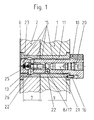
- the fitting system bolt A or B, 3 or 4 shown in Fig. 1 in the fitted and joined position consists essentially of the pre-positioning mandrel 6, equipped with a truncated cone-like chamfer, from the neck-like first positioning shaft 7, from a second positioning shaft 9, and from one Head part 10 and is received in the fitting sockets 11 and 13.
- At least one expanding adjusting element 8, designed as a radially movable ball 17, is arranged on the circumference of the positioning shaft 9.
- two or one axially directed fitting guide webs 15 are arranged symmetrically opposite the radially movable ball 17.
- the first positioning shaft 7 of the fitting system bolts A or B 3 or 4 is designed as a clamping shaft.
- the radially movable pressure balls 17 rest in axially displaced tension bevels 26 of the adapter sleeve 13, a low tension being generated by the small contact angle.
- Axial bypasse is included in the Passisystzembolzen A and B, 3 and 4, a linear-way pressure setting. It consists of the individual elements lying against one another on the end face, a screw-actuated linear drive 20, a coupling member 21, conical deflection members 22, movable in opposite directions, and a relaxation compression spring 23. Due to the linear displacement pressure setting, the pressure balls 17 lie on the inner walls of the fitting bushes 13 as well as the fitting guide webs 15 in the fit position, so that they are adjusted by point, line and surface pressures.
- the fitting system bolt A or B, 3 or 4 is secured against rotation via its head part 10 with a pin-like anti-rotation element 16 in the predetermined position in the quick-fit system.
- the pass guide webs 15 are each two raised guide and contact points, in each of the Fitting bushes 11 and 13 projecting.
- the fitting system bolts A and B, 3 and 4 is the upper one and front machine component 1 with the lower and rear machine component 2 fit and firmly connected.
- the fitting system bolt A and B, 3 and 4 shown in FIG. 1 is in the fitting holes 12 and 14 the machine components 1 and 2 recorded, adjusted, precisely fitting and firmly connected.
- Characteristic of the fitting system bolt A, 3 shown in Fig. 3 are two circumferential axially parallel fitting guide webs 15, which approach each other at a right angle about the central axis forming, symmetrically opposite the pressure ball 17.
- Fit system bolts B, 4 a pass guide web 15 is arranged axially parallel. This is the pressure ball 17 opposite.
- a fitting system bolt A is shown, the expanding adjusting element as one hollow cylindrical pressure chamber 19, shown in Fig. 5, or as a hollow cylindrical three-part Pressure chamber 19, shown in Fig. 6, is formed.
- the pressure chamber 19 is easily deformable Plasticine filled.
- the screw accommodated in the pre-positioning mandrel 6 and designed as a screw Linear drive 20 the volume of the pressure chamber is reduced via a linearly moving plate. This causes the thin-walled socket part 18 to bulge in the first positioning shaft 7. This leads to an adjustment and tension of the fitting system bolt A in the inner wall of the fitting sleeve 13.
- Der Fitting system bolt A is with the second positioning shaft 9 in the upper and front machine component 1 recorded and anchored.
- the quick pass system shown as an example in FIG. 7 consists of a pass system bolt A, 3 a fitting system bolt B, 4 and two system bolts C, 5, for tensioning the joined Machine components 1 and 2, in triangular positions.
- the fitting system bolt A, 3 is for Fitting system bolt B, 4 aligned so that the two fitting guide webs 15 on the fitting system bolt A, 3rd forming a right angle around its central axis, arranged symmetrically to the connecting line 24 are.
- the fitting guide web 15 on the fitting system bolt B, 4 is at right angles to the connecting line 24 arranged.
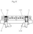
- Fig. 8 is an example by means of fitting system bolts A and B, 3 and 4 and system bolts C, 5 fit joined and connected by tension combination of a base plate Workpiece clamping device 27 shown with a pallet 28 of a drilling-milling machining center.
- a base plate 27 In the base plate 27 are fitting bushings 11 and in the pallet 28 fitting bushings 13 are introduced.
- the workpiece clamping device shown in simplified form in FIG. 9, consists of a machine component 1 designed as a double-angle clamping body, in the clamping wall of which machine components 2 designed as clamping plates are fitted and clamped with a precise fit.
- the fitting system bolts A and B, 3 and 4 are dimensioned longer than the wall thickness of the clamping wall and have pre-positioning mandrels 6 and positioning shafts 7 with radially directed adjusting elements 8 at both ends.
- the two clamping plates on the clamping wall are tensioned using system bolts C, 5.
- System bolt C Pre-positioning mandrel 7. first positioning 8th.
Landscapes
- Engineering & Computer Science (AREA)
- Mechanical Engineering (AREA)
- Jigs For Machine Tools (AREA)
- Clamps And Clips (AREA)
- Circuits Of Receivers In General (AREA)
- Stereo-Broadcasting Methods (AREA)
- Communication Control (AREA)
Abstract
Das radial gerichtet, expandierende Justierelement wird über einen Linearantrieb (20) schraub - und /oder hydraulisch betätigt.
Description
So werden nach DIN 6348 bei schnellspannenden Bohrvorrichtungen Auflageplatten für die Werkstücke auf den Vorrichtungskörpern der Bohrvorrichtungen mittels Stiftaufnahmen genau positioniert und auf dem Vorrichtungskörper verschraubt. Dafür steht jeweils ein runder Paßstift und ein abgeflachter Paßstift zur Verfügung. Die Bohrplatten der gleichen Bohrvorrichtungen werden von den Führungssäulen aufgenommen und bewegt. Dafür stehen zwei Führungssäulen zur Verfügung, eine runde Führungsäulenaufnahme und eine abgeflachte Führungsäulenaufnahme. Der abgeflachte Paßstift ermöglicht ebenso wie die abgeflachte Führungssäulenaufnahme einen eng begrenzten Ausgleich unterschiedlicher Abstandmaße der Bohrungen in der Auflageplatte bzw. in der Bohrplatte gegenüber dem Bolzenabstandsmaß bzw. dem Führungssäulenabstandsmaß der Bohrvorrichtung. Der runde Bolzen bzw. die runde Führungssäulenaufnahme sichern gleichzeitig eine mittengenaue Plattenjustierung in den zugeordneten Bohrungen.
Dabei bedingen aber die Toleranzüberschneidungen oder die Toleranzüberschreitungen beider Abstandsmaße Situationen die ein paßgenaues wiederholbares Fügen erschweren und verzögern oder entsprechende Nachjustierungen erforderlich werden lassen. Kennzeichnend für diese genormten Lösungen ist, daß eine Verschraubung der gefügten Bauteile Stand der Technik ist.
Die mit der Erfindung erzielten Vorteile bestehen insbesondere darin, daß nach einer paßgenauen Fügung einerseits dem Paßsystembolzen A eine genaue Mittenjustierung und dem Paßsystembolzen B eine genaue Umfangsjustierung und anderseits durch an beiden an deren Umfang angeordneten radialgerichteten expandierenden Justierelemente geringe Abstandsmaßunterschiede ausgleichbar sind. Das Justierprinzip ist als eine Linear-, Weg-, Druckeinstellung körperlich in die Paßsystembolzen A und B integriert. Die Spannung der gefügten miteinander verbundenen Maschinenbauteile erfolgt durch den Klemmschaft an den Paßsystembolzen oder zusätzlich durch mindestens einen Systembolzen C.
- einer Optimierung beim Ausgleich etwas größerer Abstandsmaßunterschiede der Paßbolzen gegenüber den Aufnahmebohrungen der zu fügenden Maschinenbauteile
- einer ergänzenden Nutzung der Paßsystembolzen als Klemm- oder Spannbolzen um einen oder mehrere gesonderte Klemm- und Spannbolzen in der Art eines Systembolzens C aus Gründen des Raumbedarfs entbehren zu können.
- einer beidseitigen Nutzung der Enden von Paßsystembolzen, die z.B. in Spannwänden von Aufspannkörpern angeordnet sind
- einer Optimierung der Positionierung der Paßsystembolzen in dem einer Flächen oder Linienanlage der Paßführungsstege durch eine Punktanlage in den Aufnahme Bohrungen der zu fügenden Maschinenbauteile ersetzbar ist.
Es zeigen
- Fig. 1
- einen gefügten Paßsystembolzen A oder B mit Paßbuchsen, im Mittenschnitt
- Fig. 2
- einen gefügten Paßsystembolzen A oder B
- Fig. 3
- eine Seitenansicht in Richtung A des Paßsystembolzens A
- Fig. 4
- eine Seitenansicht in Richtung A des Paßsystembolzen B
- Fig. 5
- einen Paßsystembolzen mit auswölbenden Buchsenteil, im Mittenschnitt
- Fig. 6
- einen Paßsystembolzen mit mehreren Druckkammern im auswölbenden Buchsenteil, im Mittenschnitt
- Fig. 7
- eine paßgenaue Fügung mittels Schnell-Pass-System, in der Draufsicht
- Fig. 8
- eine paßgenaue Fügung einer Grundplatte, einer Werkstückeinspannvorrichtung auf einer Palette, im Teilschnitt
- Fig. 9
- eine paßgenaue Fügung von Spannplatten beidseitig an der Mittenwand eines Aufspannkörpers, in vereinfachter Darstellung
Durch die Linear- Weg- Druckeinstellung bedingt liegen die Druckkugeln 17 an den Innenwandungen der Paßbuchsen 13 ebenso wie die Paßführungsstege 15 in Passungsstellung an, sodaß sie durch Punkt-, Linien- und Flächenpressungen justiert sind. Dabei ist der Paßsystembolzen A oder B, 3 oder 4, über sein Kopfteil 10 mit einem stiftartigen Verdrehsicherungselement 16 in der vorgegeben Position im Schnell-Pass-System gegen Verdrehung gesichert.
| Bezugszeichenliste | |
| Pos.-Nr. | |
| 1. | oberes oder vorderes Maschinenbauteil |
| 2. | unteres oder hinteres Maschinenbauteil |
| 3. | Paßsystembolzen A |
| 4. | Paßsystembolzen B |
| 5. | Systembolzen C |
| 6. | Vorpositionierdorn |
| 7. | erster Positionierschaft |
| 8. | expandierendes Justierelement |
| 9. | zweiter Positionierschaft |
| 10. | Kopfteil |
| 11. | ( obere oder vordere ) Paßbuchse |
| 12. | ( obere oder vordere ) Paßbohrung |
| 13. | ( untere oder hintere ) Paßbuchse |
| 14. | ( untere oder hintere ) Paßbohrung |
| 15. | Paßführungssteg |
| 16. | Verdrehsicherungselement |
| 17. | Druckkugel |
| 18. | Buchsenteil |
| 19. | Druckkammer |
| 20. | Linearantrieb |
| 21. | Koppelglied |
| 22. | Ablenkglied |
| 23. | Entspannungs - Druckfeder |
| 24. | Verbindunglinie ( zwischen Paßsystembolzen A und B ) |
| 25. | Klemmschaft ( an Paßbolzen A und B ) |
| 26. | Spannschrägen |
| 27. | Grundplatte einer Werkstückeinspannvorrichtung |
| 28. | Palette |
Claims (6)
- Schnell-Pass-System für ein paßgenaues wiederholbares Fügen von mindestens zwei mit jeweils einer ebenen Fläche plan aneinander liegender Bauteile von Maschinen und anderen Industriegütern oder aneinander liegender Werkstücke, in definierter Lage zueinander angeordnet, beispielsweise als eine Schnittstelle zwischen Werkstückeinspannvorrichtungen und Paletten von Bohr-, Fräs-, Bearbeitungszentren ausgebildet mit mindestens jeweils zwei in einem bestimmten Abstand zueinander angeordnete Paßsystembolzen in mindestens zwei adäquat parallel angeordnete und dimensionierte Paßbohrungen oder Paßbuchsen ragend, eingepaßt, justiert und die gefügten Bauteile von mindestens einem dritten Systembolzen in der eingepaßten Fügeposition befestigt sind,
dadurch gekennzeichnet,daß jeder der Paßsystembolzen A und B (3 und 4)
aus einem Vorpositionierdorn (6), mit kegelstumpfartiger Anfasung,
aus einem halsartigem ersten Positionierschaft (7), an dessen Umfang mindestens ein radialgerichtet expandierendes Justierelement (8) angeordnet ist, welches axial einstellbar gemeinsam mit zwei oder einem am Umfang der Paßsystembolzen A und B axial gerichtet verlaufenden Paßführungsstegen (15) in einer Mittenlage in einer unteren oder hinteren Paßbohrung (14) oder Paßbuchse (13) des unteren oder hinteren zu fügenden Maschinenteiles (2) eingepaßt, positioniert ist,
aus einem zweiten Positionierschaft (9) an dessen Umfang der eine oder die zwei Paßführungsstege (15), vom ersten Positionierschaft (7) her fortgeführt, in einer oberen oder vorderen Paßbohrung (12) oder Paßbuchse (11) des oberen oder vorderen Maschinenteiles (1) eingepaßt, positioniert sind und aus einem Kopfteil (10) größeren Durchmessers besteht, das mit einem Verdrehsicherungelement (16) ausgestattet ist, gebildet wird, unddaß das expandierende Justierelement (8) der Paßsystembolzen A und B (3 und 4) wahlweise als radialbewegliche Druckkugel (17), symmetrisch den Paßführungsstegen (15) am Umfang des Paßsystembolzens A oder B gegenüberliegend,
als radialgerichtet auswölbender Buchsenteil (18), aus flexiblen leicht verformbaren Werkstoff bestehend,
als leicht verformbare Spannknete, die in zylindrischen Druckkammern (19), deren Wände am Umfang des Paßsystembolzen A (3) radial gerichtet elastisch auswölbbar sind, aufgenommen ist.
ausgebildet ist und mittels einer axial gerichtet in den Paßsystembolzen A und B (3 und 4)
aufgenommenen Linear-, Weg-, Druckeinstellung
aus einem Linearantrieb (20), schraub- und / oder hydraulisch betätigt,
aus einem Koppelglied (21)
aus einem kugel- oder kegelförmigen Ablenkglied (22)
und aus einer Entspannungs-Druckfeder (23),
stirnseitig aneinanderliegend, besteht und
radialbeweglich unter Druck, an den Innenwandungen von Paßbohrungen (14) oder Paßbuchsen (13) anliegen, die Passungsstellung mittels Punkt-, Linien- oder Flächenpressungen justiert ist - Schnell-Pass-System nach Anspruch 1,
dadurch gekennzeichnet,daß ein Paßsystembolzen A (3) mit zwei Paßführungsstegen (15) und ein Paßsystembolzen B (4) mit einem Paßführungssteg (15) ausgestattet, sind und gemeinsam mit jeweils einem Systembolzen C (5) in einer Dreieckslage zueinander angeordnet sind, wobei die zwei Paßführungsstege (15) am Paßsystembolzen A (3) in einer Mittenlage der Paßbohrung (12, 14) oder der Paßbuchse (11, 13), einen rechten Winkel um die Mittenachse des Paßsystembolzen A (3) bildend, symmetrisch zur Verbindungslinie (24) beider Paßsystembolzen A und B (3 und 4) angeordnet, in Richtung des Paßsystembolzens B (4) in einer tolerenzausgleichenden Umfangslage der Paßbohrung (12, 14) oder der Paßbuchse (11, 13) angeordnet unddaß der Paßführungssteg (15) am Paßsystembolzen B (4) im rechten Winkel zur Verbindungslinie (24) beider Verbindungsbolzen A und B ( 3 und 4) angeordnet ist. - Schnell-Pass-System nach Anspruch 1,
dadurch gekennzeichnet,daß wahlweise ein Paßsystembolzen A oder B (3 oder 4) mit einem Klemmschaft (25) einstückig verbunden ist, wobei der nach dem Vorpositionierdorn (6) angeordnete Positionierschaft (7) mit mindestens einer radial beweglichen Druckkugel (23) in entsprechenden Spannschrägen (26) an der Innenwand einer gegen Axial- und Verdrehbewegung in dem unteren oder hinteren Maschinenteil (2) gesicherten Paßbuchse (13) befestigt und durch eine definierte winklig gegenüber der Axiallage der Druckkugel (23) in Einführungsrichtung axial versetzt angeordnete Spannschräge (26) eine Niederzugspannung erzeugbar ist. - Schnell-Pass-System nach Anspruch 1 bis 3,
dadurch gekennzeichnet,daß, die Paßsystembolzen A und B (3 und 4) in Paßbohrungen (12 ) oder in Paßbuchsen (11) in dem oberen oder vorderen Maschinenteil (1) verankert sind und daß jeder der Paßsystembolzen beidseitig mit Vorpositionierdornen (6) und an den Positionierschäften (7) mit radialgerichtet expandierenden Justierelementen ausgestattet sind. - Schnell-Pass-System nach Anspruch 1 und 3,
dadurch gekennzeichnet,daß wahlweise der schraub- und / oder hydraulisch betätigte Linearantrieb (20) mit einer der Paßbuchsen (11 oder 13) beweglich funktionsverbunden ist - Schnell-Pass-System nach Anspruch 1 bis 5,
dadurch gekennzeichnet,daß die Paßführungsstege (15) wahlweise als erhabene Führungs- und Anlagepunkte ausgebildet sind, wobei vorzugsweise je zwei Führungs- und Anlagepunkte an den Innenwandungen jeder Paßbohrung (12, 14) oder jeder Paßbuchse (11, 13) anliegen
Applications Claiming Priority (2)
| Application Number | Priority Date | Filing Date | Title |
|---|---|---|---|
| DE19739460 | 1997-09-03 | ||
| DE19739460A DE19739460C1 (de) | 1997-09-03 | 1997-09-03 | Schnell-Paß-System für Bauteile von Werkzeugmaschinen |
Publications (3)
| Publication Number | Publication Date |
|---|---|
| EP0900628A2 true EP0900628A2 (de) | 1999-03-10 |
| EP0900628A3 EP0900628A3 (de) | 2000-12-20 |
| EP0900628B1 EP0900628B1 (de) | 2003-03-05 |
Family
ID=7841712
Family Applications (1)
| Application Number | Title | Priority Date | Filing Date |
|---|---|---|---|
| EP98116563A Expired - Lifetime EP0900628B1 (de) | 1997-09-03 | 1998-09-02 | Schnell-Pass-System |
Country Status (3)
| Country | Link |
|---|---|
| EP (1) | EP0900628B1 (de) |
| AT (1) | ATE233637T1 (de) |
| DE (2) | DE19739460C1 (de) |
Cited By (2)
| Publication number | Priority date | Publication date | Assignee | Title |
|---|---|---|---|---|
| CN104625871A (zh) * | 2015-01-28 | 2015-05-20 | 黄昌镜 | 分度夹具 |
| CN114131398A (zh) * | 2021-12-23 | 2022-03-04 | 北京新风航天装备有限公司 | 一种梯形十字键槽定位的高精度快换加工工装及加工方法 |
Families Citing this family (2)
| Publication number | Priority date | Publication date | Assignee | Title |
|---|---|---|---|---|
| DE19826328C1 (de) * | 1997-09-03 | 1999-11-25 | Hohenstein Vorrichtungsbau | Schnell-Paß-System für Bauteile von Werkzeugmaschinen |
| DE10312192B3 (de) * | 2003-03-19 | 2004-08-05 | Hohenstein Vorrichtungsbau Und Spannsysteme Gmbh | System-Niederzugspanner |
Family Cites Families (8)
| Publication number | Priority date | Publication date | Assignee | Title |
|---|---|---|---|---|
| US2707419A (en) * | 1953-08-19 | 1955-05-03 | Jergens Tool Specialty Company | Means for locating fixture plates with respect to the beds or platens of machine tools |
| US4500079A (en) * | 1984-01-30 | 1985-02-19 | General Dynamics Corporation/Convair Div. | Removable and replaceable locating pin for locating a workpiece on a sub-plate for machining |
| US4645391A (en) * | 1985-05-17 | 1987-02-24 | Fmc Corporation | Work set up method and apparatus |
| DE3801654A1 (de) * | 1988-01-21 | 1989-07-27 | Schunk Fritz Gmbh | Ausrichtsystem |
| DE3919077C1 (de) * | 1989-06-10 | 1990-07-26 | Erowa Ag, Reinach, Ch | |
| DE3929931A1 (de) * | 1989-09-08 | 1991-03-14 | Heckler & Koch Gmbh | Justiervorrichtung |
| DE4135418A1 (de) * | 1991-10-26 | 1993-05-27 | Emil Stark Gmbh | Spannvorrichtung zum spannen einer aufspannplatte auf einer traegerplatte fuer bearbeitungsmaschinen |
| DE4307342C2 (de) * | 1993-03-09 | 1994-12-08 | Erowa Ag | Einrichtung zum positionsdefinierten Aufspannen eines Werkstücks am Arbeitsplatz einer Bearbeitungsmaschine |
-
1997
- 1997-09-03 DE DE19739460A patent/DE19739460C1/de not_active Expired - Fee Related
-
1998
- 1998-09-02 AT AT98116563T patent/ATE233637T1/de not_active IP Right Cessation
- 1998-09-02 DE DE59807363T patent/DE59807363D1/de not_active Expired - Fee Related
- 1998-09-02 EP EP98116563A patent/EP0900628B1/de not_active Expired - Lifetime
Cited By (2)
| Publication number | Priority date | Publication date | Assignee | Title |
|---|---|---|---|---|
| CN104625871A (zh) * | 2015-01-28 | 2015-05-20 | 黄昌镜 | 分度夹具 |
| CN114131398A (zh) * | 2021-12-23 | 2022-03-04 | 北京新风航天装备有限公司 | 一种梯形十字键槽定位的高精度快换加工工装及加工方法 |
Also Published As
| Publication number | Publication date |
|---|---|
| EP0900628B1 (de) | 2003-03-05 |
| DE59807363D1 (de) | 2003-04-10 |
| ATE233637T1 (de) | 2003-03-15 |
| EP0900628A3 (de) | 2000-12-20 |
| DE19739460C1 (de) | 1999-02-11 |
Similar Documents
| Publication | Publication Date | Title |
|---|---|---|
| DE10155077B4 (de) | Wiederholgenaue Spanneinrichtung | |
| EP1321221B1 (de) | Spanneinrichtung mit einem Spannfutter und einem lösbar daran fixierbaren Werkstückträger | |
| EP2134490B1 (de) | Werkzeughalter | |
| EP3983169B1 (de) | Spannvorrichtung und werkstückhaltevorrichtung mit einer spannvorrichtung | |
| EP1595641B1 (de) | Spanneinrichtung mit einem Spannfutter und einer lösbar daran fixierbaren Palette | |
| EP2105226B2 (de) | Magnetspannfutter | |
| EP0753368B1 (de) | Spannvorrichtung zum genauen gegenseitigen Fixieren zweier Bauteile | |
| CH716410B1 (de) | Spanneinrichtung mit einem Spannfutter und einem lösbar daran fixierbaren Werkstückträger. | |
| EP3263274A1 (de) | Spanneinrichtung sowie spannsystem | |
| EP4194141A1 (de) | Spanneinrichtung | |
| EP3219437A1 (de) | Werkstückhaltevorrichtung und verfahren zur bestückung einer werkstückhaltevorrichtung mit einem werkstück | |
| EP2918379A1 (de) | Kupplungsvorrichtung für ein Handhabungsgerät | |
| EP0450383A1 (de) | Zentrierende Spannvorrichtung | |
| EP3616831B1 (de) | Spannvorrichtung | |
| EP0365557A1 (de) | Positioniereinrichtung und deren verwendung. | |
| EP0287777B1 (de) | Vorrichtung zur Halterung von Werkzeugen oder Werkstücken, die einen Zylindrischen Schaft aufweisen | |
| DE19917146A1 (de) | Nullpunktspannsystem | |
| EP0870580B1 (de) | Spannstock | |
| EP2177296B1 (de) | Dehnspanneinrichtung | |
| DE102014001963B4 (de) | Spannvorrichtung zum reproduzierbar, lagengenauen Festspannen von Werkstücken | |
| DE19739460C1 (de) | Schnell-Paß-System für Bauteile von Werkzeugmaschinen | |
| DE4202989C2 (de) | Flexibles Vorrichtungssystem in modularer Bauweise | |
| DE19826328C1 (de) | Schnell-Paß-System für Bauteile von Werkzeugmaschinen | |
| DE202004018168U1 (de) | Aus einer Spannvorrichtung und einem Werkstückträger gebildete Einheit | |
| DE19756215C2 (de) | Schnell-Paß-System für Bauteile von Werkzeugmaschinen |
Legal Events
| Date | Code | Title | Description |
|---|---|---|---|
| PUAI | Public reference made under article 153(3) epc to a published international application that has entered the european phase |
Free format text: ORIGINAL CODE: 0009012 |
|
| AK | Designated contracting states |
Kind code of ref document: A2 Designated state(s): AT CH DE ES FR GB IT LI |
|
| AX | Request for extension of the european patent |
Free format text: AL;LT;LV;MK;RO;SI |
|
| 17P | Request for examination filed |
Effective date: 19990719 |
|
| PUAL | Search report despatched |
Free format text: ORIGINAL CODE: 0009013 |
|
| AK | Designated contracting states |
Kind code of ref document: A3 Designated state(s): AT BE CH CY DE DK ES FI FR GB GR IE IT LI LU MC NL PT SE |
|
| AX | Request for extension of the european patent |
Free format text: AL;LT;LV;MK;RO;SI |
|
| RIC1 | Information provided on ipc code assigned before grant |
Free format text: 7B 23Q 16/00 A, 7F 16B 21/10 B, 7B 23Q 7/14 B, 7F 16B 21/16 B, 7B 23Q 3/18 B |
|
| AKX | Designation fees paid |
Free format text: AT CH DE ES FR GB IT LI |
|
| 17Q | First examination report despatched |
Effective date: 20020422 |
|
| GRAH | Despatch of communication of intention to grant a patent |
Free format text: ORIGINAL CODE: EPIDOS IGRA |
|
| GRAH | Despatch of communication of intention to grant a patent |
Free format text: ORIGINAL CODE: EPIDOS IGRA |
|
| GRAA | (expected) grant |
Free format text: ORIGINAL CODE: 0009210 |
|
| AK | Designated contracting states |
Designated state(s): AT CH DE ES FR GB IT LI |
|
| PG25 | Lapsed in a contracting state [announced via postgrant information from national office to epo] |
Ref country code: IT Free format text: LAPSE BECAUSE OF FAILURE TO SUBMIT A TRANSLATION OF THE DESCRIPTION OR TO PAY THE FEE WITHIN THE PRE;WARNING: LAPSES OF ITALIAN PATENTS WITH EFFECTIVE DATE BEFORE 2007 MAY HAVE OCCURRED AT ANY TIME BEFORE 2007. THE CORRECT EFFECTIVE DATE MAY BE DIFFERENT FROM THE ONE RECORDED.SCRIBED TIME-LIMIT Effective date: 20030305 |
|
| REG | Reference to a national code |
Ref country code: GB Ref legal event code: FG4D Free format text: NOT ENGLISH |
|
| REG | Reference to a national code |
Ref country code: CH Ref legal event code: EP |
|
| REF | Corresponds to: |
Ref document number: 59807363 Country of ref document: DE Date of ref document: 20030410 Kind code of ref document: P |
|
| GBT | Gb: translation of ep patent filed (gb section 77(6)(a)/1977) | ||
| PGFP | Annual fee paid to national office [announced via postgrant information from national office to epo] |
Ref country code: GB Payment date: 20030829 Year of fee payment: 6 Ref country code: DE Payment date: 20030829 Year of fee payment: 6 Ref country code: CH Payment date: 20030829 Year of fee payment: 6 |
|
| PGFP | Annual fee paid to national office [announced via postgrant information from national office to epo] |
Ref country code: FR Payment date: 20030901 Year of fee payment: 6 |
|
| PG25 | Lapsed in a contracting state [announced via postgrant information from national office to epo] |
Ref country code: AT Free format text: LAPSE BECAUSE OF NON-PAYMENT OF DUE FEES Effective date: 20030902 |
|
| PG25 | Lapsed in a contracting state [announced via postgrant information from national office to epo] |
Ref country code: ES Free format text: LAPSE BECAUSE OF FAILURE TO SUBMIT A TRANSLATION OF THE DESCRIPTION OR TO PAY THE FEE WITHIN THE PRESCRIBED TIME-LIMIT Effective date: 20030930 |
|
| ET | Fr: translation filed | ||
| PLBE | No opposition filed within time limit |
Free format text: ORIGINAL CODE: 0009261 |
|
| STAA | Information on the status of an ep patent application or granted ep patent |
Free format text: STATUS: NO OPPOSITION FILED WITHIN TIME LIMIT |
|
| 26N | No opposition filed |
Effective date: 20031208 |
|
| PG25 | Lapsed in a contracting state [announced via postgrant information from national office to epo] |
Ref country code: GB Free format text: LAPSE BECAUSE OF NON-PAYMENT OF DUE FEES Effective date: 20040902 |
|
| PG25 | Lapsed in a contracting state [announced via postgrant information from national office to epo] |
Ref country code: LI Free format text: LAPSE BECAUSE OF NON-PAYMENT OF DUE FEES Effective date: 20040930 Ref country code: CH Free format text: LAPSE BECAUSE OF NON-PAYMENT OF DUE FEES Effective date: 20040930 |
|
| PG25 | Lapsed in a contracting state [announced via postgrant information from national office to epo] |
Ref country code: DE Free format text: LAPSE BECAUSE OF NON-PAYMENT OF DUE FEES Effective date: 20050401 |
|
| GBPC | Gb: european patent ceased through non-payment of renewal fee |
Effective date: 20040902 |
|
| REG | Reference to a national code |
Ref country code: CH Ref legal event code: PL |
|
| PG25 | Lapsed in a contracting state [announced via postgrant information from national office to epo] |
Ref country code: FR Free format text: LAPSE BECAUSE OF NON-PAYMENT OF DUE FEES Effective date: 20050531 |
|
| REG | Reference to a national code |
Ref country code: FR Ref legal event code: ST |