EP0899799A2 - Jar can for secondary battery - Google Patents
Jar can for secondary battery Download PDFInfo
- Publication number
- EP0899799A2 EP0899799A2 EP98306791A EP98306791A EP0899799A2 EP 0899799 A2 EP0899799 A2 EP 0899799A2 EP 98306791 A EP98306791 A EP 98306791A EP 98306791 A EP98306791 A EP 98306791A EP 0899799 A2 EP0899799 A2 EP 0899799A2
- Authority
- EP
- European Patent Office
- Prior art keywords
- jar
- layer
- aluminum
- nickel
- thickness
- Prior art date
- Legal status (The legal status is an assumption and is not a legal conclusion. Google has not performed a legal analysis and makes no representation as to the accuracy of the status listed.)
- Granted
Links
Images


Classifications
-
- H—ELECTRICITY
- H01—ELECTRIC ELEMENTS
- H01M—PROCESSES OR MEANS, e.g. BATTERIES, FOR THE DIRECT CONVERSION OF CHEMICAL ENERGY INTO ELECTRICAL ENERGY
- H01M50/00—Constructional details or processes of manufacture of the non-active parts of electrochemical cells other than fuel cells, e.g. hybrid cells
- H01M50/10—Primary casings; Jackets or wrappings
- H01M50/116—Primary casings; Jackets or wrappings characterised by the material
- H01M50/124—Primary casings; Jackets or wrappings characterised by the material having a layered structure
-
- H—ELECTRICITY
- H01—ELECTRIC ELEMENTS
- H01M—PROCESSES OR MEANS, e.g. BATTERIES, FOR THE DIRECT CONVERSION OF CHEMICAL ENERGY INTO ELECTRICAL ENERGY
- H01M50/00—Constructional details or processes of manufacture of the non-active parts of electrochemical cells other than fuel cells, e.g. hybrid cells
- H01M50/10—Primary casings; Jackets or wrappings
- H01M50/116—Primary casings; Jackets or wrappings characterised by the material
- H01M50/117—Inorganic material
- H01M50/119—Metals
-
- H—ELECTRICITY
- H01—ELECTRIC ELEMENTS
- H01M—PROCESSES OR MEANS, e.g. BATTERIES, FOR THE DIRECT CONVERSION OF CHEMICAL ENERGY INTO ELECTRICAL ENERGY
- H01M50/00—Constructional details or processes of manufacture of the non-active parts of electrochemical cells other than fuel cells, e.g. hybrid cells
- H01M50/10—Primary casings; Jackets or wrappings
- H01M50/131—Primary casings; Jackets or wrappings characterised by physical properties, e.g. gas permeability, size or heat resistance
- H01M50/133—Thickness
-
- H—ELECTRICITY
- H01—ELECTRIC ELEMENTS
- H01M—PROCESSES OR MEANS, e.g. BATTERIES, FOR THE DIRECT CONVERSION OF CHEMICAL ENERGY INTO ELECTRICAL ENERGY
- H01M50/00—Constructional details or processes of manufacture of the non-active parts of electrochemical cells other than fuel cells, e.g. hybrid cells
- H01M50/10—Primary casings; Jackets or wrappings
- H01M50/102—Primary casings; Jackets or wrappings characterised by their shape or physical structure
- H01M50/103—Primary casings; Jackets or wrappings characterised by their shape or physical structure prismatic or rectangular
-
- Y—GENERAL TAGGING OF NEW TECHNOLOGICAL DEVELOPMENTS; GENERAL TAGGING OF CROSS-SECTIONAL TECHNOLOGIES SPANNING OVER SEVERAL SECTIONS OF THE IPC; TECHNICAL SUBJECTS COVERED BY FORMER USPC CROSS-REFERENCE ART COLLECTIONS [XRACs] AND DIGESTS
- Y02—TECHNOLOGIES OR APPLICATIONS FOR MITIGATION OR ADAPTATION AGAINST CLIMATE CHANGE
- Y02E—REDUCTION OF GREENHOUSE GAS [GHG] EMISSIONS, RELATED TO ENERGY GENERATION, TRANSMISSION OR DISTRIBUTION
- Y02E60/00—Enabling technologies; Technologies with a potential or indirect contribution to GHG emissions mitigation
- Y02E60/10—Energy storage using batteries
Definitions
- the present invention relates to a jar can for a secondary battery, and more particularly, it relates to a jar can for a secondary battery which is lightweight and attains high rigidity.
- the sealed batteries include a nickel-hydrogen storage battery, a lithium ion secondary battery and the like, for example.
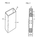
- a bottomed battery jar can (jar can) 13 of a nickel-hydrogen storage battery 1 has an open upper end.
- This jar can 13 stores a plate group 16 including a positive electrode 7, a positive lead tab 5, a negative electrode 11 and a separator 9.
- a valve element 4, a cap 2, a rivet 8, an insulating plate gasket 10, a washer 12 and a frame body 14 are provided above the plate group 16.
- a lid body 6 is provided on the upper end opening of the jar can 13, for electrically isolating the jar can 13 from the cap 2 through the insulating plate gasket 10.
- the jar can 13 is generally prepared from a nickel-plated steel sheet. In order to cope with recent weight reduction of apparatuses or the like, a jar can prepared from aluminum or an aluminum alloy is developed.
- a second exemplary conventional jar can for an angular sealed battery disclosed in Japanese Patent Laying-Open No. 6-52842 (1994) is now described.
- a bottomed angular jar can 51 has wider and narrower side surfaces 52 and 55 and an open upper end.
- This jar can 51 has been provided in order to suppress deformation resulting from increase in internal pressure, in particular. Therefore, the wider side surfaces 52 are larger in thickness than the narrower side surfaces 55.
- the first exemplary jar can 13 shown in Figs. 5B and 5C contains a positive electrode active material, a negative electrode active material and an electrolyte. Pressure is applied from the interior to the side and bottom surfaces of the jar can 13 due to generation of gas resulting from reaction between the active materials and the electrolyte or electrochemical reaction in charging of the battery 1 and swelling of the electrodes 7 and 11.
- an aluminum killed steel sheet (SPCE material under Japanese Industrial Standards) is employed as a nickel-plated steel sheet which is applied to a jar can.
- This SPCE material has a relatively large Young's modulus of about 20000 kgf/mm 2 . Therefore, the aforementioned swelling deformation can be suppressed in a specific range by setting the thickness of the SPCE material at about 0.4 mm.
- the jar can weighs about 7 g since the specific gravity of the SPCE material is about 7.8. Consequently, the jar can occupies about 30 to 40 % of the total weight of a battery to which the same is applied, leading to a problem in weight.
- the Young's modulus of a light metal such as aluminum or an aluminum alloy is about 7000 kgf/mm 2 . This value is about 1/3 of that of the SPCE material.
- the weight of the jar can is also increased. If the thickness is increased while keeping the outer dimensions unchanged, further, the volume in the jar can is reduced. Thus, the capacity of a battery to which the jar can is applied may be reduced.
- a material having a high Young's modulus is studied in relation to various materials of aluminum and aluminum alloys. In the present circumstances, however, a material having a high Young's modulus is inferior in moldability for deep drawing or the like and cannot provide a practical jar can.
- the second exemplary jar can 51 has been proposed in order to suppress swelling deformation, as described above.
- material sheets having portions of different thicknesses corresponding to the wider and narrower side surfaces are required. Therefore, the cost for the material sheets is so increased that the jar can cannot be economically obtained.
- the present invention has been proposed in order to solve the aforementioned problems, and an object thereof is to provide a lightweight jar can for a secondary battery having high rigidity, which can suppress swelling deformation and ensure a battery capacity.
- the present invention is directed to a bottomed jar can for a secondary battery, which comprises a first layer including a sheet of aluminum or an aluminum alloy and a second layer including a sheet of iron or a ferrous alloy.
- the first layer reduces the weight the jar can for a secondary battery, and the second layer attains high rigidity for suppressing swelling deformation. Consequently obtained is a lightweight jar can for a secondary battery having high rigidity.
- the second layer is formed on each side of the first layer.
- flexural rigidity per constant weight of the jar can for a secondary battery is most strengthened due to the formation of the second layer on each side of the first layer, since iron or the like forming the second layer has a higher Young's modulus as compared with aluminum or the like forming the first layer.
- the first layer is preferably formed on each side of the second layer.
- the second layer containing iron or a ferrous alloy keeps the rigidity of the jar can for a secondary battery
- the first layer containing aluminum or an aluminum alloy formed on each side of the second layer reduces the weight of the jar can for a secondary battery.
- the jar can for a secondary battery includes at least two clad units each formed by a set of the first and second layers.
- the first and second layers are properly combined with each other by forming the clad units in response to the use of the jar can. Consequently obtained is a desired jar can for a secondary battery making the best use of lightweightness and high rigidity.
- the first and second layers are at least 0.05 mm and not more than 0.6 mm in thickness respectively, and each clad unit formed by the set of the first and second layers is at least 0.1 mm and not more than 1.2 mm in thickness.
- the manufacturing cost is so increased that the jar can for a secondary battery is unpractical in cost. Further, it is difficult to work or handle the jar can for a secondary battery in this case. If the first and second layers are in excess of 0.6 mm in thickness, on the other hand, it is difficult to ensure an effective internal volume as well as a volume energy density of the battery and the jar can is unpractical. Therefore, the proper thickness of the clad unit is at least 0.1 mm and not more than 1.2 mm.
- a nickel-plated layer is formed on at least one surface of the second layer.
- the nickel-plated layer is at least 3 ⁇ m and not more than 5 ⁇ m in thickness.
- the nickel-plated layer is smaller than 3 ⁇ m in thickness, pin holes or the like are so readily caused in the nickel-plated layer that corrosion resistance may be deteriorated. If the nickel-plated layer is larger than 5 ⁇ m in thickness, on the other hand, the cost for nickel plating is increased to disadvantageously increase the manufacturing cost.
- the jar can for a secondary battery has a third layer containing nickel between the first and second layers as an intermediate layer.
- the bonding strength between the first and second layers is highly and stably maintained.
- the third layer is a nickel-plated layer of at least 3 ⁇ m and not more than 5 ⁇ m in thickness.
- the corrosion resistance is deteriorated if the nickel-plated layer is smaller than 3 ⁇ m in thickness, while the manufacturing cost is increased if the nickel-plated layer is larger than 5 ⁇ m in thickness.
- the jar can for a secondary battery has a substantially prismatic outer shape.
- the secondary battery can be efficiently stored in a limited space of a portable apparatus or the like.
- the present invention provides a jar can for a sealed secondary battery prepared from a clad (bonded) material (hereinafter referred to as "aluminum/iron clad”) formed by a sheet of aluminum or an aluminum alloy and a sheet of iron or a ferrous alloy.
- aluminum/iron clad a clad (bonded) material
- the aluminum/iron clad in place of the alternative of the sheet of aluminum or an aluminum alloy or the sheet of iron or a ferrous alloy, it is possible to provide an arbitrary jar can making the best use of excellent characteristics of the sheets of aluminum or an aluminum alloy and iron or a ferrous alloy by setting the thicknesses and the materials in optimum combination in response to the use of the jar can.
- the jar can must be increased in thickness in consideration of the strength if the same is prepared from only an aluminum material, while the weight of the jar can cannot be readily reduced due to limitation in molding on reduction of the thickness if the same is prepared only from a ferrous material.
- the inventive jar can employing the aluminum/iron clad can advantageously solve these problems.
- the sheet of aluminum or an aluminum alloy forming the aluminum/iron clad mainly contributes to weight reduction of the jar can, and has excellent moldability for deep drawing or the like.
- Such a material can be prepared from pure aluminum (No. 1000 level under JIS) or an aluminum alloy (No. 3000, 4000 or 5000 level under JIS) in response to the use of the jar can, and is economically obtainable at a low cost.
- the sheet of iron or a ferrous alloy forming the aluminum/iron clad mainly contributes to high rigidity of the jar can.
- the sheet of iron or the like has a function of suppressing swelling deformation resulting from the low Young's modulus of aluminum with a relatively small thickness.
- this material can be prepared from an aluminum killed steel sheet (SPCE) or a stainless steel sheet (SUS 304 or SUS 403), and is economically obtainable at a low cost.
- a clad unit consisting of two layers of the sheets of aluminum and iron generally is the minimum structural unit.
- the clad unit may have a three-layer structure of aluminum, iron and aluminum or iron, aluminum and iron. Two or more such clad units may be stacked with each other.
- the sheets of iron and aluminum of the jar can on the inner and outer sides of the battery respectively, it is possible to ensure corrosion resistance with respect to an electrolyte in high reliability due to presence of a nickel-plated layer of at least 3 ⁇ m and not more than 5 ⁇ m in thickness on a surface (inner surface) of the sheet of iron, similarly to the case of employing a conventional nickel-plated steel sheet. Since the aluminum sheet is positioned on the outer side, further, it is possible to readily assemble the overall jar can by laser welding or the like.
- the sheets of aluminum and iron of the jar can on the inner and outer sides of the battery respectively, on the other hand, it is effective if aluminum is not corrosion-resistant with respect to the electrolyte, e.g., provided on a positive electrode side of a lithium secondary battery, for example.
- the iron sheet is provided on the outer side of the jar can, further, the jar can is hard to damage and excellent in durability, while inexpensive caulking or the like can be provided for assembling of the overall jar can.
- the jar can of this structure is applied to an alkali storage battery, for example, and the temperature increases to about 60°C at the maximum due to electrochemical reaction or the like in charging thereof, bending stress resulting from the difference between the thermal expansion coefficients of aluminum and iron causes stress deforming side surfaces of the jar can inward, thereby suppressing swelling deformation following increase of the internal pressure of the jar can.
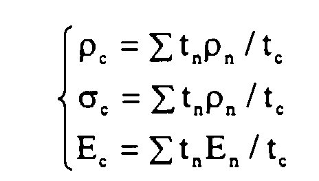
- the jar can has a two layers, three layers or more layers, the basic physical and mechanical properties thereof substantially coincide with values calculated by mixed rules with the properties and thicknesses of the respective layers forming the aluminum/iron clad.
- p represents specific gravity
- ⁇ represents tensile strength
- E represents a modulus of longitudinal elasticity (Young's modulus)
- t represents a sheet thickness
- c represents the aluminum/iron clad
- n represents the material forming each layer
- the aluminum/iron clad has three layers of iron, aluminum or iron or more layers and the iron layers having a higher Young's modulus are formed on the inner and outer sides of the battery, it is possible to maximize the flexural rigidity per constant weight of the jar can. This effect can be attained since the flexural rigidity of the aluminum/iron clad remarkably depends on the Young's modulus on its surfaces. Thus, a lightweight jar can having high rigidity can be obtained in this case.
- the jar can for a secondary battery according to the present invention includes that formed with a nickel-plated layer at least on one outer surface thereof.
- This nickel-plated layer is preferably at least 3 ⁇ m and not more than 5 ⁇ m in thickness. If the nickel-plated layer is smaller than 3 ⁇ m in thickness, pin holes or the like are so readily caused in the nickel-plated layer that the corrosion resistance may be deteriorated. If the nickel-plated layer is larger than 5 ⁇ m in thickness, on the other hand, the cost is disadvantageously increased due to costly nickel plating, although no remarkable problem arises in quality.
- a nickel layer as an intermediate layer on the bonding interface between the sheets of aluminum and iron of the jar can formed by the aluminum-iron clad having two or more layers, in order to highly maintain the bonding strength between the sheets of aluminum and iron.
- the bonding strength may be reduced or rendered heterogeneous.
- the aluminum/iron clad including the nickel-plated layer as an intermediate layer is prepared by forming the nickel-plated layer on the surface of aluminum and/or that of iron before bonding, and thereafter bonding the sheets of aluminum and iron to each other. Therefore, the bonding strength between the sheets of aluminum and iron is stable and the adhesion strength on the bonding interface of the aluminum/iron clad is entirely homogenized. This is inferred because an oxide layer on the nickel surface is not sufficiently strong.
- a commercially available nickel-plated steel sheet or the like can be employed as the material for the aluminum-iron clad, for example.
- This nickel-plated layer is properly at least 3 ⁇ m and not more than 5 ⁇ m in thickness.
- the corrosion resistance is deteriorated if the nickel-plated layer is smaller than 3 ⁇ m in thickness, while the manufacturing cost is increased if the nickel-plated layer is larger than 5 ⁇ m in thickness.
- the sheets of aluminum and iron forming the aluminum-iron clad are preferably in the range of at least 0.05 mm and not more than 0.6 mm in thickness respectively. If the sheets of aluminum and iron are less than 0.05 mm in thickness, the material cost is so increased that the jar can is unpractical in cost and handling such as working of the materials is difficult. These problems are practically solved when the sheets of iron and aluminum are at least 0.05 mm in thickness. If the sheets of aluminum and iron are in excess of 0.6 mm in thickness, on the other hand, it is difficult to ensure an effective internal volume as well as a volume energy density of the battery and the jar can is unpractical.
- the total thickness of the aluminum/iron clad is preferably at least 0.1 mm and not more than 1.2 mm.
- FIG. 1A to 1C show an upper surface and sections of a prismatic sealed nickel-hydrogen storage battery 1.
- Fig. 1D is an enlarged view of a part A shown in Fig. 1C.
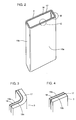
- Fig. 2 shows the appearance of the jar can 3 shown in Figs. 1A to 1D.
- Figs. 3 and 4 are enlarged views of parts B and C shown in Fig. 2 respectively.
- a sheet 17 of aluminum and a sheet 18 of iron are formed on outer and inner side surfaces of the jar can 3 respectively.
- a nickel layer 19a is formed on an inner surface of the iron sheet 18.
- Another nickel layer 19b is formed between the iron sheet 18 and the aluminum sheet 17.
- various materials and thicknesses are applied to such sheets 17 and 18 of aluminum and iron as shown in Table 1.
- components other than the jar can 3 are identical in structure to those of the sealed nickel-hydrogen storage battery 1 shown in Figs. 5A to 5C described with reference to the prior art, and hence identical members are denoted by the same reference numerals, to omit redundant description.
- a clad sheet of 100 by 100 mm having a thickness of 0.4 mm was prepared by diffusion-bonding a pure aluminum sheet (corresponding to A1050 under JIS) of 0.3 mm in thickness and an aluminum killed steel sheet of about 0.1 mm in thickness, having nickel-plated layers of about 4 ⁇ m in thickness on both surfaces, to each other.
- a pure aluminum sheet corresponding to A1050 under JIS
- an aluminum killed steel sheet of about 0.1 mm in thickness, having nickel-plated layers of about 4 ⁇ m in thickness on both surfaces, to each other.
- This clad sheet was deep-drawn for preparing a prismatic jar can for a nickel-hydrogen storage battery of 17 mm in width, 48 mm in height and 6 mm in thickness (17 by 48 by 6 mm) with the pure aluminum sheet and the aluminum killed steel sheet provided on outer and inner sides of the battery respectively.
- the clad sheet was so excellently deep-drawn that no defect such as cracking, creasing or peeling was recognized thereon.
- the weight of this jar can was about 3.3 g. It means that the weight was reduced by about 49 % as compared with a conventional jar can of 6.5 g in weight employing a nickel-plated steel sheet of 0.4 mm in thickness.
- the jar can 3 storing a positive electrode 7, a negative electrode 11, a separator 9 and an electrolyte (not shown) serving as generators was connected with a battery terminal through a lead wire, and thereafter a lid provided with a valve element 4 was mounted by laser welding for preparing a completely sealed secondary battery.
- the jar can occupied about 26 % of the total weight of the secondary battery.
- the weight of the jar was remarkably reduced as compared with that of a conventional jar can employing a nickel-plated steel sheet occupying about 40 % of the total thickness of a battery, to reduce the weight of the secondary battery as a result.
- the weight energy density of the secondary battery employing this jar can was 50 Wh/kg. It means that the weight energy density was improved by about 20 % as compared with that of 42 Wh/kg of the conventional battery.
- the thickness of the jar can was set at 0.4 mm similarly to that of the conventional one. Thus, it was impossible to improve an effective internal volume of the jar can and the volume energy density.
- the characteristics of the secondary battery to which this jar can was applied were evaluated and compared with those of a conventional battery. Charge/discharge characteristics, life and preservability of the secondary battery were substantially equivalent to those of the conventional battery. Further, swelling and deformation of the jar can resulting from increase of the internal pressure of the battery in charging were evaluated, to observe swelling on wider side surfaces of the jar can when the internal pressure was about 5 kg/cm 2 . However, this swelling was smaller than an abnormal level of 0.5 mm and caused no problem in practice.
- a clad sheet of 100 by 100 mm having a thickness of 0.6 mm was prepared by diffusion-bonding a sheet of an aluminum alloy (corresponding to A3003 under JIS) of 0.45 mm in thickness and an aluminum killed steel sheet of 0.15 mm in thickness, having nickel-plated layers of about 4 ⁇ m in mean thickness on both surfaces, to each other.
- an aluminum alloy corresponding to A3003 under JIS
- an aluminum killed steel sheet 0.15 mm in thickness
- This clad sheet was deep-drawn for preparing a prismatic jar can for a lithium ion storage battery of 40 by 48 by 8 mm with the aluminum alloy sheet and the aluminum killed steel sheet provided on outer and inner sides of the battery respectively.
- the clad sheet was so excellently deep-drawn that neither cracking, creasing, peeling nor remarkable damage of the nickel-plated layers was recognized thereon.
- the weight of this jar can was 9.3 g. It means that the weight was reduced by about 23 % with respect to the weight of about 12 g in a conventional jar can employing a nickel-plated steel sheet.
- a lid was provided on this jar can by caulking and pressure was intentionally applied to the interior of the jar can which was brought into a sealed state, for evaluating swelling and deformation thereof. Swelling was observed on wider side surfaces of the jar can when the internal pressure thereof was about 5 kg/mm 2 . However, this swelling was smaller than an abnormal level of 0.5 mm and caused no problem in practice.
- another jar can was prepared from only a sheet of an aluminum alloy (corresponding to A3003 under JIS), as shown on the row of No. 14 in Table 1.
- This jar can was electrically connected with a positive electrode. Due to the exclusive employment of the aluminum alloy, this jar can was further reduced in weight as compared with the aforementioned jar can employing the aluminum/iron clad sheet or the conventional jar can employing a nickel-plated steel sheet.
- a nonaqueous lithium battery can be reduced in thickness while keeping the strength and the weight unchanged according to the present invention.
- the jar can according to the present invention exhibits superior characteristics particularly when the same is applied to a prismatic lithium secondary battery.
- the proper thickness of the nickel-plated layers is at least 3 ⁇ m and not more than 5 ⁇ m. If the nickel-plated layers are smaller than 3 ⁇ m in thickness, pin holes or the like are readily caused in the nickel-plated layers to result in a problem in corrosion resistance or the like. If the nickel-plated layers are larger than 5 ⁇ m in thickness, on the other hand, the manufacturing cost is increased due to costly nickel plating, although no remarkable problem arises in quality.
- Jar cans were prepared under conditions shown in the rows of Nos. 3 to 12 in Table 1, and batteries to which the jar cans were applied were evaluated similarly to Examples 1 and 2.
- the aluminum/iron clad exhibited excellent moldability in deep drawing.
- swelling of the jar can was smaller than an abnormal level of 0.5 mm and caused no problem in practice.
- Table 1 shows numerical values of conventional jar cans employing only nickel-plated steel sheets and an aluminum sheet in the rows of Nos. 13 to 15.
- the jar cans Nos. 13 and 15 were relatively heavy, and the jar can No. 14 swelled and caused a problem in effective internal volume.
- swelling deformation of wider side surfaces of a jar can resulting from increase of its internal pressure can be reduced as compared with a conventional jar can employing only an aluminum sheet, while it is possible to reduce the weight of the jar can as compared with that of a jar can employing an iron sheet.
- a battery to which the inventive jar can is applied is miniature, lightweight and excellent in portability and causes less local deformation of its side surfaces despite its prismatic shape. Thus, it is possible to prevent such inconvenience that the battery cannot be taken out from an apparatus storing the same.
Landscapes
- Chemical & Material Sciences (AREA)
- Chemical Kinetics & Catalysis (AREA)
- Electrochemistry (AREA)
- General Chemical & Material Sciences (AREA)
- Inorganic Chemistry (AREA)
- Sealing Battery Cases Or Jackets (AREA)
Abstract
Description

Claims (10)
- A bottomed jar can (3) for a secondary battery, comprising:a first layer (17) including a sheet of aluminum or an aluminum alloy; anda second layer (18) including a sheet of iron or a ferrous alloy.
- A jar can in accordance with claim 1,
wherein said second layer (18) is formed on each side of said first layer (17). - A jar can in accordance with claim 1,
wherein said first layer (17) is formed on each side of said second layer (18). - A jar can in accordance with any one of the preceding claims, including at least two clad units each formed by a set of said first layer (17) and said second layer (18).
- A jar can in accordance with any one of the preceding claims, wherein said first layer (17) and said second layer (18) are at least 0.05 mm and not more than 0.6 mm in thickness respectively, and a clad unit formed by a set of said first layer (17) and said second layer (18) is at least 0.1 mm and not more than 1.2 mm in thickness.
- A jar can in accordance with any one of the preceding claims, wherein a nickel-plated layer (19a, 19b) is formed on at least one surface of said second layer (18).
- A jar can in accordance with claim 6,
wherein said nickel-plated layer (19a, 19b) is at least 3 µm and not more than 5 µm in thickness. - A jar can in accordance with any one of the preceding claims, further comprising a third layer (19a, 19b) containing nickel between said first layer (17) and said second layer (18) as an intermediate layer.
- A jar can in accordance with claim 8,
wherein said third layer (19a, 19b) is a nickel-plated layer of at least 3 µm and not more than 5 µm in thickness. - A jar can in accordance with any one of the preceding claims, having a substantially prismatic outer shape.
Applications Claiming Priority (6)
| Application Number | Priority Date | Filing Date | Title |
|---|---|---|---|
| JP23484297 | 1997-08-29 | ||
| JP234842/97 | 1997-08-29 | ||
| JP23484297 | 1997-08-29 | ||
| JP206687/98 | 1998-07-22 | ||
| JP20668798 | 1998-07-22 | ||
| JP20668798A JP3724955B2 (en) | 1997-08-29 | 1998-07-22 | Battery case for secondary battery |
Publications (3)
| Publication Number | Publication Date |
|---|---|
| EP0899799A2 true EP0899799A2 (en) | 1999-03-03 |
| EP0899799A3 EP0899799A3 (en) | 2000-04-26 |
| EP0899799B1 EP0899799B1 (en) | 2007-03-28 |
Family
ID=26515795
Family Applications (1)
| Application Number | Title | Priority Date | Filing Date |
|---|---|---|---|
| EP98306791A Expired - Lifetime EP0899799B1 (en) | 1997-08-29 | 1998-08-25 | Jar can for secondary battery |
Country Status (5)
| Country | Link |
|---|---|
| US (1) | US6127064A (en) |
| EP (1) | EP0899799B1 (en) |
| JP (1) | JP3724955B2 (en) |
| CN (1) | CN1156036C (en) |
| DE (1) | DE69837421T2 (en) |
Cited By (2)
| Publication number | Priority date | Publication date | Assignee | Title |
|---|---|---|---|---|
| EP1453123A1 (en) * | 2002-12-27 | 2004-09-01 | Samsung SDI Co., Ltd. | Secondary battery and manufacturing method thereof |
| WO2022101062A1 (en) * | 2020-11-11 | 2022-05-19 | Fraunhofer-Gesellschaft zur Förderung der angewandten Forschung e.V. | Battery cell, housing of such a battery cell, battery having a multiplicity of such battery cells, and method for producing such a housing |
Families Citing this family (25)
| Publication number | Priority date | Publication date | Assignee | Title |
|---|---|---|---|---|
| JP2000090893A (en) * | 1998-09-17 | 2000-03-31 | Japan Storage Battery Co Ltd | Battery and method for manufacturing battery |
| US6716554B2 (en) * | 1999-04-08 | 2004-04-06 | Quallion Llc | Battery case, cover, and feedthrough |
| US6554178B1 (en) * | 1999-04-08 | 2003-04-29 | Quallion Llc | Battery case feedthrough |
| EP1202360A4 (en) * | 1999-05-07 | 2004-09-22 | Matsushita Electric Industrial Co Ltd | RECTANGULAR CELL CONTAINER AND PRODUCTION METHOD THEREFOR |
| USD462938S1 (en) | 2000-03-31 | 2002-09-17 | David M. Revak | Jar for industrial battery |
| JP2001313008A (en) * | 2000-04-28 | 2001-11-09 | Matsushita Electric Ind Co Ltd | Battery can, method of manufacturing the same, and battery |
| JP4543710B2 (en) * | 2004-03-11 | 2010-09-15 | 日産自動車株式会社 | Assembled battery |
| JP3742422B1 (en) * | 2005-03-17 | 2006-02-01 | 日立マクセル株式会社 | Flat battery |
| KR100648731B1 (en) * | 2005-03-21 | 2006-11-23 | 삼성에스디아이 주식회사 | Secondary Battery and Manufacturing Method Thereof |
| CN101305481B (en) * | 2005-09-02 | 2011-01-12 | A123系统公司 | Battery cell design and method of its construction |
| JP2007087704A (en) * | 2005-09-21 | 2007-04-05 | Hitachi Vehicle Energy Ltd | Nonaqueous electrolyte secondary battery |
| ATE556461T1 (en) * | 2006-02-17 | 2012-05-15 | Emw Energy Co Ltd | CYLINDRICAL ZINC-AIR CELL AND PRODUCTION METHOD THEREOF |
| JP5250466B2 (en) * | 2009-03-31 | 2013-07-31 | 日立ビークルエナジー株式会社 | Non-aqueous electrolyte secondary battery and lithium secondary battery |
| US7736799B1 (en) * | 2009-07-17 | 2010-06-15 | Tesla Motors, Inc. | Method and apparatus for maintaining cell wall integrity during thermal runaway using an outer layer of intumescent material |
| US8263254B2 (en) * | 2009-07-17 | 2012-09-11 | Tesla Motors, Inc. | Cell with an outer layer of intumescent material |
| US8304108B2 (en) | 2009-07-17 | 2012-11-06 | Tesla Motors, Inc. | Method and apparatus for maintaining cell wall integrity using a high yield strength outer sleeve |
| KR20150068759A (en) * | 2013-12-12 | 2015-06-22 | 삼성에스디아이 주식회사 | Rechargeable battery |
| EP3085499A1 (en) * | 2015-04-24 | 2016-10-26 | HILTI Aktiengesellschaft | Tool battery protection shell |
| KR102143626B1 (en) * | 2017-11-14 | 2020-08-11 | 삼성에스디아이 주식회사 | Secondary |
| KR101890844B1 (en) * | 2017-11-24 | 2018-08-22 | 주식회사 리베스트 | An electrode assembly with improved safety in use by structure of outermost electrodes and material of current collectors, and lithium ion battery with the electrode assembly |
| DE102018108240A1 (en) * | 2018-04-06 | 2019-10-10 | Alinox Ag | A method of manufacturing a metal plate with an embedded temperature sensor, and metal plate produced thereafter |
| CN112103566A (en) * | 2020-10-20 | 2020-12-18 | 天津市捷威动力工业有限公司 | Method for manufacturing lithium ion battery by using gel diaphragm |
| DE212021000568U1 (en) * | 2021-06-28 | 2024-03-06 | Hefei Gotion High-Tech Power Energy Co., Ltd. | Cylindrical battery cell and battery |
| DE202022104195U1 (en) | 2022-07-25 | 2022-08-02 | Wickeder Westfalenstahl Gmbh | Housing for an electronic element, preferably a battery cell or a capacitor |
| EP4345959A1 (en) | 2022-09-29 | 2024-04-03 | Volocopter GmbH | Method of producing an encapsulated battery cell |
Family Cites Families (25)
| Publication number | Priority date | Publication date | Assignee | Title |
|---|---|---|---|---|
| US4216275A (en) * | 1978-06-13 | 1980-08-05 | Brown, Boveri & Cie Ag | Electrochemical storage cell or battery |
| JPS5946756A (en) * | 1982-09-09 | 1984-03-16 | Matsushita Electric Ind Co Ltd | alkaline battery |
| JPS63102158A (en) * | 1986-10-20 | 1988-05-07 | Matsushita Electric Ind Co Ltd | organic electrolyte battery |
| JPS63252353A (en) * | 1987-04-08 | 1988-10-19 | Matsushita Electric Ind Co Ltd | Small organic electrolyte battery |
| JPH0649933B2 (en) * | 1987-09-18 | 1994-06-29 | 日本鋼管株式会社 | Plated steel plate for cans |
| JPH03134949A (en) * | 1989-10-19 | 1991-06-07 | Matsushita Electric Ind Co Ltd | small lithium battery |
| JPH0574483A (en) * | 1991-09-11 | 1993-03-26 | Yuasa Corp | Manufacture of sealed secondary battery |
| JPH0574484A (en) * | 1991-09-11 | 1993-03-26 | Yuasa Corp | Manufacture of sealed secondary battery |
| JPH05174873A (en) * | 1991-12-24 | 1993-07-13 | Sanyo Electric Co Ltd | Nonaqueous electrolyte secondary battery resistant to overcharging |
| JPH07111160A (en) * | 1992-01-24 | 1995-04-25 | Japan Storage Battery Co Ltd | Secondary battery |
| JP3111718B2 (en) * | 1992-12-12 | 2000-11-27 | 住友電気工業株式会社 | Composite material, method for producing composite material, and method for producing composite material molded product |
| JP3168715B2 (en) * | 1992-06-29 | 2001-05-21 | 住友電気工業株式会社 | Composite material, method for producing composite material, and method for producing molded composite material |
| JP3114768B2 (en) * | 1992-07-29 | 2000-12-04 | 株式会社ユアサコーポレーション | Square sealed battery case for battery |
| JP2534604B2 (en) * | 1992-09-26 | 1996-09-18 | 東洋鋼鈑株式会社 | Highly workable nickel-tin plated steel strip for battery cases |
| US5576113A (en) * | 1993-06-04 | 1996-11-19 | Katayama Special Industries, Ltd. | Battery can, sheet for forming battery can, and method for manufacturing sheet |
| JPH0794153A (en) * | 1993-09-28 | 1995-04-07 | Matsushita Electric Ind Co Ltd | Method of manufacturing alkaline battery and negative electrode container |
| JP2963318B2 (en) * | 1993-10-25 | 1999-10-18 | 東洋鋼鈑株式会社 | Surface treated steel sheet for battery case and battery case |
| JP3317029B2 (en) * | 1994-07-08 | 2002-08-19 | 松下電器産業株式会社 | Case processing method |
| JP3096615B2 (en) * | 1995-06-02 | 2000-10-10 | 三洋電機株式会社 | Secondary battery in aluminum outer can |
| JPH09129265A (en) * | 1995-10-31 | 1997-05-16 | Matsushita Electric Ind Co Ltd | Organic electrolyte secondary battery |
| EP0827230B1 (en) * | 1996-09-03 | 2006-11-22 | Ube Industries, Ltd. | Non-aqueous lithium ion secondary battery |
| JPH10208777A (en) * | 1997-01-21 | 1998-08-07 | Sony Corp | Non-aqueous electrolyte secondary battery |
| JPH10228888A (en) * | 1997-02-12 | 1998-08-25 | Japan Storage Battery Co Ltd | Non-aqueous electrolyte secondary battery |
| JPH10294127A (en) * | 1997-04-21 | 1998-11-04 | Hitachi Ltd | Method and apparatus for manufacturing sodium-sulfur battery |
| JPH111779A (en) * | 1997-06-11 | 1999-01-06 | Katayama Tokushu Kogyo Kk | Method for manufacturing battery can forming material and battery can forming material manufactured by the method |
-
1998
- 1998-07-22 JP JP20668798A patent/JP3724955B2/en not_active Expired - Fee Related
- 1998-08-24 US US09/138,754 patent/US6127064A/en not_active Expired - Lifetime
- 1998-08-25 EP EP98306791A patent/EP0899799B1/en not_active Expired - Lifetime
- 1998-08-25 DE DE69837421T patent/DE69837421T2/en not_active Expired - Lifetime
- 1998-08-29 CN CNB981199526A patent/CN1156036C/en not_active Expired - Fee Related
Cited By (3)
| Publication number | Priority date | Publication date | Assignee | Title |
|---|---|---|---|---|
| EP1453123A1 (en) * | 2002-12-27 | 2004-09-01 | Samsung SDI Co., Ltd. | Secondary battery and manufacturing method thereof |
| US8334066B2 (en) | 2002-12-27 | 2012-12-18 | Samsung Sdi Co., Ltd. | Secondary battery and manufacturing method thereof |
| WO2022101062A1 (en) * | 2020-11-11 | 2022-05-19 | Fraunhofer-Gesellschaft zur Förderung der angewandten Forschung e.V. | Battery cell, housing of such a battery cell, battery having a multiplicity of such battery cells, and method for producing such a housing |
Also Published As
| Publication number | Publication date |
|---|---|
| DE69837421D1 (en) | 2007-05-10 |
| HK1016754A1 (en) | 1999-11-05 |
| EP0899799A3 (en) | 2000-04-26 |
| CN1214552A (en) | 1999-04-21 |
| JPH11135079A (en) | 1999-05-21 |
| EP0899799B1 (en) | 2007-03-28 |
| DE69837421T2 (en) | 2007-12-13 |
| CN1156036C (en) | 2004-06-30 |
| JP3724955B2 (en) | 2005-12-07 |
| US6127064A (en) | 2000-10-03 |
Similar Documents
| Publication | Publication Date | Title |
|---|---|---|
| EP0899799B1 (en) | Jar can for secondary battery | |
| CN114365344A (en) | Secondary battery | |
| KR101125640B1 (en) | Rechargeable battery and battery module | |
| US7524578B2 (en) | Battery comprising a flange formed at a peripheral edge and a protection circuit attached to the flange | |
| EP1246274B1 (en) | Battery and method of its manufacture | |
| US6304057B1 (en) | Structure for fixing electrode plate groups in cells that constitute a battery module | |
| US9159969B2 (en) | Laminate strengthened battery pack and method of manufacturing the same | |
| US6767667B1 (en) | Sealed battery | |
| EP1744383A1 (en) | Electrical device with film covering, frame member, and housing system for electrical device with film covering | |
| US20080070100A1 (en) | Pouch-shaped secondary battery with improved safety | |
| US20030194609A1 (en) | Secondary battery with enhanced ability to prevent leakage | |
| KR20190090153A (en) | Pouch for secondary battery and die forming the same | |
| EP3930087B1 (en) | Rechargeable battery | |
| EP4350854A2 (en) | Button cell | |
| KR102041131B1 (en) | Cylindrical Battery Cell Having Can of Dissimilar Metals | |
| JP2018195378A (en) | Power storage device | |
| HK1016754B (en) | Jar can for secondary battery | |
| JP2001307686A (en) | Battery can, its manufacturing method and battery | |
| JP2002141028A (en) | Sealed battery and its manufacturing method | |
| KR100388908B1 (en) | Lithium secondary battery | |
| KR100838064B1 (en) | Lithium secondary battery | |
| US20250286180A1 (en) | Secondary battery | |
| JPH07183010A (en) | Manufacture of square sealed battery | |
| US20260094953A1 (en) | Cap assembly and secondary battery using the same | |
| US20260058338A1 (en) | Secondary Battery and Manufacturing Method Thereof |
Legal Events
| Date | Code | Title | Description |
|---|---|---|---|
| PUAI | Public reference made under article 153(3) epc to a published international application that has entered the european phase |
Free format text: ORIGINAL CODE: 0009012 |
|
| AK | Designated contracting states |
Kind code of ref document: A2 Designated state(s): DE FR GB |
|
| AX | Request for extension of the european patent |
Free format text: AL;LT;LV;MK;RO;SI |
|
| PUAL | Search report despatched |
Free format text: ORIGINAL CODE: 0009013 |
|
| AK | Designated contracting states |
Kind code of ref document: A3 Designated state(s): AT BE CH CY DE DK ES FI FR GB GR IE IT LI LU MC NL PT SE |
|
| AX | Request for extension of the european patent |
Free format text: AL;LT;LV;MK;RO;SI |
|
| RIC1 | Information provided on ipc code assigned before grant |
Free format text: 7H 01M 2/02 A, 7B 32B 15/01 B, 7B 65D 1/16 B |
|
| 17P | Request for examination filed |
Effective date: 20000517 |
|
| AKX | Designation fees paid |
Free format text: DE FR GB |
|
| 17Q | First examination report despatched |
Effective date: 20040408 |
|
| GRAP | Despatch of communication of intention to grant a patent |
Free format text: ORIGINAL CODE: EPIDOSNIGR1 |
|
| GRAS | Grant fee paid |
Free format text: ORIGINAL CODE: EPIDOSNIGR3 |
|
| GRAA | (expected) grant |
Free format text: ORIGINAL CODE: 0009210 |
|
| AK | Designated contracting states |
Kind code of ref document: B1 Designated state(s): DE FR GB |
|
| REG | Reference to a national code |
Ref country code: GB Ref legal event code: FG4D |
|
| REF | Corresponds to: |
Ref document number: 69837421 Country of ref document: DE Date of ref document: 20070510 Kind code of ref document: P |
|
| REG | Reference to a national code |
Ref country code: HK Ref legal event code: GR Ref document number: 1016754 Country of ref document: HK |
|
| PLBE | No opposition filed within time limit |
Free format text: ORIGINAL CODE: 0009261 |
|
| STAA | Information on the status of an ep patent application or granted ep patent |
Free format text: STATUS: NO OPPOSITION FILED WITHIN TIME LIMIT |
|
| 26N | No opposition filed |
Effective date: 20080102 |
|
| PGFP | Annual fee paid to national office [announced via postgrant information from national office to epo] |
Ref country code: FR Payment date: 20100824 Year of fee payment: 13 Ref country code: DE Payment date: 20100818 Year of fee payment: 13 |
|
| PGFP | Annual fee paid to national office [announced via postgrant information from national office to epo] |
Ref country code: GB Payment date: 20100825 Year of fee payment: 13 |
|
| GBPC | Gb: european patent ceased through non-payment of renewal fee |
Effective date: 20110825 |
|
| REG | Reference to a national code |
Ref country code: FR Ref legal event code: ST Effective date: 20120430 |
|
| REG | Reference to a national code |
Ref country code: DE Ref legal event code: R119 Ref document number: 69837421 Country of ref document: DE Effective date: 20120301 |
|
| PG25 | Lapsed in a contracting state [announced via postgrant information from national office to epo] |
Ref country code: GB Free format text: LAPSE BECAUSE OF NON-PAYMENT OF DUE FEES Effective date: 20110825 Ref country code: FR Free format text: LAPSE BECAUSE OF NON-PAYMENT OF DUE FEES Effective date: 20110831 |
|
| PG25 | Lapsed in a contracting state [announced via postgrant information from national office to epo] |
Ref country code: DE Free format text: LAPSE BECAUSE OF NON-PAYMENT OF DUE FEES Effective date: 20120301 |