EP0899760A2 - Electrical push-button switch with legend - Google Patents
Electrical push-button switch with legend Download PDFInfo
- Publication number
- EP0899760A2 EP0899760A2 EP98111591A EP98111591A EP0899760A2 EP 0899760 A2 EP0899760 A2 EP 0899760A2 EP 98111591 A EP98111591 A EP 98111591A EP 98111591 A EP98111591 A EP 98111591A EP 0899760 A2 EP0899760 A2 EP 0899760A2
- Authority
- EP
- European Patent Office
- Prior art keywords
- light
- push button
- button switch
- rocker
- switch according
- Prior art date
- Legal status (The legal status is an assumption and is not a legal conclusion. Google has not performed a legal analysis and makes no representation as to the accuracy of the status listed.)
- Granted
Links
Images

Classifications
-
- H—ELECTRICITY
- H01—ELECTRIC ELEMENTS
- H01H—ELECTRIC SWITCHES; RELAYS; SELECTORS; EMERGENCY PROTECTIVE DEVICES
- H01H9/00—Details of switching devices, not covered by groups H01H1/00 - H01H7/00
- H01H9/18—Distinguishing marks on switches, e.g. for indicating switch location in the dark; Adaptation of switches to receive distinguishing marks
-
- H—ELECTRICITY
- H01—ELECTRIC ELEMENTS
- H01H—ELECTRIC SWITCHES; RELAYS; SELECTORS; EMERGENCY PROTECTIVE DEVICES
- H01H23/00—Tumbler or rocker switches, i.e. switches characterised by being operated by rocking an operating member in the form of a rocker button
- H01H23/02—Details
- H01H23/025—Light-emitting indicators
Definitions
- the invention relates to an electrical push button switch with an operating rocker, which has a title block.
- the key switch can be part of a key arrangement be with several such push buttons.
- Button arrangements with inscribable, strip-shaped control surfaces are preferred so e.g. mounted on a wall so that the characters run horizontally, the actuating rocker pivots about a vertical axis. They are orders known, in which a frame that surrounds several buttons, a title block bears, or where the pushbuttons cover the entire surface or partial areas of text fields to have. Such button arrangements are particularly electronic to operate Installation devices used. Button arrangements with inscribable rockers are known for example from G 93 05 822 and G 94 06 434.
- the invention has for its object to provide an electrical push button switch, the rocker is provided with an illuminated text field and with a largely uniform backlighting of the text field.
- This button is achieved by means of a fiber optic wedge, that despite almost punctiform light introduction by a light-emitting diode LED a largely uniform backlighting of the entire text field is given.
- a status display is also proposed as an advantageous embodiment to create by means of a further light-emitting diode LED, the light of which means a light guide element is guided to the rocker surface, and also one Separator to be provided on the underside of the rocker, with which a mutual influence the lighting equipment is avoided.
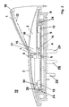
- Fig. 1 shows a button arrangement 26 with three electrical push buttons 10, wherein their respective actuation rockers 3 are essentially visible from the buttons 10 are.
- the rockers 3 are in a base 8 by locking means 24, 25 and spring means 13 held in a rest position.
- the base 8 is more common Base for all buttons 10 of the arrangement 26.
- Each button 10 has a text field 11 and a status display 19.
- With reference numeral 27 is an infrared transparent front cover of the base 8 referred to, but related is not important with the invention. A protrudes through the cover 27 Operating button 20 of a pressure sequence switch or pushbutton, with which the lighting means, let the LEDs 4 switch.
- the title blocks 11 are each through an incision or shaft 21 of the rockers 3 formed, which can be covered by a transparent cover 1.
- the strip-shaped covers 1 are each at their ends with locking elements 17, 18 provided.
- a light guide wedge 2 can be inserted in each of the incisions 21.
- Fig. 1 are different assembly steps for completing the lighting device shown.
- a light guide wedge 2 inserted in the middle button 10 with its first locking element 17 hooked into the rocker 3.
- a transparent label Insert 12 e.g. a translucent film is shown, which is arranged under the cover 1 is.
- the cover 1 is indicated by folding it down Arrow direction closed, being at its second end by means of the second Snap element 18 snaps into rocker 3.
- the covers 1 can be used as a magnifying glass be designed to improve the legibility of one located on the insert 12 Font.
- reference numerals 22, 23 are reflective coatings of the light guide wedge 2 referred to, applied with the recess of the light entry and exit surfaces 14, 16 can be. By such a measure, the brightness on the Increase light exit surface 16.
- Fig. 2 shows a section through the key switch 10 at a point where the Labeling field 11 of the rocker 3 is located.
- the base 8 and the rocker 3 are plastic parts.
- the rocker 3 is with the help of Locking means 24, 25 hooked into the base and is spring-loaded in two Contact elements 13, in particular microswitches, is generated in the rest position held.
- a printed circuit board 9 is arranged in the base 8, on which the contact elements 13, as well as the first LED 4 for lettering field lighting and a second LED 5 for Status display, that is, arranged to display a switching state.
- the contact elements 13 are actuated via actuation cams 30 on the rocker 3.
- the first LED 4 feeds light into the light entry surface 14 of the light guide wedge 2, that emerges at the exit surface 16 and backlit the transparent insert 12.
- the second LED 5 feeds light into a light guide element 6, which is on the surface the rocker 3 emerges as a status display 19.
- a separator 7 at the bottom of the Rocker 3 prevents the passage of light from the lettering field lighting to the status display. It can be seen that the light guides 2, 6 are spaced somewhat apart from the LEDs 4, 5 are, which enables a rocker movement.
- pin 28 and a multiple plug 29 is the key switch 10, or the button arrangement 26 (Fig. 1) attachable to a flush-mounted device, not shown.
Abstract
Description
Die Erfindung bezieht sich auf einen elektrischen Tastschalter mit einer Betätigungswippe, die ein Schriftfeld aufweist. Der Tastschalter kann Teil einer Tasteranordnung mit mehreren solcher Tastschalter sein.The invention relates to an electrical push button switch with an operating rocker, which has a title block. The key switch can be part of a key arrangement be with several such push buttons.
Tasteranordnungen mit beschriftbaren, streifenförmigen Bedienflächen werden vorzugsweise so z.B. an einer Wand montiert, daß die Schriftzeilen horizontal verlaufen, wobei die Betätigungswippe um eine vertikale Achse schwenkt. Es sind Anordnungen bekannt, bei denen ein Rahmen, der mehrere Taster umgibt, ein Schriftfeld trägt, oder bei denen die Tasterwippen ganzflächig oder auf Teilflächen Schriftfelder haben. Solche Tasteranordnungen werden insbesondere zur Bedienung elektronischer Installationsgeräte verwendet. Tasteranordnungen mit beschriftbaren Wippen sind beispielsweise aus G 93 05 822 und G 94 06 434 bekannt.Button arrangements with inscribable, strip-shaped control surfaces are preferred so e.g. mounted on a wall so that the characters run horizontally, the actuating rocker pivots about a vertical axis. They are orders known, in which a frame that surrounds several buttons, a title block bears, or where the pushbuttons cover the entire surface or partial areas of text fields to have. Such button arrangements are particularly electronic to operate Installation devices used. Button arrangements with inscribable rockers are known for example from G 93 05 822 and G 94 06 434.
Nachteilig ist bei den bekannten Tastern, daß eine Beschriftung nur bei vorhandenem Umgebungslicht lesbar ist, da keine Eigenbeleuchtung vorhanden ist.A disadvantage of the known buttons that labeling is only available Ambient light is legible because there is no self-illumination.
Der Erfindung liegt die Aufgabe zugrunde, einen elektrischen Tastschalter anzugeben, dessen Betätigungswippe mit einem beleuchtbaren Schriftfeld versehen ist und wobei eine weitgehend gleichmäßige Hinterleuchtung des Schriftfelds gegeben ist.The invention has for its object to provide an electrical push button switch, the rocker is provided with an illuminated text field and with a largely uniform backlighting of the text field.
Diese Aufgabe wird durch einen Tastschalter mit den im Anspruch 1 angegebenen
Merkmalen gelöst. This object is achieved by a push button switch with the specified in
Bei diesem Taster wird mittels eines Lichtleiterkeils erreicht, daß trotz nahezu punktförmiger Lichteinleitung durch eine lichtemittierende Diode LED eine weitgehend gleichmäßige Hinterleuchtung des gesamten Schriftfelds gegeben ist.This button is achieved by means of a fiber optic wedge, that despite almost punctiform light introduction by a light-emitting diode LED a largely uniform backlighting of the entire text field is given.
Als vorteilhafte Ausgestaltung wird vorgeschlagen, zusätzlich eine Statusanzeige mittels einer weiteren lichtemittierenden Diode LED zu schaffen, deren Licht mittels eines Lichtleiterelements zur Wippenoberfläche geführt wird, und außerdem einen Trennsteg an der Wippenunterseite vorzusehen, mit dem eine gegenseitige Beeinflussung der Beleuchtungseinrichtungen vermieden wird.A status display is also proposed as an advantageous embodiment to create by means of a further light-emitting diode LED, the light of which means a light guide element is guided to the rocker surface, and also one Separator to be provided on the underside of the rocker, with which a mutual influence the lighting equipment is avoided.
Weitere Einzelheiten und Vorteile des Tasters ergeben sich aus der nachstehenden Beschreibung eines Ausführungsbeispiels anhand der Zeichnungsfiguren.Further details and advantages of the button result from the following Description of an embodiment with reference to the drawing figures.
Es zeigen:
- Fig. 1
- eine Tasteranordnung mit drei Tastern, die jeweils ein beleuchtetes Schriftfeld haben und
- Fig. 2
- einen Schnitt durch einen Taster mit Beleuchtungseinrichtungen zur Schriftfeldbeleuchtung und zur Statusanzeige.
- Fig. 1
- a button arrangement with three buttons, each with an illuminated text field and
- Fig. 2
- a section through a button with lighting devices for lettering field lighting and status display.
Fig. 1 zeigt eine Tasteranordnung 26 mit drei elektrischen Tastschaltern 10, wobei
von den Tastern 10 im wesentlichen ihre jeweiligen Betätigungswippen 3 sichtbar
sind. Die Wippen 3 sind in einem Sockel 8 durch Rastmittel 24, 25 und Federmittel
13 in einer Ruhestellung gehalten. Im Ausführungsbeispiel ist der Sockel 8 gemeinsamer
Sockel für alle Taster 10 der Anordnung 26. Jeder Taster 10 hat ein Schriftfeld
11 und eine Statusanzeige 19. Mit Bezugszeichen 27 ist eine infrarotlichtdurchlässige
frontseitige Abdeckung des Sockels 8 bezeichnet, die jedoch im Zusammenhang
mit der Erfindung nicht von Bedeutung ist. Durch die Abdeckung 27 ragt ein
Betätigungsknopf 20 eines Druckfolgeschalters oder Tasters, mit dem sich die Beleuchtungsmittel,
also die LED's 4 schalten lassen.Fig. 1 shows a
Die Schriftfelder 11 sind jeweils durch einen Einschnitt oder Schacht 21 der Wippen
3 gebildet, der jeweils durch eine transparente Abdeckung 1 abdeckbar ist. Die
streifenförmigen Abdeckungen 1 sind jeweils an ihren Enden mit Rastelementen 17,
18 versehen. In die Einschnitte 21 ist jeweils ein Lichtleiterkeil 2 einlegbar.The
In Fig. 1 sind unterschiedliche Montageschritte zur Fertigstellung der Beleuchtungseinrichtung
gezeigt. In den mittleren der drei Taster 10 ist ein Lichtleiterkeil 2
eingelegt. Die Abdeckung 1 ist beim mittleren Taster 10 mit ihrem ersten Rastelement
17 in die Wippe 3 eingehängt. Außerdem ist eine beschriftbare transparente
Einlage 12, z.B. eine transluzente Folie dargestellt, die unter der Abdeckung 1 angeordnet
ist. Die Abdeckung 1 wird durch Herunterklappen in der angegebenen
Pfeilrichtung geschlossen, wobei sie an ihrem zweiten Ende mittels des zweiten
Rastelements 18 in der Wippe 3 einrastet. Die Abdeckungen 1 können als Lupe
ausgebildet sein zur Verbeserung der Lesbarkeit einer auf der Einlage 12 befindlichen
Schrift.In Fig. 1 are different assembly steps for completing the lighting device
shown. In the middle of the three
Mit Bezugszeichen 22, 23 sind reflektierende Beschichtungen des Lichtleiterkeils 2
bezeichnet, die unter Aussparung der Lichtein- und -austrittsflächen 14, 16 aufgebracht
werden können. Durch eine solche Maßnahme läßt sich die Helligkeit an der
Lichtaustrittsfläche 16 erhöhen.With
Fig. 2 zeigt einen Schnitt durch den Tastschalter 10 an einer Stelle, an der sich das
Beschriftungsfeld 11 der Wippe 3 befindet.Fig. 2 shows a section through the
Der Sockel 8 und die Wippe 3 sind Kunststoffteile. Die Wippe 3 ist mit Hilfe von
Rastmitteln 24, 25 in den Sockel eingehängt und wird durch Federkraft, die in zwei
Kontaktelementen 13, insbesondere Mikroschaltern erzeugt wird, in der Ruhelage
gehalten. Im Sockel 8 ist eine Leiterplatte 9 angeordnet, auf der die Kontaktelemente
13, sowie die erste LED 4 zur Schriftfeldbeleuchtung und eine zweite LED 5 zur
Statusanzeige, also zur Anzeige eines Schaltzustands angeordnet sind. Die Kontaktelemente
13 werden über Betätigungsnocken 30 an der Wippe 3 betätigt.The
Die erste LED 4 speist Licht in die Lichteintrittsfläche 14 des Lichtleiterkeils 2 ein,
das an der Austrittsfläche 16 austritt und die transparente Einlage 12 hinterleuchtet.
Die zweite LED 5 speist Licht in ein Lichtleiterelement 6 ein, das an der Oberfläche
der Wippe 3 als Statusanzeige 19 austritt. Ein Trennsteg 7 an der Unterseite der
Wippe 3 verhindert einen Lichtübertritt von der Schriftfeldbeleuchtung zur Statusanzeige.
Es ist ersichtlich, daß die Lichtleiter 2, 6 von den LED's 4, 5 jeweils etwas beabstandet
sind, wodurch eine Wippenbewegung ermöglicht ist.The first LED 4 feeds light into the
Mit Zapfen 28 und einem Mehrfachstecker 29 ist der Tastschalter 10, bzw. Die Tasteranordnung
26 (Fig. 1) auf ein nicht dargestelltes Unterputzgerät aufsteckbar. With
- 11
- transparente Abdeckungtransparent cover
- 22nd
- LichtleiterkeilFiber optic wedge
- 33rd
- BetätigungswippeRocker switch
- 44th
- erste lichtemittierende Diode LEDfirst light-emitting diode LED
- 55
- zweite LEDsecond LED
- 66
- LichtleitelementLight guiding element
- 77
- Trennsteg oder TrennwandDivider or partition
- 88th
- Sockelbase
- 99
- LeiterplatteCircuit board
- 1010th
- TastschalterPush button
- 1111
- SchriftfeldTitle block
- 1212th
- beschriftbare transparente Einlagewritable transparent insert
- 1313
- MikroschalterMicroswitch
- 1414
- LichteintrittsflächeLight entry surface
- 1515
- dickes Keilendethick wedge end
- 1616
- LichtaustrittsflächeLight exit surface
- 1717th
- erstes Rastelement der Abdeckungfirst locking element of the cover
- 1818th
- zweites Rastelement der Abdeckungsecond locking element of the cover
- 1919th
- StatusanzeigeStatus display
- 2020th
- Betätigungsknopf eines Mikroschalters oder TastersActuation button of a microswitch or push button
- 2121
- Lichtleiterschacht oder Einschnitt in der WippeOptical fiber shaft or incision in the seesaw
- 2222
- erste Beschichtungfirst coating
- 2323
- zweite Beschichtungsecond coating
- 2424th
- Rasthaken oder Rastmittel der WippeLocking hook or locking means of the rocker
- 2525th
- Rastmittel am SockelLatching means on the base
- 2626
- TastschalteranordnungPush button arrangement
- 2727
- infrarotlichtdurchlässige AbdeckungInfrared transparent cover
- 2828
- ZapfenCones
- 2929
- MehrfachsteckerMultiple plug
- 3030th
- BetätigungsnockenActuating cams
Claims (9)
Applications Claiming Priority (2)
| Application Number | Priority Date | Filing Date | Title |
|---|---|---|---|
| DE19737908A DE19737908A1 (en) | 1997-09-01 | 1997-09-01 | Electric key switch with text field |
| DE19737908 | 1997-09-01 |
Publications (3)
| Publication Number | Publication Date |
|---|---|
| EP0899760A2 true EP0899760A2 (en) | 1999-03-03 |
| EP0899760A3 EP0899760A3 (en) | 1999-09-15 |
| EP0899760B1 EP0899760B1 (en) | 2003-08-27 |
Family
ID=7840689
Family Applications (1)
| Application Number | Title | Priority Date | Filing Date |
|---|---|---|---|
| EP98111591A Expired - Lifetime EP0899760B1 (en) | 1997-09-01 | 1998-06-24 | Electrical push-button switch with legend |
Country Status (3)
| Country | Link |
|---|---|
| EP (1) | EP0899760B1 (en) |
| AT (1) | ATE248430T1 (en) |
| DE (2) | DE19737908A1 (en) |
Cited By (7)
| Publication number | Priority date | Publication date | Assignee | Title |
|---|---|---|---|---|
| DE10242171C1 (en) * | 2002-09-10 | 2003-08-21 | Abb Patent Gmbh | Rocker for an electrical unit, has a large surface light conductor to give a homogenous illumination over visible field, placed centrally at rocker surface area together with injection molded function elements |
| EP1385185A2 (en) * | 2002-07-26 | 2004-01-28 | ABB PATENT GmbH | Label field illumination for an electrical installation device |
| DE10246399B3 (en) * | 2002-10-04 | 2004-02-19 | Abb Patent Gmbh | Writing field illumination for electrical installation device e.g. wall-mounted switch, uses electroluminescent foil positioned in writing field chamber below printed foil |
| DE10242170B4 (en) * | 2002-09-10 | 2005-07-21 | Abb Patent Gmbh | Optical fiber of an electrical installation device |
| DE202004018756U1 (en) * | 2004-12-04 | 2006-04-13 | Weidmüller Interface GmbH & Co. KG | Electrical device with a status indicator |
| EP2509086A1 (en) * | 2011-04-06 | 2012-10-10 | Abb Ag | Rocker holder with at least one actuation rocker of a door station or residence station of a building communication system |
| EP2509087A1 (en) * | 2011-04-06 | 2012-10-10 | Abb Ag | Rocker holder with at least one actuation rocker of a door station or residence station of a building communication system |
Families Citing this family (3)
| Publication number | Priority date | Publication date | Assignee | Title |
|---|---|---|---|---|
| DE20222010U1 (en) * | 2002-09-30 | 2010-09-23 | BSH Bosch und Siemens Hausgeräte GmbH | switch device |
| DE10325344A1 (en) * | 2003-06-05 | 2004-12-30 | Daimlerchrysler Ag | Electrical switch has built in lighting provided by a strip of light emitting diode elements with a diffuser plate |
| DE102013205577A1 (en) * | 2013-03-28 | 2014-10-02 | Zf Friedrichshafen Ag | Key module for a key of a keyboard and method for producing a key module for a key of a keyboard |
Citations (5)
| Publication number | Priority date | Publication date | Assignee | Title |
|---|---|---|---|---|
| DE3314323A1 (en) * | 1983-04-20 | 1984-10-31 | Robert Bosch Gmbh, 7000 Stuttgart | Device for illuminating passive displays |
| DE9015937U1 (en) * | 1990-11-22 | 1991-02-07 | Erwin Renz Metallwarenfabrik Gmbh + Co Kg, 7141 Kirchberg, De | |
| US5063379A (en) * | 1986-11-14 | 1991-11-05 | Robert Bosch Gmbh | Liquid crystal indicator, preferably for motor vehicles |
| DE9305822U1 (en) * | 1993-04-20 | 1993-06-24 | Gira Giersiepen Gmbh & Co Kg, 5608 Radevormwald, De | |
| DE9406434U1 (en) * | 1994-04-18 | 1994-09-08 | Giersiepen Gira Gmbh | Electrical push button |
Family Cites Families (1)
| Publication number | Priority date | Publication date | Assignee | Title |
|---|---|---|---|---|
| JPS61127506U (en) * | 1985-01-30 | 1986-08-11 |
-
1997
- 1997-09-01 DE DE19737908A patent/DE19737908A1/en not_active Withdrawn
-
1998
- 1998-06-24 AT AT98111591T patent/ATE248430T1/en active
- 1998-06-24 EP EP98111591A patent/EP0899760B1/en not_active Expired - Lifetime
- 1998-06-24 DE DE59809396T patent/DE59809396D1/en not_active Expired - Lifetime
Patent Citations (5)
| Publication number | Priority date | Publication date | Assignee | Title |
|---|---|---|---|---|
| DE3314323A1 (en) * | 1983-04-20 | 1984-10-31 | Robert Bosch Gmbh, 7000 Stuttgart | Device for illuminating passive displays |
| US5063379A (en) * | 1986-11-14 | 1991-11-05 | Robert Bosch Gmbh | Liquid crystal indicator, preferably for motor vehicles |
| DE9015937U1 (en) * | 1990-11-22 | 1991-02-07 | Erwin Renz Metallwarenfabrik Gmbh + Co Kg, 7141 Kirchberg, De | |
| DE9305822U1 (en) * | 1993-04-20 | 1993-06-24 | Gira Giersiepen Gmbh & Co Kg, 5608 Radevormwald, De | |
| DE9406434U1 (en) * | 1994-04-18 | 1994-09-08 | Giersiepen Gira Gmbh | Electrical push button |
Cited By (16)
| Publication number | Priority date | Publication date | Assignee | Title |
|---|---|---|---|---|
| EP1385185A2 (en) * | 2002-07-26 | 2004-01-28 | ABB PATENT GmbH | Label field illumination for an electrical installation device |
| DE10234023A1 (en) * | 2002-07-26 | 2004-02-05 | Abb Patent Gmbh | Labeling field lighting of an electrical installation device |
| EP1385185A3 (en) * | 2002-07-26 | 2005-04-20 | ABB PATENT GmbH | Label field illumination for an electrical installation device |
| DE10234023B4 (en) * | 2002-07-26 | 2010-02-11 | Abb Ag | Labeling field illumination of an electrical installation device |
| DE10242171C1 (en) * | 2002-09-10 | 2003-08-21 | Abb Patent Gmbh | Rocker for an electrical unit, has a large surface light conductor to give a homogenous illumination over visible field, placed centrally at rocker surface area together with injection molded function elements |
| DE10242170B4 (en) * | 2002-09-10 | 2005-07-21 | Abb Patent Gmbh | Optical fiber of an electrical installation device |
| DE10246399B3 (en) * | 2002-10-04 | 2004-02-19 | Abb Patent Gmbh | Writing field illumination for electrical installation device e.g. wall-mounted switch, uses electroluminescent foil positioned in writing field chamber below printed foil |
| DE202004018756U1 (en) * | 2004-12-04 | 2006-04-13 | Weidmüller Interface GmbH & Co. KG | Electrical device with a status indicator |
| EP2509086A1 (en) * | 2011-04-06 | 2012-10-10 | Abb Ag | Rocker holder with at least one actuation rocker of a door station or residence station of a building communication system |
| EP2509087A1 (en) * | 2011-04-06 | 2012-10-10 | Abb Ag | Rocker holder with at least one actuation rocker of a door station or residence station of a building communication system |
| CN102737888A (en) * | 2011-04-06 | 2012-10-17 | Abb股份有限公司 | Rocker holder with at least one actuation rocker of a door station or residence station of a building communication system |
| CN102737889A (en) * | 2011-04-06 | 2012-10-17 | Abb股份有限公司 | Rocker holder with at least one actuation rocker of a door station or residence station of a building communication system |
| CN102737888B (en) * | 2011-04-06 | 2016-03-09 | Abb股份有限公司 | There is the rocker holder of the manipulation seesaw of door switch or room switch |
| RU2583152C2 (en) * | 2011-04-06 | 2016-05-10 | Абб Аг | Holder of throw-over button with at least one control button throw-over door station or apartment station for home communication system |
| RU2598534C2 (en) * | 2011-04-06 | 2016-09-27 | Абб Аг | Rocker switch with at least one swing button for controlling the door or apartment device of the home communication system |
| CN102737889B (en) * | 2011-04-06 | 2016-12-14 | Abb股份有限公司 | There is the door trip of at least one house communication system or the rocker holder handling seesaw of room switch |
Also Published As
| Publication number | Publication date |
|---|---|
| ATE248430T1 (en) | 2003-09-15 |
| EP0899760A3 (en) | 1999-09-15 |
| DE19737908A1 (en) | 1999-03-04 |
| DE59809396D1 (en) | 2003-10-02 |
| EP0899760B1 (en) | 2003-08-27 |
Similar Documents
| Publication | Publication Date | Title |
|---|---|---|
| EP1166013B1 (en) | Front-illuminated Display Device | |
| DE102007014264B4 (en) | Illuminated switch position indicator | |
| DE3033096A1 (en) | DEVICE FOR UNIFORM ILLUMINATION OF WRITING FIELDS | |
| EP1257057A1 (en) | Sensor element for a capacitive touch switch | |
| DE3535217C2 (en) | ||
| DE2705394C2 (en) | Device for the visual display of the keys for a keyboard instrument assigned to the notes of a chord to be played | |
| EP0899760B1 (en) | Electrical push-button switch with legend | |
| EP1385188B1 (en) | Electrical switchgear | |
| EP1873596B1 (en) | Portable radio remote control transmitter with backlit pushbuttons | |
| DE19737907B4 (en) | keyswitch | |
| DE8032982U1 (en) | Device for illuminating the keys of a keypad | |
| DE3628781A1 (en) | Film keyboard | |
| DE10011800B4 (en) | lighting device | |
| DE3511026C2 (en) | ||
| DE3524492A1 (en) | Opto-electrical device with a multiplicity of operating elements in a panel | |
| EP0022516B1 (en) | Signalling element without lamp | |
| DE4414981A1 (en) | Electrical control module with light guide for receiving at least one incandescent lamp | |
| DE10044077B4 (en) | Push button arrangement | |
| EP0580082B1 (en) | Optoelectronic device | |
| EP2513872B1 (en) | Tachograph | |
| WO2002074041A2 (en) | Display device | |
| DE19918055A1 (en) | Mobile communications terminal | |
| DE10142581A1 (en) | Computer keyboard has illuminable key-pad or illumination effect | |
| WO2005029819A1 (en) | Door station comprising nameplates and doorbell buttons | |
| DE102009057187A1 (en) | Illuminable element i.e. actuating member, for illuminating electrical switch, has light conductor made of flexible foil and designed as foil light conductor, where light is guided by total reflection within foil light conductor |
Legal Events
| Date | Code | Title | Description |
|---|---|---|---|
| PUAI | Public reference made under article 153(3) epc to a published international application that has entered the european phase |
Free format text: ORIGINAL CODE: 0009012 |
|
| AK | Designated contracting states |
Kind code of ref document: A2 Designated state(s): AT BE CH DE DK FI LI NL SE |
|
| AX | Request for extension of the european patent |
Free format text: AL;LT;LV;MK;RO;SI |
|
| PUAL | Search report despatched |
Free format text: ORIGINAL CODE: 0009013 |
|
| AK | Designated contracting states |
Kind code of ref document: A3 Designated state(s): AT BE CH CY DE DK ES FI FR GB GR IE IT LI LU MC NL PT SE |
|
| AX | Request for extension of the european patent |
Free format text: AL;LT;LV;MK;RO;SI |
|
| 17P | Request for examination filed |
Effective date: 20000121 |
|
| EUG | Se: european patent has lapsed | ||
| AKX | Designation fees paid |
Free format text: AT BE CH DE DK FI LI NL SE |
|
| RAP1 | Party data changed (applicant data changed or rights of an application transferred) |
Owner name: ABB PATENT GMBH |
|
| GRAH | Despatch of communication of intention to grant a patent |
Free format text: ORIGINAL CODE: EPIDOS IGRA |
|
| GRAH | Despatch of communication of intention to grant a patent |
Free format text: ORIGINAL CODE: EPIDOS IGRA |
|
| GRAA | (expected) grant |
Free format text: ORIGINAL CODE: 0009210 |
|
| AK | Designated contracting states |
Designated state(s): AT BE CH DE DK FI LI NL SE |
|
| REG | Reference to a national code |
Ref country code: CH Ref legal event code: EP |
|
| REF | Corresponds to: |
Ref document number: 59809396 Country of ref document: DE Date of ref document: 20031002 Kind code of ref document: P |
|
| REG | Reference to a national code |
Ref country code: SE Ref legal event code: TRGR |
|
| PG25 | Lapsed in a contracting state [announced via postgrant information from national office to epo] |
Ref country code: DK Free format text: LAPSE BECAUSE OF FAILURE TO SUBMIT A TRANSLATION OF THE DESCRIPTION OR TO PAY THE FEE WITHIN THE PRESCRIBED TIME-LIMIT Effective date: 20031127 |
|
| PLBE | No opposition filed within time limit |
Free format text: ORIGINAL CODE: 0009261 |
|
| STAA | Information on the status of an ep patent application or granted ep patent |
Free format text: STATUS: NO OPPOSITION FILED WITHIN TIME LIMIT |
|
| 26N | No opposition filed |
Effective date: 20040528 |
|
| PGFP | Annual fee paid to national office [announced via postgrant information from national office to epo] |
Ref country code: NL Payment date: 20050615 Year of fee payment: 8 |
|
| PGFP | Annual fee paid to national office [announced via postgrant information from national office to epo] |
Ref country code: SE Payment date: 20060614 Year of fee payment: 9 |
|
| PGFP | Annual fee paid to national office [announced via postgrant information from national office to epo] |
Ref country code: BE Payment date: 20060712 Year of fee payment: 9 |
|
| PG25 | Lapsed in a contracting state [announced via postgrant information from national office to epo] |
Ref country code: NL Free format text: LAPSE BECAUSE OF NON-PAYMENT OF DUE FEES Effective date: 20070101 |
|
| NLV4 | Nl: lapsed or anulled due to non-payment of the annual fee |
Effective date: 20070101 |
|
| BERE | Be: lapsed |
Owner name: *ABB PATENT G.M.B.H. Effective date: 20070630 |
|
| EUG | Se: european patent has lapsed | ||
| PG25 | Lapsed in a contracting state [announced via postgrant information from national office to epo] |
Ref country code: BE Free format text: LAPSE BECAUSE OF NON-PAYMENT OF DUE FEES Effective date: 20070630 |
|
| PG25 | Lapsed in a contracting state [announced via postgrant information from national office to epo] |
Ref country code: SE Free format text: LAPSE BECAUSE OF NON-PAYMENT OF DUE FEES Effective date: 20070625 |
|
| PGFP | Annual fee paid to national office [announced via postgrant information from national office to epo] |
Ref country code: FI Payment date: 20080613 Year of fee payment: 11 |
|
| PG25 | Lapsed in a contracting state [announced via postgrant information from national office to epo] |
Ref country code: FI Free format text: LAPSE BECAUSE OF NON-PAYMENT OF DUE FEES Effective date: 20090624 |
|
| PGFP | Annual fee paid to national office [announced via postgrant information from national office to epo] |
Ref country code: CH Payment date: 20160620 Year of fee payment: 19 |
|
| PGFP | Annual fee paid to national office [announced via postgrant information from national office to epo] |
Ref country code: AT Payment date: 20160621 Year of fee payment: 19 |
|
| PGFP | Annual fee paid to national office [announced via postgrant information from national office to epo] |
Ref country code: DE Payment date: 20170621 Year of fee payment: 20 |
|
| REG | Reference to a national code |
Ref country code: CH Ref legal event code: PL |
|
| REG | Reference to a national code |
Ref country code: AT Ref legal event code: MM01 Ref document number: 248430 Country of ref document: AT Kind code of ref document: T Effective date: 20170624 |
|
| PG25 | Lapsed in a contracting state [announced via postgrant information from national office to epo] |
Ref country code: CH Free format text: LAPSE BECAUSE OF NON-PAYMENT OF DUE FEES Effective date: 20170630 Ref country code: LI Free format text: LAPSE BECAUSE OF NON-PAYMENT OF DUE FEES Effective date: 20170630 |
|
| PG25 | Lapsed in a contracting state [announced via postgrant information from national office to epo] |
Ref country code: AT Free format text: LAPSE BECAUSE OF NON-PAYMENT OF DUE FEES Effective date: 20170624 |
|
| REG | Reference to a national code |
Ref country code: DE Ref legal event code: R071 Ref document number: 59809396 Country of ref document: DE |