EP0899487B1 - Internal control device for a gearbox with system for maintaining control elements in several positions - Google Patents
Internal control device for a gearbox with system for maintaining control elements in several positions Download PDFInfo
- Publication number
- EP0899487B1 EP0899487B1 EP19980402001 EP98402001A EP0899487B1 EP 0899487 B1 EP0899487 B1 EP 0899487B1 EP 19980402001 EP19980402001 EP 19980402001 EP 98402001 A EP98402001 A EP 98402001A EP 0899487 B1 EP0899487 B1 EP 0899487B1
- Authority
- EP
- European Patent Office
- Prior art keywords
- finger
- shaft
- control
- balls
- gearbox
- Prior art date
- Legal status (The legal status is an assumption and is not a legal conclusion. Google has not performed a legal analysis and makes no representation as to the accuracy of the status listed.)
- Expired - Lifetime
Links
Images
Classifications
-
- F—MECHANICAL ENGINEERING; LIGHTING; HEATING; WEAPONS; BLASTING
- F16—ENGINEERING ELEMENTS AND UNITS; GENERAL MEASURES FOR PRODUCING AND MAINTAINING EFFECTIVE FUNCTIONING OF MACHINES OR INSTALLATIONS; THERMAL INSULATION IN GENERAL
- F16H—GEARING
- F16H63/00—Control outputs from the control unit to change-speed- or reversing-gearings for conveying rotary motion or to other devices than the final output mechanism
- F16H63/02—Final output mechanisms therefor; Actuating means for the final output mechanisms
- F16H63/30—Constructional features of the final output mechanisms
- F16H63/34—Locking or disabling mechanisms
- F16H63/36—Interlocking devices
-
- F—MECHANICAL ENGINEERING; LIGHTING; HEATING; WEAPONS; BLASTING
- F16—ENGINEERING ELEMENTS AND UNITS; GENERAL MEASURES FOR PRODUCING AND MAINTAINING EFFECTIVE FUNCTIONING OF MACHINES OR INSTALLATIONS; THERMAL INSULATION IN GENERAL
- F16H—GEARING
- F16H63/00—Control outputs from the control unit to change-speed- or reversing-gearings for conveying rotary motion or to other devices than the final output mechanism
- F16H63/02—Final output mechanisms therefor; Actuating means for the final output mechanisms
- F16H63/30—Constructional features of the final output mechanisms
- F16H63/34—Locking or disabling mechanisms
- F16H63/3408—Locking or disabling mechanisms the locking mechanism being moved by the final actuating mechanism
-
- F—MECHANICAL ENGINEERING; LIGHTING; HEATING; WEAPONS; BLASTING
- F16—ENGINEERING ELEMENTS AND UNITS; GENERAL MEASURES FOR PRODUCING AND MAINTAINING EFFECTIVE FUNCTIONING OF MACHINES OR INSTALLATIONS; THERMAL INSULATION IN GENERAL
- F16H—GEARING
- F16H63/00—Control outputs from the control unit to change-speed- or reversing-gearings for conveying rotary motion or to other devices than the final output mechanism
- F16H63/02—Final output mechanisms therefor; Actuating means for the final output mechanisms
- F16H63/30—Constructional features of the final output mechanisms
- F16H63/38—Detents
Definitions
- a control axis carries at least one finger transverse and a part called an interlocking key, the finger being fixed at the axis and suitable for being selectively engaged first, by sliding of the axis, in one of several notches each arranged in one of said elements, then to drive by rotation of the axis the element as well selected, in order to achieve the commitment -or transition- from a ratio, while the interlocking key is axially integral with the axis, stationary in rotation and suitable for being engaged, by sliding of the axis, in the notches other than that of the selected element, of so as to immobilize the other elements of engagement.
- These commands include means for maintaining the the above elements in several corresponding positions of use respectively in the neutral position of the gearbox and in the engagement of either of several reports.
- US Patent 4,539,859 thus describes a internal manual gearbox control in which the control axis carries a finger transverse including ramps at one of its ends and an interlocking key including two identical radial arms between which the other end of the finger is movable and, in which the support billing is mounted in a housing reported by screwing on the gearbox housing so that the ball comes to rest against the finger ramps.
- the proposed command is of the aforementioned type, with a ball or roller holding device carried by the finger and pushed parallel to the axis against a ramp carried by the key interlocking;
- this key comprises two radial arms between which the finger is movable in rotation, and the holding device has two balls or rollers carried by the finger and pushed in opposite directions respectively against two opposite ramps carried each by one of the two arms.
- a finger 5 secured to a hub 6 fixed to the axis 2 by a pin 7 extends radially so that its free end 8 is located at the level of notches 9 practiced respectively in several elements 10,11,12 movable orthogonally to axis 2.
- finger 5 and arms 17 and 18 of the key 16 are arranged relative to the movable elements 10, 11, 12 so known such that, by sliding the axis 2, the finger 5 is able to be first selectively engaged in one of the notches 9 then to train the element (for example 11) thus selected, by rotation of axis 2, of so as to carry out the passage of one of two corresponding reports, while the interlocking key 16 immobilizes the other elements (for example 10 and 12) by engagement of the end of at least one of its arms 17 and 18 in the notches of these other elements.
- finger 5 is fixed, for example by welding, a tubular piece or socket 22, so that it is parallel to axis 2; this socket coaxially contains a helical spring 23 and, on either side thereof, two balls 24 which protrude slightly and respectively from the two ends of the socket in being pushed in opposite directions by the spring 23, with interposition of support pads 25, each against one of two ramps 26,27 opposite secured respectively to the two arms 17 and 18 of the key.
- These ramps preferably made of very hard material and attached to the arms 17 and 18 by any non-fixing means shown, each have three notches 28 in which can alternately engage the associated ball, causing immobilization temporary -or holding- finger 5 between the two arms 17 and 18. These notches are arranged so that the positions of the finger thus maintained that they determine correspond respectively to neutral for the central notch and to the two reporting commitments ensured by the element mobile 10,11 or 12 selected.
Description
L'invention est relative à une commande interne de boíte de vitesses avec dispositif de maintien d'éléments en plusieurs positions.The invention relates to an internal gearbox control with device for holding elements in several positions.
Elle concerne plus précisément les commandes de vitesses dans lesquelles, pour déplacer alternativement plusieurs éléments juxtaposés d'engagement de rapports, un axe de commande porte au moins un doigt transversal et une pièce dite clé d'interverrouillage, le doigt étant fixé à l'axe et propre à être d'abord engagé sélectivement, par coulissement de l'axe, dans l'une de plusieurs encoches agencées chacune dans l'un desdits éléments, puis à entraíner par rotation de l'axe l'élément ainsi sélectionné, de manière à réaliser l'engagement -ou passage- d'un rapport, tandis que la clé d'interverrouillage est solidaire axialement de l'axe, immobile en rotation et propre à être engagée, par coulissement de l'axe, dans les autres encoches que celle de l'élément sélectionné, de manière à immobiliser les autres éléments d'engagement.It relates more specifically to the speed controls in which, to alternately move several juxtaposed elements of engagement of reports, a control axis carries at least one finger transverse and a part called an interlocking key, the finger being fixed at the axis and suitable for being selectively engaged first, by sliding of the axis, in one of several notches each arranged in one of said elements, then to drive by rotation of the axis the element as well selected, in order to achieve the commitment -or transition- from a ratio, while the interlocking key is axially integral with the axis, stationary in rotation and suitable for being engaged, by sliding of the axis, in the notches other than that of the selected element, of so as to immobilize the other elements of engagement.
Ces commandes comprennent des moyens de maintien des susdits éléments en plusieurs positions d'utilisation correspondant respectivement au point mort de la boíte de vitesses et à l'engagement de l'un ou l'autre de plusieurs rapports.These commands include means for maintaining the the above elements in several corresponding positions of use respectively in the neutral position of the gearbox and in the engagement of either of several reports.
Ces moyens, généralement constitués d'une bille ou d'une roulette poussée par un ressort contre une face dite rampe munie de crans appropriés, sont de préférence disposés, dans la tringlerie de commande reliant les susdits éléments à un levier de manoeuvre extérieur, au niveau du doigt donc plutôt "en amont" dans la commande interne, ce qui évite que d'éventuels jeux de fonctionnement entre le doigt et lesdits éléments, et entre ceux-ci et d'autres organes de la commande situés "en aval", soient ressentis désagréablement par l'utilisateur au niveau du levier de manoeuvre.These means, generally consisting of a ball or a roulette pushed by a spring against a face called ramp provided with notches are preferably arranged in the control linkage connecting the above elements to an external operating lever, at the level therefore rather "upstream" in the internal control, which avoids that possible operating clearances between the finger and said elements, and between these and other control units located "downstream", are unpleasantly felt by the user at the level of the maneuver.
Toutefois les dispositifs connus comprenant de tels moyens de maintien à rampe et ressort, parfois désignés "billages", présentent l'inconvénient que la poussée du ressort provoqué des efforts parasites dans les pièces mobiles avoisinantes, générateurs de frottements et par suite de dureté et d'imprécision dans la commande, ainsi que d'usure de ces pièces. However, the known devices comprising such means of ramp and spring support, sometimes called "billing", have the disadvantage that the spring thrust caused parasitic forces in nearby moving parts, friction generators and by hardness and imprecision in the control, as well as wear and tear these parts.
Le brevet US 4 539 859 décrit ainsi une commande interne de boite de vitesses manuelle dans laquelle l'axe de commande porte un doigt transversal comprenant des rampes à l'une de ses extrémités et une clé d'interverrouillage comprenant deux bras radiaux identiques entre lesquels l'autre extrémité du doigt est mobile et, dans laquelle le billage de maintien est monté dans un logement rapporté par vissage sur le carter de boite de sorte que la bille vienne en appui contre les rampes du doigt. US Patent 4,539,859 thus describes a internal manual gearbox control in which the control axis carries a finger transverse including ramps at one of its ends and an interlocking key including two identical radial arms between which the other end of the finger is movable and, in which the support billing is mounted in a housing reported by screwing on the gearbox housing so that the ball comes to rest against the finger ramps.
L'invention vise à éviter ces inconvénients en proposant une commande interne de boíte de vitesses comportant des moyens de maintien par billage qui soient disposés en amont et qui ne provoquent pas d'efforts parasites générateurs de frottements.The invention aims to avoid these drawbacks by proposing a internal control of gearbox comprising means of holding by billing which are arranged upstream and which do not cause no parasitic forces generating friction.
A cet effet, la commande proposée est du type susmentionné, avec un dispositif de maintien à bille ou roulette portée par le doigt et poussée parallèlement à l'axe contre une rampe portée par la clé d'interverrouillage ; selon l'invention, cette clé comporte deux bras radiaux entre lesquels le doigt est mobile en rotation, et le dispositif de maintien comporte deux billes ou roulettes portées par le doigt et poussées en sens inverses respectivement contre deux rampes en vis-à-vis portées chacune par l'un des deux bras.For this purpose, the proposed command is of the aforementioned type, with a ball or roller holding device carried by the finger and pushed parallel to the axis against a ramp carried by the key interlocking; according to the invention, this key comprises two radial arms between which the finger is movable in rotation, and the holding device has two balls or rollers carried by the finger and pushed in opposite directions respectively against two opposite ramps carried each by one of the two arms.
Selon quelques dispositions intéressantes de l'invention :
- les deux billes ou roulettes sont poussées par un même ressort interposé entre elles ;
- le dispositif de maintien comportant deux billes, celles-ci et le ressort sont logés dans une pièce tubulaire solidaire du doigt ;
- un coussinet d'appui est interposé entre le ressort et chaque bille ;
- les rampes sont formées chacune sur une pièce en matériau dur rapportée sur le bras associé.
- the two balls or rollers are pushed by the same spring interposed between them;
- the holding device comprising two balls, these and the spring are housed in a tubular piece integral with the finger;
- a bearing pad is interposed between the spring and each ball;
- the ramps are each formed on a piece of hard material attached to the associated arm.
Un mode de réalisation d'une commande selon la présente invention est décrit ci-après, avec référence aux dessins annexés parmi lesquels :
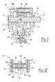
- la figure 1 est une vue en coupe axiale partielle d'une partie de boíte de vitesses comportant le dispositif de maintien de la commande ;
- la figure 2 est une vue à plus grande échelle, en coupe axiale, du dispositif de maintien.
- Figure 1 is a partial axial sectional view of a gearbox part comprising the control holding device;
- Figure 2 is an enlarged view, in axial section, of the holding device.
On voit sur la figure 1, dans un carter 1 d'une boíte de vitesses, un
axe de commande 2 propre à coulisser et à tourner, sous l'action d'un
levier de manoeuvre extérieur non représenté, dans deux paliers 3 et 4
agencés dans des parois parallèles la et 1b du carter.We see in Figure 1, in a
Un doigt 5 solidaire d'un moyeu 6 fixé à l'axe 2 par une goupille 7
s'étend radialement de sorte que son extrémité libre 8 soit située au
niveau d'encoches 9 pratiquées respectivement dans plusieurs éléments
10,11,12 mobiles orthogonalement à l'axe 2.A
Ces éléments 10,11,12 font partie chacun d'une tige coulissante
13,14 ou d'un levier pivotant 15 d'actionnement d'au moins une fourchette
propre à déplacer un pignon ou un crabot pour réaliser l'engagement ou
le dégagement de l'un des rapports de la boíte de vitesses.These
Ils permettent ainsi par exemple de passer respectivement des rapports de 1ère ou 2ème, 3ème ou 4ème, 5ème ou marche arrière selon qu'ils sont déplacés dans un sens ou dans l'autre, perpendiculairement au plan de la figure 1.They allow for example to pass respectively 1st or 2nd, 3rd or 4th, 5th or reverse gear according to that they are moved in one direction or the other, perpendicular to the plan of figure 1.
L'axe de commande 2 porte aussi une clé d'interverrouillage 16
munie de deux bras radiaux 17 et 18 dont l'extrémité libre est située au
niveau des encoches 9. Cette clé 16, traversée de façon libre en rotation
par l'axe 2, est rendue solidaire axialement de celui-ci par chevauchement
du moyeu 6, et elle est immobilisée en rotation par coopération d'une
extension 16a qu'elle comporte avec une tige fixe 19 de guidage de
ressorts 20 et 21 de rappel en position axiale centrale représentée.The
Les extrémités respectives du doigt 5 et des bras 17 et 18 de la clé
16 sont disposées, par rapport aux éléments mobiles 10,11,12 de façon
connue telle que, par coulissement de l'axe 2, le doigt 5 est propre à être
d'abord sélectivement engagé dans l'une des encoches 9 puis à entraíner
l'élément (par exemple 11) ainsi sélectionné, par rotation de l'axe 2, de
manière à réaliser le passage de l'un de deux rapports correspondants,
tandis que la clé d'interverrouillage 16 immobilise les autres éléments
(par exemple 10 et 12) par engagement de l'extrémité d'au moins un de
ses bras 17 et 18 dans les encoches de ces autres éléments.The respective ends of
Selon l'invention, comme visible à la figuré 2, au doigt 5 est fixée,
par exemple par soudage, une pièce tubulaire ou douille 22, de façon
qu'elle soit parallèle à l'axe 2 ; cette douille contient coaxialement un
ressort hélicoïdal 23 et, de part et d'autre de celui-ci, deux billes 24 qui
saillent légèrement et respectivement des deux extrémités de la douille en
étant poussées en sens inverses par le ressort 23, avec interposition de
coussinets d'appui 25, chacune contre l'une de deux rampes 26,27 en vis-à-vis
solidaires respectivement des deux bras 17 et 18 de la clé.According to the invention, as shown in FIG. 2,
Ces rampes, de préférence en matériau de grande dureté et
rapportées sur les bras 17 et 18 par un moyen de fixation quelconque non
représenté, comportent chacune trois crans 28 dans lesquels peut
s'engager alternativement la bille associée, provoquant l'immobilisation
provisoire -ou le maintien- du doigt 5 entre les deux bras 17 et 18. Ces
crans sont disposés de façon que les positions du doigt ainsi maintenu
qu'ils déterminent correspondent respectivement au point mort pour le
cran central et aux deux engagements de rapports assurés par l'élément
mobiles 10,11 ou 12 sélectionné.These ramps, preferably made of very hard material and
attached to the
Ainsi, lors de chaque manoeuvre de passage ou de dégagement
d'un rapport, le doigt 5 pivotant avec l'axe 2 entre les deux bras 17 et 18
immobiles de la clé 16, la douille 22 est déplacée entre les deux rampes
26,27, et les billes 24 roulent sur les rampes d'un cran à un autre en
comprimant le ressort 23. Dès que les billes parviennent au cran
correspondant au rapport ou au point mort choisi par l'utilisateur de la
boíte de vitesses, elles s'y maintiennent grâce à la poussée du ressort 23,
d'où résulte le maintien du doigt 5, donc de l'élément mobile sélectionné,
dans la position choisie.Thus, during each passage or clearance maneuver
of a report, the
Les deux billes, étant poussées en sens inverses, exercent sur les
bras 17 et 18 des efforts opposés qui, s'appliquant en interne sur la clé
16, ne sont pas transmis à l'axe 2 et n'induisent donc aucun frottement au
droit de la portée de la clé 16 sur l'axe 2 et au droit des paliers 3 et 4. Il
en résulte que les manoeuvres s'effectuent avec douceur et précision et
que les usures sont minimales.The two balls, being pushed in opposite directions, exert on the
Diverses variantes peuvent être réalisées sans modifier les
caractéristiques de l'invention : ainsi par exemple deux roulettes d'un type
connu utilisées dans d'autres dispositifs de maintien d'éléments d'une
commande de boíte de vitesses peuvent remplacer les billes 24 pour
coopérer de la même façon avec deux rampes à crans adaptées, celles-ci
étant essentiellement disposées en vis-à-vis sur les deux bras de la clé
de verrouillage.Various variants can be produced without modifying the
characteristics of the invention: thus for example two castors of a type
known used in other devices for holding elements of a
gearbox control can replace the
Claims (5)
- Internal control for a gear box in which, in order to displace alternately several moveable members (10, 11, 12) for putting into gear, a control shaft (2) carries on the one hand a transverse finger (5) fixed to the shaft (2) and suitable for first selecting, by sliding of the control shaft, one of said members (10, 11, 12), then for driving, by rotation of the control shaft, said member thus selected, so as to carryout the engagement or disengagement of gears, and on the other hand an interlocking key (16) integral axially with the shaft (2) and immobile in rotation, whilst a device for holding said moveable members (10, 11, 12) is interposed between the finger (5) and the interlocking key (16), said key (16) has two radial arms (17, 18) between which the finger (5) is moveable in rotation, characterised in that said holding device (M) has two balls (24) or wheels carried by the finger (5) and pushed, parallel to the shaft, in inverse directions respectively against two ramps (26, 27) facing each other, each carried by one of the two arms (17, 18).
- Control according to Claim 1, characterised in that the two balls (24) or wheels are pushed by the same spring (23), interposed between them.
- Control according to Claim 2, characterised in that the two balls (24) and the spring (23) are housed in a tubular part (22) integral with the finger (5).
- Control according to Claim 3, characterised in that a support bushing (25) is interposed between the spring (23) and each ball (24).
- Control according to any one of the preceding claims, characterised in that the ramps (26, 27) are each formed on a part made of hard material added on the associated arm (17, 18).
Applications Claiming Priority (2)
| Application Number | Priority Date | Filing Date | Title |
|---|---|---|---|
| FR9710782A FR2767891B1 (en) | 1997-08-29 | 1997-08-29 | INTERNAL GEARBOX CONTROL WITH DEVICE FOR HOLDING COMPONENTS IN MULTIPLE POSITIONS |
| FR9710782 | 1997-08-29 |
Publications (2)
| Publication Number | Publication Date |
|---|---|
| EP0899487A1 EP0899487A1 (en) | 1999-03-03 |
| EP0899487B1 true EP0899487B1 (en) | 2002-05-29 |
Family
ID=9510587
Family Applications (1)
| Application Number | Title | Priority Date | Filing Date |
|---|---|---|---|
| EP19980402001 Expired - Lifetime EP0899487B1 (en) | 1997-08-29 | 1998-08-06 | Internal control device for a gearbox with system for maintaining control elements in several positions |
Country Status (4)
| Country | Link |
|---|---|
| EP (1) | EP0899487B1 (en) |
| DE (1) | DE69805580T2 (en) |
| ES (1) | ES2176933T3 (en) |
| FR (1) | FR2767891B1 (en) |
Families Citing this family (4)
| Publication number | Priority date | Publication date | Assignee | Title |
|---|---|---|---|---|
| FR2805020B1 (en) * | 2000-02-11 | 2002-06-07 | Peugeot Citroen Automobiles Sa | GEARBOX WITH SELECTIVE BRAKING OF MOTOR SHAFT AND METHOD OF IMPLEMENTING |
| KR100402077B1 (en) * | 2000-11-02 | 2003-10-17 | 현대자동차주식회사 | Shift controlling system of manual transmission |
| KR100643996B1 (en) | 2004-06-21 | 2006-11-10 | 현대자동차주식회사 | shifting apparatus of manual transmission |
| DE102009047715A1 (en) * | 2009-12-09 | 2011-06-16 | Zf Friedrichshafen Ag | Monorail switching device |
Family Cites Families (4)
| Publication number | Priority date | Publication date | Assignee | Title |
|---|---|---|---|---|
| DE353246C (en) * | 1918-10-04 | 1922-05-16 | Horchwerke Akt Ges | Switching device for gear change transmission |
| US3367205A (en) * | 1965-12-20 | 1968-02-06 | Clark Equipment Co | Transmission shift control |
| JPS5861950U (en) * | 1981-10-20 | 1983-04-26 | トヨタ自動車株式会社 | Manual transmission shift mechanism |
| US4648283A (en) * | 1984-12-05 | 1987-03-10 | Ford Motor Company | Gear shift control mechanism |
-
1997
- 1997-08-29 FR FR9710782A patent/FR2767891B1/en not_active Expired - Fee Related
-
1998
- 1998-08-06 EP EP19980402001 patent/EP0899487B1/en not_active Expired - Lifetime
- 1998-08-06 DE DE1998605580 patent/DE69805580T2/en not_active Expired - Lifetime
- 1998-08-06 ES ES98402001T patent/ES2176933T3/en not_active Expired - Lifetime
Also Published As
| Publication number | Publication date |
|---|---|
| FR2767891A1 (en) | 1999-03-05 |
| ES2176933T3 (en) | 2002-12-01 |
| DE69805580D1 (en) | 2002-07-04 |
| FR2767891B1 (en) | 1999-10-08 |
| DE69805580T2 (en) | 2002-11-14 |
| EP0899487A1 (en) | 1999-03-03 |
Similar Documents
| Publication | Publication Date | Title |
|---|---|---|
| EP0993570A1 (en) | Compact gearbox | |
| FR2660392A1 (en) | MOTORIZED TRANSMISSION GEAR CHANGE CONTROL DEVICE FOR A GEARBOX, PARTICULARLY FOR MOTOR VEHICLES. | |
| EP0899487B1 (en) | Internal control device for a gearbox with system for maintaining control elements in several positions | |
| FR2956178A3 (en) | Shift fork for changing speed ratio of automated gear box of motor vehicle, has shift fork axle coupled with shift fork body, and elastic coupling unit coupled between shift fork axle and shift fork body | |
| EP0737827B1 (en) | Internal control of gearbox with spring device in selection mechanism | |
| FR2482907A1 (en) | SPEED CHANGE MECHANISM, AND LOAD SADDLE AND CALIPER FOR THIS MECHANISM | |
| EP0751322B1 (en) | Vehicle gear selector lever with force sensor | |
| FR2940773A1 (en) | Transmission device for self-propelled rolling machine i.e. mowing tractor, has output semi-shafts braked by controlled braking device assembled on forward gear/reverse gear intermediate shaft | |
| FR2566342A1 (en) | DEVICE FOR MANUAL CONTROL OF THE GEARBOX OF A MOTOR VEHICLE | |
| FR2838176A1 (en) | Gearbox internal control comprises control shaft carrying change fingers and interlocking key for immobilizing gear ratio engagement elements during change from one gear ratio to another | |
| FR3072439B1 (en) | MOTOR VEHICLE GEARBOX COMPRISING A FORK BLOCK IN THE DEADPOINT POSITION | |
| EP1072824B1 (en) | Compact gearbox comprising swiveling feet for actuating shift fork | |
| EP0084472B1 (en) | Gear-shift device for a gearbox | |
| FR2473142A1 (en) | RELEASE BEARING FOR FRICTION CLUTCH | |
| FR2792579A1 (en) | SPEED CHANGE DEVICE | |
| FR2748079A1 (en) | Gearbox gate for gear lever of vehicle manual gearbox | |
| EP0953792B1 (en) | Internal control of gearbox with spring device in selection mechanism | |
| FR2736984A1 (en) | Mechanical selector control for motor vehicle manual gearbox - has reciprocating shaft actuating selector pin by means of engagement of pin attached to rotary control shaft with degree of elasticity | |
| FR2556292A1 (en) | MECHANISM FOR GEARBOXES | |
| EP2349832B1 (en) | Force transmission unit and control unit including such a unit | |
| FR2882584A1 (en) | Internal control device for manual controlled transmission, has locking key comprising displaceable units cooperating with cavities of casing to slow down simultaneous displacement of finger and key during expansion of compression springs | |
| FR2935164A1 (en) | Axle movement indexing device for shift fork of e.g. manual mechanical gearbox, of automobile, has cam with rotation axle that is located closer to fork axle than indexing unit so as to amplify movement of fork axle with respect to unit | |
| FR2713564A1 (en) | Improved device for controlling a motor vehicle gearbox. | |
| FR2525712A1 (en) | SAFETY MECHANISM FOR REDUCING GEARS | |
| FR2892788A1 (en) | Gearbox control system and procedure has return spring to take up play between lever and main gear-changing component |
Legal Events
| Date | Code | Title | Description |
|---|---|---|---|
| PUAI | Public reference made under article 153(3) epc to a published international application that has entered the european phase |
Free format text: ORIGINAL CODE: 0009012 |
|
| AK | Designated contracting states |
Kind code of ref document: A1 Designated state(s): CH DE ES GB IT LI PT SE |
|
| AX | Request for extension of the european patent |
Free format text: AL;LT;LV;MK;RO;SI |
|
| 17P | Request for examination filed |
Effective date: 19990828 |
|
| AKX | Designation fees paid |
Free format text: CH DE ES GB IT LI PT SE |
|
| 17Q | First examination report despatched |
Effective date: 20010611 |
|
| GRAG | Despatch of communication of intention to grant |
Free format text: ORIGINAL CODE: EPIDOS AGRA |
|
| GRAG | Despatch of communication of intention to grant |
Free format text: ORIGINAL CODE: EPIDOS AGRA |
|
| GRAH | Despatch of communication of intention to grant a patent |
Free format text: ORIGINAL CODE: EPIDOS IGRA |
|
| GRAH | Despatch of communication of intention to grant a patent |
Free format text: ORIGINAL CODE: EPIDOS IGRA |
|
| GRAA | (expected) grant |
Free format text: ORIGINAL CODE: 0009210 |
|
| AK | Designated contracting states |
Kind code of ref document: B1 Designated state(s): CH DE ES GB IT LI PT SE |
|
| REG | Reference to a national code |
Ref country code: GB Ref legal event code: FG4D Free format text: NOT ENGLISH |
|
| REG | Reference to a national code |
Ref country code: CH Ref legal event code: EP |
|
| GBT | Gb: translation of ep patent filed (gb section 77(6)(a)/1977) |
Effective date: 20020529 |
|
| REF | Corresponds to: |
Ref document number: 69805580 Country of ref document: DE Date of ref document: 20020704 |
|
| PG25 | Lapsed in a contracting state [announced via postgrant information from national office to epo] |
Ref country code: SE Free format text: LAPSE BECAUSE OF FAILURE TO SUBMIT A TRANSLATION OF THE DESCRIPTION OR TO PAY THE FEE WITHIN THE PRESCRIBED TIME-LIMIT Effective date: 20020829 Ref country code: PT Free format text: LAPSE BECAUSE OF FAILURE TO SUBMIT A TRANSLATION OF THE DESCRIPTION OR TO PAY THE FEE WITHIN THE PRESCRIBED TIME-LIMIT Effective date: 20020829 |
|
| PG25 | Lapsed in a contracting state [announced via postgrant information from national office to epo] |
Ref country code: LI Free format text: LAPSE BECAUSE OF NON-PAYMENT OF DUE FEES Effective date: 20020831 Ref country code: CH Free format text: LAPSE BECAUSE OF NON-PAYMENT OF DUE FEES Effective date: 20020831 |
|
| REG | Reference to a national code |
Ref country code: ES Ref legal event code: FG2A Ref document number: 2176933 Country of ref document: ES Kind code of ref document: T3 |
|
| PLBE | No opposition filed within time limit |
Free format text: ORIGINAL CODE: 0009261 |
|
| STAA | Information on the status of an ep patent application or granted ep patent |
Free format text: STATUS: NO OPPOSITION FILED WITHIN TIME LIMIT |
|
| REG | Reference to a national code |
Ref country code: CH Ref legal event code: PL |
|
| 26N | No opposition filed |
Effective date: 20030303 |
|
| REG | Reference to a national code |
Ref country code: GB Ref legal event code: 746 Effective date: 20070118 |
|
| PGFP | Annual fee paid to national office [announced via postgrant information from national office to epo] |
Ref country code: ES Payment date: 20080818 Year of fee payment: 11 |
|
| PGFP | Annual fee paid to national office [announced via postgrant information from national office to epo] |
Ref country code: IT Payment date: 20080812 Year of fee payment: 11 |
|
| REG | Reference to a national code |
Ref country code: ES Ref legal event code: FD2A Effective date: 20090807 |
|
| PG25 | Lapsed in a contracting state [announced via postgrant information from national office to epo] |
Ref country code: IT Free format text: LAPSE BECAUSE OF NON-PAYMENT OF DUE FEES Effective date: 20090806 |
|
| PG25 | Lapsed in a contracting state [announced via postgrant information from national office to epo] |
Ref country code: ES Free format text: LAPSE BECAUSE OF NON-PAYMENT OF DUE FEES Effective date: 20090807 |
|
| PGFP | Annual fee paid to national office [announced via postgrant information from national office to epo] |
Ref country code: GB Payment date: 20110728 Year of fee payment: 14 Ref country code: DE Payment date: 20110803 Year of fee payment: 14 |
|
| GBPC | Gb: european patent ceased through non-payment of renewal fee |
Effective date: 20120806 |
|
| PG25 | Lapsed in a contracting state [announced via postgrant information from national office to epo] |
Ref country code: DE Free format text: LAPSE BECAUSE OF NON-PAYMENT OF DUE FEES Effective date: 20130301 Ref country code: GB Free format text: LAPSE BECAUSE OF NON-PAYMENT OF DUE FEES Effective date: 20120806 |
|
| REG | Reference to a national code |
Ref country code: DE Ref legal event code: R119 Ref document number: 69805580 Country of ref document: DE Effective date: 20130301 |