EP0899467B1 - Sicherheits- und befestigungsmechanismus - Google Patents
Sicherheits- und befestigungsmechanismus Download PDFInfo
- Publication number
- EP0899467B1 EP0899467B1 EP98902746A EP98902746A EP0899467B1 EP 0899467 B1 EP0899467 B1 EP 0899467B1 EP 98902746 A EP98902746 A EP 98902746A EP 98902746 A EP98902746 A EP 98902746A EP 0899467 B1 EP0899467 B1 EP 0899467B1
- Authority
- EP
- European Patent Office
- Prior art keywords
- shape
- ratchet
- holes
- strip
- moving
- Prior art date
- Legal status (The legal status is an assumption and is not a legal conclusion. Google has not performed a legal analysis and makes no representation as to the accuracy of the status listed.)
- Expired - Lifetime
Links
- 230000007246 mechanism Effects 0.000 title claims abstract description 19
- 238000006073 displacement reaction Methods 0.000 claims description 11
- 239000000463 material Substances 0.000 description 3
- 239000007787 solid Substances 0.000 description 2
- 238000010276 construction Methods 0.000 description 1
- 230000007797 corrosion Effects 0.000 description 1
- 238000005260 corrosion Methods 0.000 description 1
- 230000003028 elevating effect Effects 0.000 description 1
- 238000003780 insertion Methods 0.000 description 1
- 230000037431 insertion Effects 0.000 description 1
- 238000004519 manufacturing process Methods 0.000 description 1
- 238000012986 modification Methods 0.000 description 1
- 230000004048 modification Effects 0.000 description 1
- 230000000284 resting effect Effects 0.000 description 1
- 238000010008 shearing Methods 0.000 description 1
- 230000003313 weakening effect Effects 0.000 description 1
- 238000003466 welding Methods 0.000 description 1
Images


Classifications
-
- F—MECHANICAL ENGINEERING; LIGHTING; HEATING; WEAPONS; BLASTING
- F16—ENGINEERING ELEMENTS AND UNITS; GENERAL MEASURES FOR PRODUCING AND MAINTAINING EFFECTIVE FUNCTIONING OF MACHINES OR INSTALLATIONS; THERMAL INSULATION IN GENERAL
- F16B—DEVICES FOR FASTENING OR SECURING CONSTRUCTIONAL ELEMENTS OR MACHINE PARTS TOGETHER, e.g. NAILS, BOLTS, CIRCLIPS, CLAMPS, CLIPS OR WEDGES; JOINTS OR JOINTING
- F16B7/00—Connections of rods or tubes, e.g. of non-circular section, mutually, including resilient connections
- F16B7/10—Telescoping systems
- F16B7/105—Telescoping systems locking in discrete positions, e.g. in extreme extended position
-
- Y—GENERAL TAGGING OF NEW TECHNOLOGICAL DEVELOPMENTS; GENERAL TAGGING OF CROSS-SECTIONAL TECHNOLOGIES SPANNING OVER SEVERAL SECTIONS OF THE IPC; TECHNICAL SUBJECTS COVERED BY FORMER USPC CROSS-REFERENCE ART COLLECTIONS [XRACs] AND DIGESTS
- Y10—TECHNICAL SUBJECTS COVERED BY FORMER USPC
- Y10T—TECHNICAL SUBJECTS COVERED BY FORMER US CLASSIFICATION
- Y10T403/00—Joints and connections
- Y10T403/32—Articulated members
- Y10T403/32254—Lockable at fixed position
- Y10T403/32467—Telescoping members
- Y10T403/32475—Telescoping members having detent
- Y10T403/32508—Telescoping members having detent having transverse pin
-
- Y—GENERAL TAGGING OF NEW TECHNOLOGICAL DEVELOPMENTS; GENERAL TAGGING OF CROSS-SECTIONAL TECHNOLOGIES SPANNING OVER SEVERAL SECTIONS OF THE IPC; TECHNICAL SUBJECTS COVERED BY FORMER USPC CROSS-REFERENCE ART COLLECTIONS [XRACs] AND DIGESTS
- Y10—TECHNICAL SUBJECTS COVERED BY FORMER USPC
- Y10T—TECHNICAL SUBJECTS COVERED BY FORMER US CLASSIFICATION
- Y10T403/00—Joints and connections
- Y10T403/59—Manually releaseable latch type
- Y10T403/598—Transversely sliding pin
-
- Y—GENERAL TAGGING OF NEW TECHNOLOGICAL DEVELOPMENTS; GENERAL TAGGING OF CROSS-SECTIONAL TECHNOLOGIES SPANNING OVER SEVERAL SECTIONS OF THE IPC; TECHNICAL SUBJECTS COVERED BY FORMER USPC CROSS-REFERENCE ART COLLECTIONS [XRACs] AND DIGESTS
- Y10—TECHNICAL SUBJECTS COVERED BY FORMER USPC
- Y10T—TECHNICAL SUBJECTS COVERED BY FORMER US CLASSIFICATION
- Y10T403/00—Joints and connections
- Y10T403/70—Interfitted members
- Y10T403/7075—Interfitted members including discrete retainer
- Y10T403/7077—Interfitted members including discrete retainer for telescoping members
- Y10T403/7079—Transverse pin
- Y10T403/7088—Sliding pin
Definitions
- the present invention refers to a new safety and fixing mechanism, mainly intended for elevation towers, wherein a load supporting shape moves inside another fixed shape, said mechanism being used for fastening one to another, allowing for the relative upwards displacement of mobile shape over the fixed shape, not permitting the downwards displacement of mobile shape without acting on said security and fixing mechanism.
- the known traditional systems are just fixing mechanisms, as they are used to fix the telescopic movement of a tubular shape with respect to another tube, so that when releasing the fixing mechanism both shapes will move freely without limits in their movement. In the case that the elevation forces fail, the mobile shape will fall.
- Another traditional system widely used consist of mobile and fixed shapes provided with matching memori of holes which can be interconnected by means of stems or pins, such that when passing through a pair of matching holes the relative displacement of both shapes will be avoided. In this case there still is the risk as mentioned above since very often the pins used are not of the adequate size or they are not in good working condition.
- a very similar case occurs when an open flange is applied on one of these shapes the other shape being fastened by means of a screw pressure, said screw being actuated by means of a handle or knob.
- the pressure exerted by the screw causes the fastening of one shape onto the other, but always having the risk of a loss of pressure due to corrosion or friction in the device.
- US-A-4 842 311 discloses a safety latch which allows a telescopic upward displacement of an inner shape relative to an outer shape and disables a downward displacement by engaging a releasable pawl in one hole of the inner shape, thus preventing unintended descending displacements of this shape.
- This assembly has several drawbacks such as a weakening of the inner shape because of the holes, and also a length of pawl inserted in the hole that could't be enough for guaranteeing a reliable support if, because the manufacturing process, there were too much looseness between shapes.
- This mechanism basically comprises a strip perforated according to a given configuration, fastened to a shape and a ratchet system, matching the holes in the plate, which engages with said holes, said ratchet system being fixed to the exterior shape.
- It consist of a mechanism developed to lock a tubular shape telescopically arranged inside another tubular shape so that the interior shape may only moves upwards since said mechanism prevents the downwards displacement of said interior shape. Also, said mechanism can be released so that the interior shape can be displaced downwards.
- the present fixing system is a safety system, the release of said mechnism being produced by the latch displacement, leaving the ratchet ready to be introduced into next adjacent hole in the case that the elevation force fails to act and preventing the interior shape to fall down. When the elevation force acts again, the interior profile will move upwards without any help. Therefore this mechanism operates on a positive safety basis.
- the fastening is obtained by means of strip provided with a series of holes of a special configuration and fastened to the shape which is to be secured.
- the ratchet as well as the perforated strip have specific construction details.
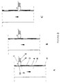
- ratchet (1) with a support (2), engaged to a strip (3) by means of holes or drills (4) with an ratchet element (5) sliding over said strip (3) pushed by a spring (6).
- This mechanism being mounted on a fixed shape (7), acting and fixing another moving shape (8).
- the ratchet (1) comprises an element (5), prefrably solid, machined, provided with a latch (9), and a flat end portion (10), and is pushed by means of a spring (6) or similar, said spring (6) exerting a pressure over said flat portion against the moving shape (8) surface (11), which is to be secured when the ratchet (1) is inserted into one of the strip (3) holes (4), said strip being fastened by any known system to said mobile shape (8).
- This flat part (10) is intended to act as a stop to allow for the ratchet (1) element (5) to be inserted in the perforated strip (3) and ensure a correct operation of the latch (9) even in the case that there is a gap between both shapes and to get a maximum shearing strength caused by the strip (3) engaging action, since said strip bears the whole weight of the moving shape (8) plus the weight of the load.
- the ratchet is guided by a supporting element (2), preferably solid, machined up to said strip (3) in order to ensure its mechanical strength against any strains in the assembly caused by stresses created during engaging action.
- the perforated strip (3) comprises a series of through holes (4).
- Said strip (3) may be provided with holes for the connection to shape by means of rivets, welding, etc.
- the holes (4) having the preferred configuration as shown in the figures, have a flat portion (12) to act on the latch (9) element (5) and a half circle portion (13) to serve as support for the engaging element.
- the perforated strip (3) is fastened to the shape (8), leaving a small gap as shown in the figures. This gap is intended to allow for the strip (3) to be supported on the element with a wide safety margin when the safety ratchet (1) element (5) is inserted into engagement holes (4).
- the latch system (9) and the insertion of said latch in the strip holes (3) is self adjustable relative to possible gaps between the interior tubular shape (8) moving upwards and the exterior shape (7).
- This self adjustment is produced when the flat end (10) of the ratchet (1) abuts onto said shape surface (11), always having the same distance between the latch end (9) and the contact line of said latch with the strip (3), thus ensuring a correct system operation.
Landscapes
- Engineering & Computer Science (AREA)
- General Engineering & Computer Science (AREA)
- Mechanical Engineering (AREA)
- Emergency Lowering Means (AREA)
- Burglar Alarm Systems (AREA)
- Casings For Electric Apparatus (AREA)
- Telephone Function (AREA)
- Portable Nailing Machines And Staplers (AREA)
- Aiming, Guidance, Guns With A Light Source, Armor, Camouflage, And Targets (AREA)
- Safety Valves (AREA)
Claims (3)
- Befestigungs- und Sicherheitsvorrichtung versehen mit einer Ratsche (1), welche auf einer befestigten Form (7) montiert ist, wobei die besagte Ratsche mit einem, von einer Feder (6) betätigten Ratschenelement (5) ausgestattet ist, sich das besagte Ratschenelement (5) mittels Verlagerung einer beweglichen Form (8) in Bezug auf die befestigte Form (7) in die Löcher (4) einpasst und die besagte Vorrichtung Aufwärtsbewegungen der besagten beweglichen Form (8) zulässt und Abwärtsbewegungen der besagten beweglichen Form (8) unterbindet, dadurch gekennzeichnet, dass die besagten Löcher (4) in ein Band (3) eingearbeitet sind, welches an der besagten beweglichen Form (8) befestigt ist, wobei zwischen dem besagten perforierten Band (3) und der besagten beweglichen Form (8) ein kleiner Zwischenraum vorhanden ist, und dass das besagte perforierte Band (3) in ein Halterungselement (2) eingebaut ist.
- Befestigungs- und Sicherheitsvorrichtung nach Anspruch 1, dadurch gekennzeichnet, dass, die es sich bei den besagten Löchern (4) um Durchgangslöcher mit einem flachen Abschnitt (12) und einem halbkreisförmigen Abschnitt (13) handelt.
- Befestigungs- und Sicherheitsvorrichtung nach Anspruch 1, dadurch gekennzeichnet, dass wenn sich das besagte Ratschenelement (5) in eines der besagten Löcher (4) einpasst, das besagte Ratschenelement (5) durch die Betätigung der besagten Feder (6) in das besagte perforierte Band (3) eingefügt wird bis es die Oberfläche (11) der besagten beweglichen Form (8) erreicht hat.
Applications Claiming Priority (3)
| Application Number | Priority Date | Filing Date | Title |
|---|---|---|---|
| ES9700039 | 1997-02-25 | ||
| ES009700398A ES2143360B1 (es) | 1997-02-25 | 1997-02-25 | Mecanismo de fijacion y seguridad |
| PCT/ES1998/000033 WO1998038432A1 (es) | 1997-02-25 | 1998-02-17 | Mecanismo de fijacion y seguridad |
Publications (2)
| Publication Number | Publication Date |
|---|---|
| EP0899467A1 EP0899467A1 (de) | 1999-03-03 |
| EP0899467B1 true EP0899467B1 (de) | 2004-01-28 |
Family
ID=8298391
Family Applications (1)
| Application Number | Title | Priority Date | Filing Date |
|---|---|---|---|
| EP98902746A Expired - Lifetime EP0899467B1 (de) | 1997-02-25 | 1998-02-17 | Sicherheits- und befestigungsmechanismus |
Country Status (6)
| Country | Link |
|---|---|
| US (1) | US6398445B1 (de) |
| EP (1) | EP0899467B1 (de) |
| AT (1) | ATE258656T1 (de) |
| DE (1) | DE69821297T2 (de) |
| ES (2) | ES2143360B1 (de) |
| WO (1) | WO1998038432A1 (de) |
Families Citing this family (21)
| Publication number | Priority date | Publication date | Assignee | Title |
|---|---|---|---|---|
| US6854694B1 (en) * | 2003-11-03 | 2005-02-15 | Wayne Van Etten | Tube retainer |
| US9790708B2 (en) * | 2004-02-24 | 2017-10-17 | D & D Group Pty. Ltd. | Magnetic latch |
| US20070000714A1 (en) * | 2005-06-29 | 2007-01-04 | Ching-Yao Lin | Assembling structure of a frame of a cart for use by handicapped and elderly persons |
| US7520542B1 (en) * | 2006-09-18 | 2009-04-21 | Ecp Family Properties, Llc | Childproof gate latch |
| US8104987B2 (en) * | 2009-06-25 | 2012-01-31 | Johnson Health Tech Co. Ltd. | Self-locating engagement pin locking and unlocking apparatus |
| US8667875B2 (en) * | 2011-05-31 | 2014-03-11 | Robert Bosch Gmbh | Accessory retention device for a rotary impact tool |
| US8662794B2 (en) | 2011-07-27 | 2014-03-04 | Hubbell Incorporated | Helical pile adapter |
| US20140215924A1 (en) * | 2011-08-17 | 2014-08-07 | Safergate Group Pty Ltd | Gate latch |
| US8641328B2 (en) | 2012-01-20 | 2014-02-04 | Hubbell Incorporated | Alignment window for drive tool assembly |
| US20230374858A1 (en) * | 2012-07-24 | 2023-11-23 | Little Giant Ladder Systems, Llc | Adjustable ladders, ladder components and related methods |
| US9707448B2 (en) | 2012-08-08 | 2017-07-18 | Hoist Fitness Systems, Inc. | Exercise machine with movable user support |
| CN110185379B (zh) | 2013-09-06 | 2022-06-24 | 小巨人梯具系统有限公司 | 梯子 |
| CN104912884B (zh) * | 2015-06-18 | 2017-12-19 | 昆山泓杰电子股份有限公司 | 可自锁型自由伸缩立柱机构 |
| US10066759B1 (en) * | 2016-04-04 | 2018-09-04 | Bnsf Railway Company | Locking / indexing pin |
| US10662686B2 (en) | 2016-09-30 | 2020-05-26 | Barrette Outdoor Living, Inc. | Magnetic safety gate latch |
| CN106926889B (zh) * | 2017-03-15 | 2024-01-09 | 闵远超 | 收合材积小的婴儿车架 |
| US10919556B2 (en) * | 2018-05-09 | 2021-02-16 | B&B Steel Products | Stackable and rollable carts and processes for assembling same |
| US11291883B2 (en) | 2019-12-26 | 2022-04-05 | Nautilus, Inc. | Tilt-enabled bike with tilt-disabling mechanism |
| CN111270964B (zh) * | 2020-01-20 | 2021-07-20 | 重庆峨克门窗幕墙工程有限公司 | 一种耐火窗 |
| CN112376883A (zh) * | 2020-11-17 | 2021-02-19 | 浙江铠甲建筑科技有限公司 | 一种脚手架自动爬升装置 |
| US20250127301A1 (en) * | 2023-10-24 | 2025-04-24 | Vertiv Corporation | Shelf safety pin for cabinet |
Family Cites Families (9)
| Publication number | Priority date | Publication date | Assignee | Title |
|---|---|---|---|---|
| US2630128A (en) * | 1950-02-18 | 1953-03-03 | Raymond W Slater | Telescoping and adjustable crutch |
| US4113221A (en) * | 1977-05-27 | 1978-09-12 | Cramer Industries, Inc. | Locking device |
| US4183566A (en) * | 1978-03-06 | 1980-01-15 | Hercules Industries, Inc. | Seal lock |
| US4183565A (en) * | 1978-08-28 | 1980-01-15 | Norris Industries, Inc. | Latch bolt locking mechanism for fire door locksets |
| US4278120A (en) * | 1978-10-05 | 1981-07-14 | Hi Shear Corporation | Safety bolt |
| ES245236Y (es) * | 1979-08-24 | 1980-06-16 | Cierre de golpe perfeccionado para ventanas | |
| US4602890A (en) * | 1985-02-22 | 1986-07-29 | Randall Equipment Company | Ratchet assembly and snap lock mechanism therefor |
| US4842311A (en) * | 1987-08-03 | 1989-06-27 | Creative Light & Sound Corporation | Safety latch |
| US6050740A (en) * | 1998-07-20 | 2000-04-18 | Dixie Electrical Manufacturing Company | Combined lockdog and kelly bar adapter |
-
1997
- 1997-02-25 ES ES009700398A patent/ES2143360B1/es not_active Expired - Fee Related
-
1998
- 1998-02-17 DE DE69821297T patent/DE69821297T2/de not_active Expired - Fee Related
- 1998-02-17 AT AT98902746T patent/ATE258656T1/de not_active IP Right Cessation
- 1998-02-17 WO PCT/ES1998/000033 patent/WO1998038432A1/es not_active Ceased
- 1998-02-17 EP EP98902746A patent/EP0899467B1/de not_active Expired - Lifetime
- 1998-02-17 ES ES98902746T patent/ES2218804T3/es not_active Expired - Lifetime
- 1998-10-23 US US09/178,261 patent/US6398445B1/en not_active Expired - Fee Related
Also Published As
| Publication number | Publication date |
|---|---|
| ATE258656T1 (de) | 2004-02-15 |
| US6398445B1 (en) | 2002-06-04 |
| DE69821297T2 (de) | 2004-10-21 |
| ES2143360A1 (es) | 2000-05-01 |
| WO1998038432A1 (es) | 1998-09-03 |
| EP0899467A1 (de) | 1999-03-03 |
| DE69821297D1 (de) | 2004-03-04 |
| ES2218804T3 (es) | 2004-11-16 |
| ES2143360B1 (es) | 2000-12-01 |
Similar Documents
| Publication | Publication Date | Title |
|---|---|---|
| EP0899467A1 (de) | Sicherheits- und befestigungsmechanismus | |
| EP0404745B1 (de) | Teleskopische Ladungsstange | |
| EP2299032B1 (de) | Druck anwendender, teleskopischer Abstandshalter | |
| AU2002311256B2 (en) | Collapsible ladder | |
| US11306497B2 (en) | Support post | |
| DE69109855T2 (de) | Sicherheitsverankerung zum reglen der sicherungsseilausgabe. | |
| US4057935A (en) | Quick release mechanism for window guard or the like | |
| US5743355A (en) | Retractable ladder | |
| JP4977148B2 (ja) | 安全杭 | |
| US4751851A (en) | Mechanical cable control device with manual adjustment | |
| IT9021386A1 (it) | Sedile di autoveicolo | |
| EP2314914B1 (de) | Montagevorrichtung für eine Einbauleuchte | |
| US3990207A (en) | Tiedown device | |
| US7413166B2 (en) | Commercial lifting device-jack stand frame locking mechanism | |
| US5975241A (en) | Pump jack handle assembly | |
| WO1999041509A1 (de) | Teleskopstütze | |
| US4842311A (en) | Safety latch | |
| US6176468B1 (en) | Safety locking mechanism for a mechanical lifting jack | |
| AU2002307930B2 (en) | Safety line traveller and support | |
| GB2081357A (en) | Multipurpose ladder | |
| EP1743615A1 (de) | Badewannenlifter | |
| US5931446A (en) | Pole jack apparatus | |
| GB2277952A (en) | Catch mechanism | |
| CA2234885C (en) | Safety locking mechanism for a mechanical lifting jack | |
| JPS5822607A (ja) | 動力操作チヤツク |
Legal Events
| Date | Code | Title | Description |
|---|---|---|---|
| PUAI | Public reference made under article 153(3) epc to a published international application that has entered the european phase |
Free format text: ORIGINAL CODE: 0009012 |
|
| AK | Designated contracting states |
Kind code of ref document: A1 Designated state(s): AT BE CH DE ES FR GB GR IT LI NL PT |
|
| 17P | Request for examination filed |
Effective date: 19990326 |
|
| 17Q | First examination report despatched |
Effective date: 20020506 |
|
| GRAH | Despatch of communication of intention to grant a patent |
Free format text: ORIGINAL CODE: EPIDOS IGRA |
|
| GRAS | Grant fee paid |
Free format text: ORIGINAL CODE: EPIDOSNIGR3 |
|
| GRAA | (expected) grant |
Free format text: ORIGINAL CODE: 0009210 |
|
| AK | Designated contracting states |
Kind code of ref document: B1 Designated state(s): AT BE CH DE ES FR GB GR IT LI NL PT |
|
| PG25 | Lapsed in a contracting state [announced via postgrant information from national office to epo] |
Ref country code: LI Free format text: LAPSE BECAUSE OF FAILURE TO SUBMIT A TRANSLATION OF THE DESCRIPTION OR TO PAY THE FEE WITHIN THE PRESCRIBED TIME-LIMIT Effective date: 20040128 Ref country code: CH Free format text: LAPSE BECAUSE OF FAILURE TO SUBMIT A TRANSLATION OF THE DESCRIPTION OR TO PAY THE FEE WITHIN THE PRESCRIBED TIME-LIMIT Effective date: 20040128 Ref country code: AT Free format text: LAPSE BECAUSE OF FAILURE TO SUBMIT A TRANSLATION OF THE DESCRIPTION OR TO PAY THE FEE WITHIN THE PRESCRIBED TIME-LIMIT Effective date: 20040128 |
|
| REG | Reference to a national code |
Ref country code: GB Ref legal event code: FG4D |
|
| REG | Reference to a national code |
Ref country code: CH Ref legal event code: EP |
|
| PG25 | Lapsed in a contracting state [announced via postgrant information from national office to epo] |
Ref country code: BE Free format text: LAPSE BECAUSE OF NON-PAYMENT OF DUE FEES Effective date: 20040228 |
|
| REF | Corresponds to: |
Ref document number: 69821297 Country of ref document: DE Date of ref document: 20040304 Kind code of ref document: P |
|
| PG25 | Lapsed in a contracting state [announced via postgrant information from national office to epo] |
Ref country code: GR Free format text: LAPSE BECAUSE OF FAILURE TO SUBMIT A TRANSLATION OF THE DESCRIPTION OR TO PAY THE FEE WITHIN THE PRESCRIBED TIME-LIMIT Effective date: 20040428 Ref country code: GB Free format text: LAPSE BECAUSE OF NON-PAYMENT OF DUE FEES Effective date: 20040428 |
|
| REG | Reference to a national code |
Ref country code: CH Ref legal event code: PL |
|
| BERE | Be: lapsed |
Owner name: S.A. *VMB ESPANOLA Effective date: 20040228 |
|
| PG25 | Lapsed in a contracting state [announced via postgrant information from national office to epo] |
Ref country code: NL Free format text: LAPSE BECAUSE OF NON-PAYMENT OF DUE FEES Effective date: 20040901 |
|
| NLV4 | Nl: lapsed or anulled due to non-payment of the annual fee |
Effective date: 20040901 |
|
| REG | Reference to a national code |
Ref country code: ES Ref legal event code: FG2A Ref document number: 2218804 Country of ref document: ES Kind code of ref document: T3 |
|
| ET | Fr: translation filed | ||
| PLBE | No opposition filed within time limit |
Free format text: ORIGINAL CODE: 0009261 |
|
| STAA | Information on the status of an ep patent application or granted ep patent |
Free format text: STATUS: NO OPPOSITION FILED WITHIN TIME LIMIT |
|
| GBPC | Gb: european patent ceased through non-payment of renewal fee |
Effective date: 20040428 |
|
| 26N | No opposition filed |
Effective date: 20041029 |
|
| PG25 | Lapsed in a contracting state [announced via postgrant information from national office to epo] |
Ref country code: IT Free format text: LAPSE BECAUSE OF NON-PAYMENT OF DUE FEES Effective date: 20050217 |
|
| PGFP | Annual fee paid to national office [announced via postgrant information from national office to epo] |
Ref country code: ES Payment date: 20050328 Year of fee payment: 8 |
|
| PGFP | Annual fee paid to national office [announced via postgrant information from national office to epo] |
Ref country code: DE Payment date: 20050426 Year of fee payment: 8 |
|
| PGFP | Annual fee paid to national office [announced via postgrant information from national office to epo] |
Ref country code: FR Payment date: 20050427 Year of fee payment: 7 |
|
| PG25 | Lapsed in a contracting state [announced via postgrant information from national office to epo] |
Ref country code: ES Free format text: LAPSE BECAUSE OF NON-PAYMENT OF DUE FEES Effective date: 20060218 |
|
| PG25 | Lapsed in a contracting state [announced via postgrant information from national office to epo] |
Ref country code: DE Free format text: LAPSE BECAUSE OF NON-PAYMENT OF DUE FEES Effective date: 20060901 |
|
| REG | Reference to a national code |
Ref country code: ES Ref legal event code: FD2A Effective date: 20060218 |
|
| PG25 | Lapsed in a contracting state [announced via postgrant information from national office to epo] |
Ref country code: PT Free format text: LAPSE BECAUSE OF NON-PAYMENT OF DUE FEES Effective date: 20040628 |
|
| REG | Reference to a national code |
Ref country code: FR Ref legal event code: ST Effective date: 20080229 |
|
| PG25 | Lapsed in a contracting state [announced via postgrant information from national office to epo] |
Ref country code: FR Free format text: LAPSE BECAUSE OF NON-PAYMENT OF DUE FEES Effective date: 20040301 |