EP0899458B1 - Hydraulikpumpenanlage - Google Patents
Hydraulikpumpenanlage Download PDFInfo
- Publication number
- EP0899458B1 EP0899458B1 EP19980306044 EP98306044A EP0899458B1 EP 0899458 B1 EP0899458 B1 EP 0899458B1 EP 19980306044 EP19980306044 EP 19980306044 EP 98306044 A EP98306044 A EP 98306044A EP 0899458 B1 EP0899458 B1 EP 0899458B1
- Authority
- EP
- European Patent Office
- Prior art keywords
- valve
- valve bore
- annular retainer
- bore
- spool
- Prior art date
- Legal status (The legal status is an assumption and is not a legal conclusion. Google has not performed a legal analysis and makes no representation as to the accuracy of the status listed.)
- Expired - Lifetime
Links
- 239000012530 fluid Substances 0.000 claims description 17
- 230000006835 compression Effects 0.000 description 3
- 238000007906 compression Methods 0.000 description 3
- 238000005086 pumping Methods 0.000 description 3
- 239000000725 suspension Substances 0.000 description 2
- 230000008878 coupling Effects 0.000 description 1
- 238000010168 coupling process Methods 0.000 description 1
- 238000005859 coupling reaction Methods 0.000 description 1
- 230000000694 effects Effects 0.000 description 1
- 230000007246 mechanism Effects 0.000 description 1
- 230000037452 priming Effects 0.000 description 1
Images
Classifications
-
- F—MECHANICAL ENGINEERING; LIGHTING; HEATING; WEAPONS; BLASTING
- F04—POSITIVE - DISPLACEMENT MACHINES FOR LIQUIDS; PUMPS FOR LIQUIDS OR ELASTIC FLUIDS
- F04C—ROTARY-PISTON, OR OSCILLATING-PISTON, POSITIVE-DISPLACEMENT MACHINES FOR LIQUIDS; ROTARY-PISTON, OR OSCILLATING-PISTON, POSITIVE-DISPLACEMENT PUMPS
- F04C14/00—Control of, monitoring of, or safety arrangements for, machines, pumps or pumping installations
- F04C14/24—Control of, monitoring of, or safety arrangements for, machines, pumps or pumping installations characterised by using valves controlling pressure or flow rate, e.g. discharge valves or unloading valves
- F04C14/26—Control of, monitoring of, or safety arrangements for, machines, pumps or pumping installations characterised by using valves controlling pressure or flow rate, e.g. discharge valves or unloading valves using bypass channels
-
- Y—GENERAL TAGGING OF NEW TECHNOLOGICAL DEVELOPMENTS; GENERAL TAGGING OF CROSS-SECTIONAL TECHNOLOGIES SPANNING OVER SEVERAL SECTIONS OF THE IPC; TECHNICAL SUBJECTS COVERED BY FORMER USPC CROSS-REFERENCE ART COLLECTIONS [XRACs] AND DIGESTS
- Y10—TECHNICAL SUBJECTS COVERED BY FORMER USPC
- Y10T—TECHNICAL SUBJECTS COVERED BY FORMER US CLASSIFICATION
- Y10T137/00—Fluid handling
- Y10T137/2496—Self-proportioning or correlating systems
- Y10T137/2559—Self-controlled branched flow systems
- Y10T137/2574—Bypass or relief controlled by main line fluid condition
- Y10T137/2579—Flow rate responsive
- Y10T137/2594—Choke
-
- Y—GENERAL TAGGING OF NEW TECHNOLOGICAL DEVELOPMENTS; GENERAL TAGGING OF CROSS-SECTIONAL TECHNOLOGIES SPANNING OVER SEVERAL SECTIONS OF THE IPC; TECHNICAL SUBJECTS COVERED BY FORMER USPC CROSS-REFERENCE ART COLLECTIONS [XRACs] AND DIGESTS
- Y10—TECHNICAL SUBJECTS COVERED BY FORMER USPC
- Y10T—TECHNICAL SUBJECTS COVERED BY FORMER US CLASSIFICATION
- Y10T137/00—Fluid handling
- Y10T137/598—With repair, tapping, assembly, or disassembly means
- Y10T137/6065—Assembling or disassembling reciprocating valve
Definitions
- This invention relates a hydraulic apparatus comprising a housing having a valve bore with first and second ends, a spool valve disposed in the valve bore and slidable between a first and second position, and a discharge connector having threads on an outer circumference thereof for engaging internal threads disposed on said first end of said valve bore, said discharge connector forming a fluid passage for communicating fluid through said first end of said valve bore.
- Hydraulic pumps are well known to those skilled in the hydraulics art, as are many forms of actuators having sliding valves therein. Commonly these valves are used to control fluid flow within the pump, actuator etc.
- the valve in EP-A-0 505 033, in common with the present invention, serves to relieve the pressure at the discharge connector that leads to the steering gear.
- the valves are commonly located within a valve bore and are free to slide between at least two predetermined positions. Additionally, the bore is generally manufactured to allow the valve to slide completely out at least one end of the bore. This accommodates assembly, and where necessary, service of the valve assembly.
- the present invention therefore seeks to provide a hydraulic apparatus that can be oriented to have a vertical valve bore yet would not require service of the valve assembly during servicing as a result of its inadvertent removal.
- annular retainer is disposed in the valve bore between the first position of said spool valve and the discharge connector, the annular retainer having an outer periphery sized for interference fit engagement with said valve bore for retaining the spool valve within the valve bore when the discharge connector is removed from said first end of said valve bore.
- the annular retainer positively retains the spool valve within the valve bore in the absence of the discharge connector, allowing service of the discharge connector and any associated components, such as fluid line and couplings, without requiring inadvertent service of the spool valve.
- the preferred embodiment of the invention further comprises a discharge port nozzle attached to the discharge connector, the annular retainer having an inner periphery sized for interference fit with the discharge port nozzle.
- the outer periphery of the annular retainer includes a plurality of protuberances projecting outward to engage said valve bore, thereby creating said interference fit.
- a rotary vane hydraulic power steering pump supplies pressurized fluid to an automotive vehicle steering gear.
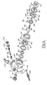
- the pump includes a housing 10 defining a cylindrical space 12 containing the pumping elements, a bore 14 having first and second ends 15, 17 containing a flow control valve and related components and a diffuser passage 18.
- the housing includes at least three bosses 20-22, each having a cylindrical hole adapted to receive a mechanical attachment such as a bolt, which can be threaded directly to the engine block of the vehicle. In this way, the conventional bracket usually used to support a power steering pump located in position to be driven by a belt from the engine crankshaft can be eliminated.
- the components that pump hydraulic fluid from a reservoir to the steering gear are rotatably supported on a shaft 24, driven by an endless drive belt from an engine and rotatably connected by a splined connection to a rotor 26 fixed in position on the shaft by a snap ring 28.
- the rotor has ten radially sliding vanes 30, held in contact with the inner surface of a cam ring 32 having two arcuate zones extending angularly in rise or inlet quadrants and two zones of lesser radial size extending angularly in fall or outlet quadrants mutually separated by the inlet quadrants.
- a lower pressure plate 34 and an upper pressure plate 36 are fixed in position radially with respect to the cam 32 by alignment pins 38.
- arcuate outlet ports 40, 42 communicating with an outlet port opening to the flow control valve bore 14, inlet ports 44, 46 and arcuate passages 48, 50 for use in cold starting priming.
- the lower pressure plate has inlet ports 56, 54 formed through its thickness, outlet ports 58, 60 and arcuate flow passages 62, 64 hydraulically connected to passages 48, 50.
- a wire retaining ring 66 seats within a recess at the end of the pump housing to hold in position a pump cover 68.
- Bushing 70 supports shaft 24 on a recess in the inner surface of the cover. Seal 72 prevents the passage of hydraulic fluid.
- the opposite end of the rotor shaft is supported rotatably in a bushing 74, which is supported on the housing; a shaft seal 76 prevents flow of hydraulic fluid from the pumping chambers.
- a shaft seal 76 prevents flow of hydraulic fluid from the pumping chambers.
- an inner seal 78 Located adjacent the lower pressure plate on the opposite side from the cam are an inner seal 78, an outer seal 80, and a Belleville spring 82, which develops an axial force tending to force mutually adjacent surfaces of the various components into abutting contact.
- a discharge port nozzle 84 Located within bore 14 are a discharge port nozzle 84, integrally formed with a discharge connector 88, a seal 86,and an annular retainer ring 90.
- the discharge connector 88 has a threaded portion 89 for engagement with a threaded portion 92 of the valve bore 14.
- a relief valve spool 94 located within bore 14 is a relief valve spool 94, a coiled compression spring, ball, and ball seat 96 and a larger compression spring 98 urging spool 94 toward a first position where the flow control valve is closed corresponding to low pump speed operation.
- a seal 100 and plug 102 close the adjacent end of the bore mechanically and hydraulically.
- a tube assembly 104 connects a tube carrying fluid from the steering gear to the pump housing, through which it passes in suitable ports to the pumping chamber.
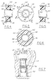
- the annular retainer ring 90 is disposed within the bore 14 between a first position of the valve spool 94 and the inner end of the discharge connector 88.
- the annular retainer 90 includes an outer periphery 130 sized for interference fit engagement with the bore 14.
- the outer periphery of the annular retainer includes a plurality of protuberances 132 projecting radially outward for engagement with the bore 14.
- the protuberances may be tapered, having a low end 134 of the taper adjacent to the valve spool 94 and the high end 136 adjacent to the discharge connector 88.
- the annular retainer 90 also includes an inner periphery 140 sized for interference fit engagement with the discharge port nozzle 84.
- the inner periphery 140 may include flats 142 protruding inwardly from the otherwise circular periphery of the annular retainer. Depending on the amount of interference desired, small flats may be formed just adjacent to the spool valve 94, or if greater interference is desired, larger flats may extend further into the inner periphery 140 of the annular retainer 90.
- the amount of taper on the protuberances 132 and the size of the flats 142 can be varied so as to create a relationship permitting the removal of the discharge port nozzle without causing the annular retainer to be removed from the bore 14. This is accomplished by the combination of greater surface area contacted by the outer diameter than the inner diameter together with a sufficient taper on the protuberances 132 to create a higher retaining force than that created by the interference between the flats and the discharge port nozzle. This is particularly advantageous where automated assembly equipment is used and the retainer 90 must stay on the discharge port nozzle until it is assembled into the valve bore.
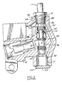
- Nozzle 84 has an axially directed passage 114, which continually connects port 112 to the pressure tube 116, which carries high pressure hydraulic fluid to the steering gear from the pump.
- the flow rate through port 112 is proportional to the speed of the pump shaft 24 and to the speed of the engine to which that shaft is connected. Directing fluid flow into passage 114 produces a pressure drop relative to pressure at port 112. Pressure downstream of aperture 114, the steering system pressure, is fed back in passage 115 to the end of the relief valve spool 94 contacted by spring 98. A force resulting from the feedback pressure adds to the spring force on the spool.
- hydraulic system pressure in port 112 increases, thereby forcing relief valve spool 94, against the effect of compression spring 98 and the feedback pressure, away from the first position toward a second position (as shown in Figure 7) where additional fluid flow is bled back to a fluid reservoir through the diffuser passage 18.
- This operating condition may also be referred to as the high speed operating mode, as it occurs when the pump operates at high speeds.
- the spring 98 urges the relief valve spool 94 against the annular retainer 90.
- the annular retainer 90 positively resists sliding of the relief valve spool 94, so as to prevent inadvertent disassembly of the relief valve spool 94.
- a hooked object may be inserted in bore 14 to forcibly remove the retainer 90 if servicing the relief valve spool 94 is specifically desired.
Landscapes
- Engineering & Computer Science (AREA)
- Physics & Mathematics (AREA)
- Fluid Mechanics (AREA)
- Mechanical Engineering (AREA)
- General Engineering & Computer Science (AREA)
- Details And Applications Of Rotary Liquid Pumps (AREA)
- Rotary Pumps (AREA)
Claims (8)
- Hydraulische Vorrichtung, folgendes aufweisend:gekennzeichnet durchein Gehäuse (10) mit einer Ventilbohrung (14) darin, wobei besagte Ventilbohrung ein erstes und ein zweites Ende (15, 17) aufweist;einen in besagter Ventilbohrung (14) angeordneten und gleitend zwischen einer ersten und einer zweiten Stellung bewegbaren Ventilschieber (94); undeinen Auslaßverbinder (88) mit einem Gewinde an einem Außenumfang desselben, das in ein an besagtem erstem Ende der besagten Ventilbohrung (14) angeordnetes Innengewinde eingreift, wobei besagter Auslaßverbinder (88) einen Strömungskanal bildet, durch den Flüssigkeit durch besagtes erstes Ende (15) der besagten Ventilbohrung strömen kann;
einen in besagter Ventilbohrung (14) zwischen der besagten ersten Stellung des besagten Ventilschiebers (94) und besagtem Auslaßverbinder (88) angeordneten Haltering (90), wobei besagter Haltering (90) einen Außenumfang (130) aufweist, der so bemessen ist, daß er mit Pressung in Eingriff mit besagter Ventilbohrung (14) steht, so daß er besagten Ventilschieber (94) in besagter Ventilbohrung (14) festhält, wenn besagter Auslaßverbinder (88) von besagtem erstem Ende der besagten Ventilbohrung entfernt wird. - Vorrichtung nach Anspruch 1, außerdem eine an besagtem Auslaßverbinder (88) befestigte Auslaßöffnungsdüse (84) aufweisend, wobei besagter Haltering (90) einen Innenumfang (140) aufweist, der so bemessen ist, daß er mit Pressung an besagter Auslaßöffnungsdüse (84) anliegt.
- Vorrichtung nach Anspruch 1 oder 2, worin besagter Außenumfang (130) des besagten Halteringes (90) mehrere nach außen abstehende Vorsprünge (132) aufweist, die mit der Ventilbohrung (14) in Eingriff treten und so eine Preßpassung bilden.
- Vorrichtung nach Anspruch 3, worin besagte Vorsprünge (132). eine äußere Kegelform aufweisen, mit einem dem Ventilschieber (94) zugewandten niedrigen Ende (134) und einem dem Auslaßverbinder (88) zugekehrten hohen Ende (134).
- Vorrichtung nach Anspruch 2, 3 oder 4, worin besagter Außenumfang (140) des besagten Halteringes (90) wenigstens eine Abflachung (142) zur Erzeugung einer Preßpassung mit besagter Auslaßöffnungsdüse (84) aufweist.
- Vorrichtung nach Anspruch 5, worin besagte Abflachung (142) nur in unmittelbarer Nähe des besagten Ventilschiebers (94) von besagtem Innenumfang (140) aus nach innen absteht.
- Vorrichtung nach einem beliebigen der Ansprüche 2 bis 6, worin besagte Preßpassung zwischen besagtem Außenumfang (130) des besagten Halteringes (90) und besagter Ventilbohrung (14) eine größere Haltekraft erzeugt als besagte Preßpassung zwischen besagtem Innenumfang (140) des besagten Halteringes (90) und besagter Auslaßöffnungsdüse (84), so daß besagter Auslaßverbinder (88) und besagte Auslaßöffnungsdüse (84) aus besagter Ventilbohrung (14) entfernt werden können, ohne dabei auch den besagten Haltering (90) aus der besagten Ventilbohrung (14) zu entfernen.
- Hydraulische Pumpe zur Lieferung von Flüssigkeit an ein Lenkgetriebe in einem Kraftfahrzeug, mit einer Vorrichtung nach einem beliebigen der vorangehenden Ansprüche, worin besagter Ventilschieber (94) Teil eines Druckentlastungsventils zur Senkung des Hydraulikdruckes am Auslaßverbinder (88) ist.
Applications Claiming Priority (2)
| Application Number | Priority Date | Filing Date | Title |
|---|---|---|---|
| US08/921,077 US5887612A (en) | 1997-08-29 | 1997-08-29 | Hydraulic pump apparatus |
| US921077 | 1997-08-29 |
Publications (2)
| Publication Number | Publication Date |
|---|---|
| EP0899458A1 EP0899458A1 (de) | 1999-03-03 |
| EP0899458B1 true EP0899458B1 (de) | 2003-12-10 |
Family
ID=25444885
Family Applications (1)
| Application Number | Title | Priority Date | Filing Date |
|---|---|---|---|
| EP19980306044 Expired - Lifetime EP0899458B1 (de) | 1997-08-29 | 1998-07-29 | Hydraulikpumpenanlage |
Country Status (3)
| Country | Link |
|---|---|
| US (1) | US5887612A (de) |
| EP (1) | EP0899458B1 (de) |
| DE (1) | DE69820360T2 (de) |
Families Citing this family (8)
| Publication number | Priority date | Publication date | Assignee | Title |
|---|---|---|---|---|
| JP2004166161A (ja) * | 2002-02-08 | 2004-06-10 | Ricoh Co Ltd | 通信装置、通信装置の制御方法、プログラム及び記録媒体 |
| US20050186094A1 (en) * | 2002-09-03 | 2005-08-25 | Visteon Global Technologies, Inc. | Power steering pump having electronic bypass control |
| US7350616B2 (en) * | 2002-09-03 | 2008-04-01 | Automotive Components Holdings, Llc | Power steering pump having electronic bypass control |
| US20040040595A1 (en) * | 2002-09-03 | 2004-03-04 | Visteon Global Technologies, Inc. | Power steering pump comprising cartridge flow control assembly |
| US6899528B2 (en) * | 2002-09-03 | 2005-05-31 | Visteon Global Technologies, Inc. | Power steering pump |
| US6666670B1 (en) | 2003-05-22 | 2003-12-23 | Visteon Global Technologies, Inc. | Power steering pump |
| US6896298B2 (en) * | 2003-08-01 | 2005-05-24 | Paccar Inc | Conduit coupling assembly |
| US20050062584A1 (en) * | 2003-09-24 | 2005-03-24 | Broadcom Corporation | High-linearity switched-resistor network for programmability |
Family Cites Families (7)
| Publication number | Priority date | Publication date | Assignee | Title |
|---|---|---|---|---|
| US3667725A (en) * | 1968-08-07 | 1972-06-06 | Balon Corp | Unstressed seats for between flange valves |
| JPS6088283A (ja) * | 1983-10-18 | 1985-05-18 | Toyoda Mach Works Ltd | 動力舵取装置用流量制御装置 |
| US5161959A (en) * | 1991-03-11 | 1992-11-10 | Ford Motor Company | Viscosity sensitive hydraulic pump flow control |
| US5253842A (en) * | 1992-07-30 | 1993-10-19 | Lab Products, Inc. | Quick disconnect water valve assembly |
| US5339856A (en) * | 1993-11-08 | 1994-08-23 | Dresser-Rand Company | Valve retainer means, a method of forming the same, and a method of valve insertion therewith |
| US5467611A (en) * | 1994-11-07 | 1995-11-21 | General Motors Corporation | Two plate TXV block connector for automotive A/C system with common bolts and independently attachable sides |
| US5819777A (en) * | 1995-07-07 | 1998-10-13 | Unisia Jecs Corporation | Flow control device |
-
1997
- 1997-08-29 US US08/921,077 patent/US5887612A/en not_active Expired - Lifetime
-
1998
- 1998-07-29 DE DE1998620360 patent/DE69820360T2/de not_active Expired - Lifetime
- 1998-07-29 EP EP19980306044 patent/EP0899458B1/de not_active Expired - Lifetime
Also Published As
| Publication number | Publication date |
|---|---|
| EP0899458A1 (de) | 1999-03-03 |
| DE69820360T2 (de) | 2004-05-27 |
| US5887612A (en) | 1999-03-30 |
| DE69820360D1 (de) | 2004-01-22 |
Similar Documents
| Publication | Publication Date | Title |
|---|---|---|
| US20250314300A1 (en) | Hydraulic fluid pump and stuffing box assembly for same | |
| US5353755A (en) | Arrangement of variable valve timing control system on V-type engine | |
| US10443455B2 (en) | Variable valve timing control device | |
| EP0899458B1 (de) | Hydraulikpumpenanlage | |
| CN109469609B (zh) | 机油泵及发动机润滑系统 | |
| US6499964B2 (en) | Integrated vane pump and motor | |
| JP7481254B2 (ja) | ポンプのピボットピンに一体化されたパニックバルブ | |
| US4599051A (en) | Vane type rotary pump | |
| US20040244838A1 (en) | Valve assembly | |
| US4400139A (en) | Oil pump | |
| EP1627149B1 (de) | Radialkolbenpumpe | |
| US4953582A (en) | Combined pressure regulator and relief valve having a single biasing means | |
| CN1112535C (zh) | 用于润滑泵的泵芯 | |
| WO1999039103A1 (en) | Pressure clamped hydraulic pump | |
| US9181909B2 (en) | Fuel pump retainer | |
| EP3284931B1 (de) | Druckregelventil mit flussdrehsicherung | |
| CN111379695A (zh) | 叶片泵 | |
| JPH10184483A (ja) | ポンプ装置 | |
| WO2022098360A1 (en) | Adaptable barrels for fuel injection | |
| US5271723A (en) | Engine driven oil pump | |
| US4990065A (en) | Plunger pump | |
| CN1133004C (zh) | 用于供给内燃机燃料的具有可拆装的开关阀的高压泵 | |
| US12480487B1 (en) | Fluid end of pump | |
| WO1997024530A1 (en) | Vane pump | |
| KR100435947B1 (ko) | 오일 펌프 커버에 로터실이 형성된 오일펌프 |
Legal Events
| Date | Code | Title | Description |
|---|---|---|---|
| PUAI | Public reference made under article 153(3) epc to a published international application that has entered the european phase |
Free format text: ORIGINAL CODE: 0009012 |
|
| AK | Designated contracting states |
Kind code of ref document: A1 Designated state(s): DE FR GB |
|
| AX | Request for extension of the european patent |
Free format text: AL;LT;LV;MK;RO;SI |
|
| 17P | Request for examination filed |
Effective date: 19990806 |
|
| AKX | Designation fees paid |
Free format text: DE FR GB |
|
| 17Q | First examination report despatched |
Effective date: 20020711 |
|
| GRAH | Despatch of communication of intention to grant a patent |
Free format text: ORIGINAL CODE: EPIDOS IGRA |
|
| RAP1 | Party data changed (applicant data changed or rights of an application transferred) |
Owner name: FORD GLOBAL TECHNOLOGIES, INC. |
|
| GRAS | Grant fee paid |
Free format text: ORIGINAL CODE: EPIDOSNIGR3 |
|
| GRAA | (expected) grant |
Free format text: ORIGINAL CODE: 0009210 |
|
| RAP1 | Party data changed (applicant data changed or rights of an application transferred) |
Owner name: FORD GLOBAL TECHNOLOGIES, LLC |
|
| AK | Designated contracting states |
Kind code of ref document: B1 Designated state(s): DE FR GB |
|
| REG | Reference to a national code |
Ref country code: GB Ref legal event code: FG4D |
|
| REF | Corresponds to: |
Ref document number: 69820360 Country of ref document: DE Date of ref document: 20040122 Kind code of ref document: P |
|
| ET | Fr: translation filed | ||
| PLBE | No opposition filed within time limit |
Free format text: ORIGINAL CODE: 0009261 |
|
| STAA | Information on the status of an ep patent application or granted ep patent |
Free format text: STATUS: NO OPPOSITION FILED WITHIN TIME LIMIT |
|
| 26N | No opposition filed |
Effective date: 20040913 |
|
| PGFP | Annual fee paid to national office [announced via postgrant information from national office to epo] |
Ref country code: GB Payment date: 20110622 Year of fee payment: 14 |
|
| PGFP | Annual fee paid to national office [announced via postgrant information from national office to epo] |
Ref country code: FR Payment date: 20110727 Year of fee payment: 14 |
|
| GBPC | Gb: european patent ceased through non-payment of renewal fee |
Effective date: 20120729 |
|
| REG | Reference to a national code |
Ref country code: FR Ref legal event code: ST Effective date: 20130329 |
|
| PG25 | Lapsed in a contracting state [announced via postgrant information from national office to epo] |
Ref country code: FR Free format text: LAPSE BECAUSE OF NON-PAYMENT OF DUE FEES Effective date: 20120731 Ref country code: GB Free format text: LAPSE BECAUSE OF NON-PAYMENT OF DUE FEES Effective date: 20120729 |
|
| PGFP | Annual fee paid to national office [announced via postgrant information from national office to epo] |
Ref country code: DE Payment date: 20150731 Year of fee payment: 18 |
|
| REG | Reference to a national code |
Ref country code: DE Ref legal event code: R082 Ref document number: 69820360 Country of ref document: DE Representative=s name: DOERFLER, THOMAS, DR.-ING., DE |
|
| REG | Reference to a national code |
Ref country code: DE Ref legal event code: R119 Ref document number: 69820360 Country of ref document: DE |
|
| PG25 | Lapsed in a contracting state [announced via postgrant information from national office to epo] |
Ref country code: DE Free format text: LAPSE BECAUSE OF NON-PAYMENT OF DUE FEES Effective date: 20170201 |