EP0899426A2 - Guide vane for a gas turbine - Google Patents
Guide vane for a gas turbine Download PDFInfo
- Publication number
- EP0899426A2 EP0899426A2 EP98114445A EP98114445A EP0899426A2 EP 0899426 A2 EP0899426 A2 EP 0899426A2 EP 98114445 A EP98114445 A EP 98114445A EP 98114445 A EP98114445 A EP 98114445A EP 0899426 A2 EP0899426 A2 EP 0899426A2
- Authority
- EP
- European Patent Office
- Prior art keywords
- guide vane
- projection
- platform
- face
- guide
- Prior art date
- Legal status (The legal status is an assumption and is not a legal conclusion. Google has not performed a legal analysis and makes no representation as to the accuracy of the status listed.)
- Granted
Links
- 230000002787 reinforcement Effects 0.000 claims description 8
- 239000002184 metal Substances 0.000 claims description 7
- 229920002430 Fibre-reinforced plastic Polymers 0.000 claims description 2
- 239000011151 fibre-reinforced plastic Substances 0.000 claims description 2
- 230000003014 reinforcing effect Effects 0.000 claims 1
- 238000012360 testing method Methods 0.000 description 8
- 239000004033 plastic Substances 0.000 description 4
- 229920003023 plastic Polymers 0.000 description 4
- 239000000853 adhesive Substances 0.000 description 3
- 230000001070 adhesive effect Effects 0.000 description 3
- 239000004918 carbon fiber reinforced polymer Substances 0.000 description 3
- 238000013016 damping Methods 0.000 description 3
- 230000000694 effects Effects 0.000 description 3
- 238000013461 design Methods 0.000 description 2
- 238000012938 design process Methods 0.000 description 2
- 238000001746 injection moulding Methods 0.000 description 2
- 238000011835 investigation Methods 0.000 description 2
- 238000004519 manufacturing process Methods 0.000 description 2
- 238000005259 measurement Methods 0.000 description 2
- 238000004026 adhesive bonding Methods 0.000 description 1
- 238000011161 development Methods 0.000 description 1
- 230000002349 favourable effect Effects 0.000 description 1
- 239000000463 material Substances 0.000 description 1
- 238000000034 method Methods 0.000 description 1
- 238000007789 sealing Methods 0.000 description 1
- 239000000243 solution Substances 0.000 description 1
Images


Classifications
-
- F—MECHANICAL ENGINEERING; LIGHTING; HEATING; WEAPONS; BLASTING
- F01—MACHINES OR ENGINES IN GENERAL; ENGINE PLANTS IN GENERAL; STEAM ENGINES
- F01D—NON-POSITIVE DISPLACEMENT MACHINES OR ENGINES, e.g. STEAM TURBINES
- F01D9/00—Stators
- F01D9/02—Nozzles; Nozzle boxes; Stator blades; Guide conduits, e.g. individual nozzles
- F01D9/04—Nozzles; Nozzle boxes; Stator blades; Guide conduits, e.g. individual nozzles forming ring or sector
- F01D9/042—Nozzles; Nozzle boxes; Stator blades; Guide conduits, e.g. individual nozzles forming ring or sector fixing blades to stators
Definitions
- the invention relates to a guide vane for a gas turbine, in particular a low-pressure turbine, with an airfoil located between an inner platform and an outer platform extends, the outer platform fastening means for attachment to a housing has, a guide vane segment from at least three guide vanes and a vane assembly.
- Guide vanes of low pressure turbines are made of metal and are in the development phase generally first soldered together into segments of three or six guide vanes.
- the guide vanes are on their outer platforms in a (engine) housing attached and releasably together on their inner platforms by metal clips or the like tense.
- the vibration behavior is due to the tension on the inner platforms the blades are improved.
- the use of the braces as an additional Components have the disadvantage of more complex assembly and higher costs.
- guide vanes made of mostly carbon fiber reinforced plastics are used and in so-called aerodynamic Cold "test benches are examined.
- Such guide vanes are considerably faster and less expensive to produce than corresponding guide vanes made of metal and are therefore used with preference in the preceding investigations.
- the guide vanes made of plastic are used at considerably lower temperatures (approx. 130 ° C.) than in the real one Operation, however, loaded with gas forces of the same order of magnitude as in the real engine.
- the problem here is the geometry of the outer and inner platform of the guide vanes Metal to take over for those made of plastic, as these can withstand the high, real Unable to withstand gas forces. Gluing three or six guide vanes each to individual guide vane segments from which the guide ring assembly is formed Problem solved just as little as the tensioning of the guide vanes by means of bolts which are in the lateral end faces of the outer and inner platforms are provided. The vibration amplitudes were too large and caused the guide vanes to break.
- the invention has for its object a guide vane of the type described above to create, which has an improved dynamic vibration behavior, the Vibration amplitude of adjacent guide vanes is limited and easy to manufacture and is inexpensive to manufacture.
- the solution to the problem is characterized in that at least one a protrusion from the outer or inner platform on a first side face has with the protruding side surface and on a second, opposite, lateral End face a receptacle for positively receiving a projection of an adjacent one Has guide vane, the dimensions of which are so matched to the projection that align the inner and outer platforms of adjacent guide vanes when assembled.
- Adjacent vanes of adjacent vane segments e.g. from three interconnected guide vanes
- Adjacent vanes of adjacent vane segments with a positive fit in the axial direction are coupled together and a damping effect due to the friction on the contact surfaces arises.
- the projections seal between the Platforms occurring columns.
- the side surface of the projection is perpendicular to first, generally radial end face of the outer or inner Platform.
- the side surface of the protrusion therefore runs strongly through the gas flow loaded circumferential direction and allows damping due to friction on the Contact areas.
- the side surface of the protrusion is preferably at least 3 mm above the first end surface the outer or inner platform, so that a sufficiently large friction or contact surface with the inclusion of an adjacent guide vane.
- the protrusion is at least 30% of the (cross-sectional) area of the first End face, so that the adjacent guide vanes do not just point to one another are coupled and a reliable limitation of the vibration amplitude is made possible.
- the projection with play in the exception of the neighboring one The guide vane sits or is fitted so that, for example, adjoining guide vanes Adjacent vane segments easily move away from each other due to thermal expansion and can move towards each other.
- an inner surface of the receptacle adjoining the second end surface runs in the assembled state parallel to the side surface of the projection, so that a secure friction contact guaranteed between the inner surface of the receptacle and the side surface of the projection is.
- the outer platform include a platform and a stiffening wall which are connected by cross struts running at a distance from one another and / or the inner one Platform includes a platform and a reinforcement wall.
- This will make the torsion and Flexural rigidity of the inner platform and in particular that of the platform, the stiffening wall as well as the two cross struts existing outer platform, which also with the Fastening means for attaching the guide blade to the engine housing is provided, clearly increased. Thanks to this geometric measure, the guide vane also lasts when in use comparatively weaker materials, e.g. fiber-reinforced plastic, the proportionately high real gas forces.
- the guide vane is formed in one piece, so that it is inexpensive can be made by metal or injection molding.
- the guide vane is made of carbon fiber reinforced plastic, so that it is aerodynamic Cold "test benches can be examined. This enables test data for the calibration of aerodynamic design methods to be determined significantly faster and more cost-effectively than is the case when using guide vanes made of metal.
- Such test guide vanes made of plastic can also be glued to guide vane segments consisting of three or six guide vanes
- the side surface of the projection offers adhesive surfaces which, in contrast to the first and second end surfaces of the outer and inner platforms, are not subjected to tensile / compressive stress, but rather to shear, which is the significantly more favorable form of stress for adhesive bonds.
- FIG. 1 shows an exemplary embodiment of the guide vane according to the invention, designated by 1, which consists of carbon fiber-reinforced plastic and is produced by the injection molding process. Such a guide vane 1 is so-called. Aerodynamic Cold "test benches are used to quickly and inexpensively determine test data from pressure, speed and flow field measurements for the calibration of aerodynamic design processes.
- the guide vane 1 comprises an airfoil 2, an outer platform 3 from a platform 3 'and a spaced stiffening wall 4 and an inner platform 5 from one Platform 5 'and an associated and also extending at a distance from it Reinforcement wall 6. Both the outer and the inner platform 3 and 5 is on one first end face 7 is provided with a projection 8, each of which over the first end face 7 has side surface 9 projecting by approximately 3 mm.
- Fig. 2 shows the guide vane 1 of Fig. 1 in a side view, in which the substantially parallel to the (outer) platform 3 'stiffening wall 4 and with the (inner) platform 5 'connected reinforcement wall 6, which extends over several corners are.
- On the outer platform 3 are two hook-like fasteners 10 for attachment the guide vane 1 is formed on an engine housing (not shown).
- Each cavity forms a receptacle 12 with which the second end face 13 of the outer and inner platform 3 and 5 is provided.
- a Projection 8 of an adjacent guide vane 1 is positively received in this receptacle 12, the dimensions of which are matched to those of the projection 8 so that the outer and inner platforms 3 and 5 adjacent guide vanes 1 in the assembled state aligned, as can be seen in FIGS. 4 and 5.
- the receptacle 12 has one to the second End face 13 adjacent inner surface 14, which in the assembled state due to the coordinated Dimensioning of the projection 8 and the receptacle 12 a contact surface with the Side surface 9 of the projection 8 forms. This also creates a seal between neighboring vanes 1 achieved.
- Fig. 2 it can be seen that the projection 8 and the Image 12 more than 50% of the cross-sectional area of the first or Make out the second end face 7 or 13.
- FIG. 3 shows a single guide vane 1 vibrating in the axial direction, two different ones Vibration states are shown.
- the vibration is damped by the occurring between the inner surfaces 14 of the receptacle 12 and the side surface 9 of the projection 8 Friction.
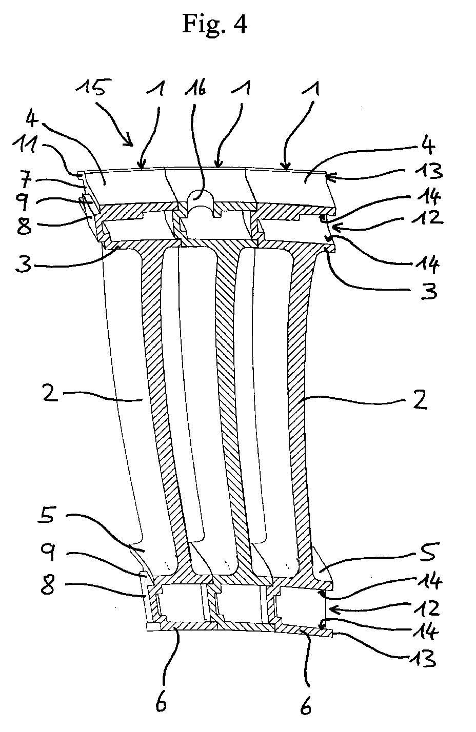
- FIG. 4 shows a guide vane segment 15 consisting of three guide vanes 1.
- Such guide vane segments from which a ring-shaped vane assembly is formed, serve for reinforcement of the individual guide vanes 1.
- the guide vanes 1 made of plastic become not only by the form fit between the projection 8 and the receptacle 12 adjacent Guide vanes 1 and the friction present in the contact surface are connected to one another, but additionally at least on the side surface 9 of the projection 8 or the inner surface 14 of the receptacle 12 glued together.
- the guide vanes 1 can also their first and second end faces 7 and 13 may be glued together.
- the adhesive connection between the side surface 9 of the projection 8 and the inner surface 14 of the receptacle 12 stressed under shear stresses during operation and is therefore clear more resilient than a bonded connection between the first and second end face 7 or 13.
- a plurality of guide vane segments 15 are used to form an annular guide ring assembly assembled, whereby these do not stick together to compensate for thermal expansion, but only by the positive connection between the projection 8 and the receptacle 12 are coupled to each other.
- the positive locking effect is caused by the between the side surface 9 of the projection 8 and the inner surface 14 of the receptacle 12 friction occurring Damping effect and thus an improvement in the dynamic vibration behavior of the Guide vane 1.
- the above-described limitation occurs due to the positive locking the vibration amplitude and sealing the gaps between adjacent vane segments.
- each guide vane 1 of a guide vane segment 15 is in the stiffening wall 4 outer platform 3, a hole provided a hole 16 is provided, in which a (not shown) engages bolts on the housing and the guide vane against gas / flow forces is supported in the circumferential direction.
- the stiffening wall 4 locally thickened around the bore 16 to reduce the surface pressure.
- the hole 16 is designed in the axial direction of the engine arrangement as an elongated hole, so that the gas or Flow forces in the axial direction via the rear, hook-like fastening means in the illustration 11 and not through the bolt into the engine housing.
- FIG. 5 shows the guide vane segment 15 from FIG. 4 in a perspective view, in which the Profile of the blades 2 can be seen. It can also be seen that the Dimensioning of the projection 8 and the receptacle 12 are coordinated so that align the outer and inner platforms 3 and 5 when assembled.
- the left part of the 5 shows the projections 8 on the outer and inner platforms 3, 5, that in a receptacle 12 of a guide vane 1 of an adjacent guide vane segment 15 is positively received within a lead ring assembly, but is not glued.
Landscapes
- Engineering & Computer Science (AREA)
- Mechanical Engineering (AREA)
- General Engineering & Computer Science (AREA)
- Turbine Rotor Nozzle Sealing (AREA)
- Structures Of Non-Positive Displacement Pumps (AREA)
- Control Of Turbines (AREA)
Abstract
Die Erfindung betrifft eine Leitschaufel für eine Gasturbine, insbesondere eine Niederdruckturbine,
mit einem Schaufelblatt, das sich zwischen einer inneren Plattform und einer äußeren Plattform
erstreckt, wobei die äußere Plattform Befestigungsmittel zur Anbringung an einem Gehäuse
aufweist, und wobei wenigstens eine von der äußeren oder inneren Plattform an einer ersten
Stirnfläche einen Vorsprung mit vorstehender Seitenfläche aufweist und an einer zweiten, gegenüberliegenden
Stirnfläche eine Aufnahme zum formschlüssigen Aufnehmen eines Vorsprungs
einer benachbarten Leitschaufel aufweist, deren Dimensionierung so auf den Vorsprung
abgestimmt ist, daß die Plattformen benachbarter Leitschaufeln im montierten Zustand
fluchten, ein Leitschaufelsegment aus wenigsten drei Leitschaufeln sowie einen Leitkranzverbund.
Description
Die Erfindung betrifft eine Leitschaufel für eine Gasturbine, insbesondere eine Niederdruckturbine, mit einem Schaufelblatt, das sich zwischen einer inneren Plattform und einer äußeren Plattform erstreckt, wobei die äußere Plattform Befestigungsmittel zur Anbringung an einem Gehäuse aufweist, ein Leitschaufelsegment aus wenigstens drei Leitschaufeln sowie einen Leitkranzverbund.The invention relates to a guide vane for a gas turbine, in particular a low-pressure turbine, with an airfoil located between an inner platform and an outer platform extends, the outer platform fastening means for attachment to a housing has, a guide vane segment from at least three guide vanes and a vane assembly.
Leitschaufeln von Niederdruckturbinen bestehen aus Metall und werden in der Entwicklungsphase im allgemeinen zunächst zu Segmenten aus drei oder sechs Leitschaufeln zusammengelötet. Bei den Untersuchungen zur aerodynamischen Auslegung des Profils der Schaufelblätter werden wie bei einem realen Gasturbinentriebwerk mehrere Leitschaufelsegmente zu einem geschlossenen Leitkranzverbund zusammengesetzt, wobei die einzelnen Leitschaufelsegmente zum Ausgleich von Wärmedehnungen untereinander nicht starr miteinander verbunden sind. Die Leitschaufeln sind dabei an ihren äußeren Plattformen in einem (Triebwerks-)Gehäuse befestigt und an ihren inneren Plattformen durch Metallklammern od. dgl. lösbar miteinander verspannt. Durch das Verspannen an den inneren Plattformen soll das Schwingungsverhalten der Schaufelblätter verbessert werden. Die Verwendung der Verspannungsklammern als zusätzliche Bauteile hat den Nachteil einer aufwendigeren Montage und höherer Kosten.Guide vanes of low pressure turbines are made of metal and are in the development phase generally first soldered together into segments of three or six guide vanes. During the investigations into the aerodynamic design of the profile of the airfoils like in a real gas turbine engine, several guide vane segments become one closed vane assembly, with the individual vane segments not rigidly connected to each other to compensate for thermal expansion are. The guide vanes are on their outer platforms in a (engine) housing attached and releasably together on their inner platforms by metal clips or the like tense. The vibration behavior is due to the tension on the inner platforms the blades are improved. The use of the braces as an additional Components have the disadvantage of more complex assembly and higher costs.
Zur Kalibrierung von aerodynamischen Auslegungsverfahren und zur schnellen Ermittlung von
Versuchsdaten von Druck-, Geschwindigkeits-oder Strömungsfeldmessungen werden alternativ
Leitschaufeln aus meist kohlefaserverstärkten Kunststoffen eingesetzt und in sog. aerodynamischen
![]()
![]()
Problematisch ist dabei, die Geometrie der äußeren und inneren Plattform der Leitschaufeln aus Metall für jene aus Kunststoff zu übernehmen, da diese den Belastungen mit den hohen, realen Gaskräften nicht standhalten können. Das Verkleben von jeweils drei oder sechs Leitschaufeln zu einzelnen Leitschaufelsegmenten, aus denen der Leitkranzverbund gebildet wird, hat dieses Problem ebensowenig gelöst, wie das Verspannen der Leitschaufeln mittels Bolzen, die in den seitlichen Stirnflächen der äußeren und inneren Plattformen vorgesehen sind. Die Schwingungsamplituden waren zu groß und führten zu Brüchen der Leitschaufeln.The problem here is the geometry of the outer and inner platform of the guide vanes Metal to take over for those made of plastic, as these can withstand the high, real Unable to withstand gas forces. Gluing three or six guide vanes each to individual guide vane segments from which the guide ring assembly is formed Problem solved just as little as the tensioning of the guide vanes by means of bolts which are in the lateral end faces of the outer and inner platforms are provided. The vibration amplitudes were too large and caused the guide vanes to break.
Der Erfindung liegt die Aufgabe zugrunde, eine Leitschaufel der eingangs beschriebenen Gattung zu schaffen, die ein verbessertes dynamisches Schwingungsverhalten aufweist, die Schwingungsamplitude benachbarter Leitschaufeln begrenzt und fertigungstechnisch einfach und kostengünstig herzustellen ist.The invention has for its object a guide vane of the type described above to create, which has an improved dynamic vibration behavior, the Vibration amplitude of adjacent guide vanes is limited and easy to manufacture and is inexpensive to manufacture.
Die Lösung der Aufgabe ist erfindungsgemäß dadurch gekennzeichnet, daß wenigstens eine von der äußeren oder inneren Plattform an einer ersten seitlichen Stirnfläche einen Vorsprung mit vorstehender Seitenfläche aufweist und an einer zweiten, gegenüber liegenden, seitlichen Stirnfläche eine Aufnahme zum formschlüssigen Aufnehmen eines Vorsprungs einer benachbarten Leitschaufel aufweist, deren Dimensionierung so auf den Vorsprung abgestimmt ist, daß die inneren und äußeren Plattformen benachbarter Leitschaufeln im montierten Zustand fluchten.The solution to the problem is characterized in that at least one a protrusion from the outer or inner platform on a first side face has with the protruding side surface and on a second, opposite, lateral End face a receptacle for positively receiving a projection of an adjacent one Has guide vane, the dimensions of which are so matched to the projection that align the inner and outer platforms of adjacent guide vanes when assembled.
Der Vorteil besteht darin, daß z.B. aneinander angrenzende Leitschaufeln benachbarter Leitschaufelsegmente (aus z.B. drei miteinander verbundenen Leitschaufeln) in Axialrichtung formschlüssig miteinander gekoppelt sind und durch die Reibung an den Kontaktflächen ein Dämpfungseffekt entsteht. Zudem bewirken die Vorsprünge einen Abdichtung von zwischen den Plattformen auftretenden Spalten.The advantage is that e.g. Adjacent vanes of adjacent vane segments (e.g. from three interconnected guide vanes) with a positive fit in the axial direction are coupled together and a damping effect due to the friction on the contact surfaces arises. In addition, the projections seal between the Platforms occurring columns.
In einer bevorzugten Ausgestaltung verläuft die Seitenfläche des Vorsprungs rechtwinklig zur ersten, im allgemeinen in Radialrichtung verlaufenden Stirnfläche der äußeren oder inneren Plattform. Die Seitenfläche des Vorsprungs verläuft mithin in der durch die Gasströmung stark belasteten Umfangsrichtung und ermöglicht dort eine Dämpfung infolge von Reibung an den Kontaktflächen.In a preferred embodiment, the side surface of the projection is perpendicular to first, generally radial end face of the outer or inner Platform. The side surface of the protrusion therefore runs strongly through the gas flow loaded circumferential direction and allows damping due to friction on the Contact areas.
Bevorzugt steht die Seitenfläche des Vorsprungs wenigstens 3 mm über die erste Stirnfläche der äußeren oder inneren Plattform vor, so daß eine ausreichend große Reib- bzw. Kontaktfläche mit der Aufnahme einer benachbarten Leitschaufel vorliegt.The side surface of the protrusion is preferably at least 3 mm above the first end surface the outer or inner platform, so that a sufficiently large friction or contact surface with the inclusion of an adjacent guide vane.
Es ist vorteilhaft, daß der Vorsprung wenigstens 30% der (Querschnitts-)Fläche der ersten Stirnfläche ausmacht, damit die benachbarten Leitschaufeln nicht lediglich punktuell miteinander gekoppelt sind und eine zuverlässige Begrenzung der Schwingungsamplitude ermöglicht wird.It is advantageous that the protrusion is at least 30% of the (cross-sectional) area of the first End face, so that the adjacent guide vanes do not just point to one another are coupled and a reliable limitation of the vibration amplitude is made possible.
Weiterhin ist es bevorzugt, daß der Vorsprung mit Spiel in der Ausnahme der benachbarten Leitschaufel sitzt bzw. eingepaßt ist, so daß sich bspw. aneinander angrenzende Leitschaufeln benachbarter Leitschaufelsegmente infolge von Wärmedehnungen problemlos voneinander weg und aufeinander zu bewegen können.Furthermore, it is preferred that the projection with play in the exception of the neighboring one The guide vane sits or is fitted so that, for example, adjoining guide vanes Adjacent vane segments easily move away from each other due to thermal expansion and can move towards each other.
Höchst bevorzugt verläuft eine an die zweite Stirnfläche angrenzende Innenfläche der Aufnahme im montierten Zustand parallel zur Seitenfläche des Vorsprungs, so daß ein sicherer Reibkontakt zwischen der Innenfläche der Aufnahme und der Seitenfläche des Vorsprungs gewährleistet ist. Most preferably, an inner surface of the receptacle adjoining the second end surface runs in the assembled state parallel to the side surface of the projection, so that a secure friction contact guaranteed between the inner surface of the receptacle and the side surface of the projection is.
Es ist bevorzugt, daß die äußere Plattform eine Plattform und eine Versteifungswand umfaßt, die über mit Abstand zueinander verlaufende Querstreben verbunden sind und/oder die innere Plattform eine Plattform und eine Verstärkungswand umfaßt. Hierdurch wird die Torsions- und Biegesteifigkeit der inneren Plattform und insbesondere der aus der Plattform, der Versteifungswand sowie den beiden Querstreben bestehenden äußeren Plattform, die zudem mit dem Befestigungsmittel zur Anbringung der Leitschaufel an dem Triebwerksgehäuse versehen ist, deutlich erhöht. Durch diese geometrische Maßnahme hält die Leitschaufel auch beim Einsatz vergleichsweise schwächerer Werkstoffe, wie z.B. faserverstärkter Kunststoff, den verhältnismäßig hohen realen Gaskräften Stand.It is preferred that the outer platform include a platform and a stiffening wall which are connected by cross struts running at a distance from one another and / or the inner one Platform includes a platform and a reinforcement wall. This will make the torsion and Flexural rigidity of the inner platform and in particular that of the platform, the stiffening wall as well as the two cross struts existing outer platform, which also with the Fastening means for attaching the guide blade to the engine housing is provided, clearly increased. Thanks to this geometric measure, the guide vane also lasts when in use comparatively weaker materials, e.g. fiber-reinforced plastic, the proportionately high real gas forces.
In einer bevorzugten Ausgestaltung ist die Leitschaufel einstückig ausgebildet, so daß sie kostengünstig durch Metall- oder Spritzgußverfahren hergestellt werden kann.In a preferred embodiment, the guide vane is formed in one piece, so that it is inexpensive can be made by metal or injection molding.
Höchst bevorzugt besteht die Leitschaufel aus kohlefaserverstärktem Kunststoff, so daß sie sich
in sog. aerodynamischen
Weitere Ausgestaltungen der Erfindung sind in den Unteransprüchen beschrieben.Further refinements of the invention are described in the subclaims.
Im folgenden wird die Erfindung anhand eines Ausführungsbeispiels unter Bezugnahme auf eine Zeichnung näher erläutert. Es zeigt:
- Fig. 1
- einen Längsschnitt in perspektivischer Darstellung eines Ausführungsbeispiels der erfindungsgemäßen Leitschaufel,
- Fig. 2
- eine Seitenansicht der Leitschaufel aus Fig. 1,
- Fig. 3
- eine Seitenansicht der schwingenden Leitschaufel aus Fig. 1 und 2,
- Fig. 4
- einen Längsschnitt in perspektivischer Darstellung eines Leitschaufelsegments aus drei Leitschaufeln gemäß Fig. 1 bis 3 und
- Fig. 5
- eine perspektivische Darstellung des Leitschaufelsegments aus Fig. 4.
- Fig. 1
- 2 shows a longitudinal section in perspective representation of an exemplary embodiment of the guide vane according to the invention,
- Fig. 2
- 2 shows a side view of the guide vane from FIG. 1,
- Fig. 3
- 2 shows a side view of the vibrating guide vane from FIGS. 1 and 2,
- Fig. 4
- a longitudinal section in a perspective view of a guide vane segment from three guide vanes according to FIGS. 1 to 3 and
- Fig. 5
- 3 shows a perspective illustration of the guide vane segment from FIG. 4.
Fig. 1 zeigt ein im ganzen mit 1 bezeichnetes Ausführungsbeispiel der erfindungsgemäßen Leitschaufel,
die aus kohlefaserverstärkten Kunststoff besteht und im Spritzgußverfahren hergestellt
ist. Eine solche Leitschaufel 1 wird in sog. aerodynamischen
Die Leitschaufel 1 umfaßt ein Schaufelblatt 2, eine äußere Plattform 3 aus einer Plattform 3' und
einer mit Abstand dazu angeordneten Versteifungswand 4 sowie eine innere Plattform 5 aus einer
Plattform 5' und einer damit verbundenen und sich ebenfalls mit Abstand dazu erstreckenden
Verstärkungswand 6. Sowohl die äußere als auch die innere Plattform 3 bzw. 5 ist an einer
ersten Stirnfläche 7 mit einem Vorsprung 8 versehen, der jeweils eine über die erste Stirnfläche
7 um etwa 3 mm vorstehende Seitenfläche 9 aufweist.The
Wenn mehrere Leitschaufeln 1 zu einem ringförmigen Leitkranzverbund zusammengesetzt und
in einem Triebwerksgehäuse befestigt sind, ist das Schaufelblatt 2 mit seiner zwischen der äußeren
und inneren Plattform 3 bzw. 5 iverlaufenden Längserstreckung m wesentlichen in Radialrichtung
der Triebwerksanordnung angeordnet.If
Fig. 2 zeigt die Leitschaufel 1 aus Fig. 1 in einer Seitenansicht, in der die im wesentlichen parallel
zur (äußeren) Plattform 3' verlaufende Versteifungswand 4 sowie mit der (inneren) Plattform
5' verbundene, sich über mehrere Ecken erstreckende Verstärkungswand 6 dargestellt
sind. An der äußeren Plattform 3 sind zwei hakenartige Befestigungsmittel 10 zur Anbringung
der Leitschaufel 1 an einem (nicht gezeigten) Triebwerksgehäuse ausgebildet. Der zwischen der
(äußeren) Plattform 3', der Versteifungswand 4 und sich dazwischen erstreckenden Querstreben
10 einerseits sowie der (inneren) Plattform 5' und der Verstärungswand 6 andererseits vorliegende
Hohlraum bildet jeweils eine Aufnahme 12, mit der die zweite Stirnfläche 13 der äußeren
und inneren Plattform 3 bzw. 5 versehen ist.Fig. 2 shows the
Wenn mehrere Leitschaufeln 1 zu einem Leitkranzverbund zusammengesetzt werden, wird ein
Vorsprung 8 einer benachbarten Leitschaufel 1 in dieser Aufnahme 12 formschlüssig aufgenommen,
wobei deren Dimensionierung auf jene des Vorsprungs 8 so abgestimmt ist, daß die
äußeren und innerne Plattformen 3 bzw. 5 benachbarter Leitschaufeln 1 im montierten Zustand
fluchten, wie dieses in Fig. 4 und 5 zu erkennen ist. Die Aufnahme 12 besitzt eine an die zweite
Stirnfläche 13 angrenzende Innenfläche 14, die im montierten Zustand aufgrund der abgestimmten
Dimensionierung des Vorsprungs 8 und der Aufnahme 12 eine Kontaktfläche mit der
Seitenfläche 9 des Vorsprungs 8 bildet. Auf diese Weise wird zudem eine Abdichtung zwischen
benachbarten Leitschaufeln 1 erzielt. In Fig. 2 ist zu erkennen, daß der Vorsprung 8 und die
Aufnahme 12 mehr als 50 % der in der Bildebene liegenden Querschnittsfläche der ersten bzw.
zweiten Stirnfläche 7 bzw. 13 ausmachen.If
Fig. 3 zeigt eine einzelne, in Axialrichtung schwingende Leitschaufel 1, wobei zwei unterschiedliche
Schwingungszustände dargestellt sind. Die in Fig. 3 insbesondere an der inneren Plattform
5 bzw. deren der Verstärkungswand 6 deutlich zu erkennende Schwingungsamplitude wird bei
der in einem Leitkranzverbund angeordneten, erfindungsgemäßen Leitschaufel 1 dadurch wirksam
begrenzt, daß jeweils der Vorsprung 8 in der Aufnahme 12 einer benachbarten Leitschaufel
1 formschlüssig aufgenommen ist. Zudem erfolgt eine Dämpfung der Schwingung durch die
zwischen den Innenflächen 14 der Aufnahme 12 und der Seitenfläche 9 des Vorsprungs 8 auftretende
Reibung.3 shows a
Fig. 4 zeigt ein aus drei Leitschaufeln 1 bestehendes Leitschaufelsegment 15. Derartige Leitschaufelsegmente,
aus denen ein ringförmiger Leitkranzverbund gebildet wird, dienen zur Verstärkung
der einzelnen Leitschaufeln 1. Die aus Kunststoff bestehenden Leitschaufeln 1 werden
nicht nur durch den Formschluß zwischen dem Vorsprung 8 und der Aufnahme 12 benachbarter
Leitschaufeln 1 sowie die in der Kontaktfläche vorliegende Reibung miteinander verbunden,
sondern zusätzlich wenigstens an der Seitenfläche 9 des Vorsprungs 8 bzw. der Innenfläche
14 der Aufnahme 12 miteinander verklebt. Zusätzlich können die Leitschaufeln 1 auch an
ihren ersten und zweiten Stirnflächen 7 bzw. 13 miteinander verklebt sein. Die Klebverbindung
zwischen der Seitenfläche 9 des Vorsprungs 8 und der Innenfläche 14 der Aufnahme 12 wird
unter den im Betrieb auftretenden Belastungen auf Scherung beansprucht und ist somit deutlich
höher belastbar als eine auf Zug/Druck beanspruchte Klebverbindung zwischen der ersten und
zweiten Stirnfläche 7 bzw. 13.4 shows a
Zur Bildung eines ringförmigen Leitkranzverbunds werden mehrere Leitschaufelsegmente 15
zusammengesetzt, wobei diese zum Ausgleich von Wärmedehnungen nicht miteinander verklebt,
sondern lediglich durch den Fomschluß zwischen dem Vorsprung 8 und der Aufnahme 12
aneinander gekoppelt sind. Der Formschluß bewirkt jedoch durch die zwischen der Seitenfläche
9 des Vorsprungs 8 und der Innenfläche 14 der Aufnahme 12 auftretende Reibung einen
Dämpfungseffekt und somit eine Verbesserung des dynamischen Schwingungsverhaltens der
Leitschaufel 1. Darüber hinaus erfolgt durch den Formschluß die oben beschriebene Begrenzung
der Schwingungsamplitude und eine Abdichtung der Spalten zwischen benachbarten Leitschaufelsegmenten.A plurality of
In jeweils einer Leitschaufel 1 eines Leitschaufelsegments 15 ist in der Versteifungswand 4 der
äußeren Plattform 3 eine Bohrung vorgesehen eine Bohrung 16 vorgesehen, in die ein (nicht
dargestellter) gehäuseseitiger Bolzen eingreift und die Leitschaufel gegen Gas-/Strömungskräfte
in Umfangsrichtung abstützt. Wie in Fig. 4 gezeigt, ist die Versteifungswand 4
um die Bohrung 16 herum zur Reduzierung der Flächenpressung örtlich verdickt. Die Bohrung
16 ist in Axialrichtung der Triebwerksanordnung als Langloch ausgebildet, so daß die Gas- bzw.
Strömungskräfte in Axialrichtung über den in der Darstellung hinteren, hakenartigen Befestigungsmittel
11 und nicht über den Bolzen in das Triebwerksgehäuse geleitet werden.In each
Fig. 5 zeigt das Leitschaufelsegment 15 aus Fig. 4 in perspektivischer Darstellung, in der das
Profil der Schaufelblätter 2 andeutungsweise zu erkennen ist. Es ist ferner zu erkennen, daß die
Dimensionierung des Vorsprungs 8 und der Aufnahme 12 so aufeinander abgestimmt sind, daß
die äußere und innere Plattform 3 bzw. 5 im montierten Zustand fluchten. Im linken Teil der
Zeichnung gemäß Fig. 5 sind die Vorsprünge 8 ander äußeren und inneren Plattform 3,5 dargestellt,
die in einer Aufnahme 12 einer Leitschaufel 1 eines benachbarten Leitschaufelsegments
15 innerhalb eines Leitkranzverbundes formschlüssig aufgenommen, jedoch nicht verklebt wird.FIG. 5 shows the
Claims (19)
Applications Claiming Priority (2)
| Application Number | Priority Date | Filing Date | Title |
|---|---|---|---|
| DE29715180U | 1997-08-23 | ||
| DE29715180U DE29715180U1 (en) | 1997-08-23 | 1997-08-23 | Guide blade for a gas turbine |
Publications (3)
| Publication Number | Publication Date |
|---|---|
| EP0899426A2 true EP0899426A2 (en) | 1999-03-03 |
| EP0899426A3 EP0899426A3 (en) | 1999-12-08 |
| EP0899426B1 EP0899426B1 (en) | 2003-04-02 |
Family
ID=8045040
Family Applications (1)
| Application Number | Title | Priority Date | Filing Date |
|---|---|---|---|
| EP98114445A Expired - Lifetime EP0899426B1 (en) | 1997-08-23 | 1998-08-01 | Guide vane for a gas turbine |
Country Status (4)
| Country | Link |
|---|---|
| US (1) | US6217282B1 (en) |
| EP (1) | EP0899426B1 (en) |
| JP (1) | JPH11107704A (en) |
| DE (2) | DE29715180U1 (en) |
Cited By (7)
| Publication number | Priority date | Publication date | Assignee | Title |
|---|---|---|---|---|
| EP1219783A3 (en) * | 2000-12-28 | 2004-02-11 | ALSTOM (Switzerland) Ltd | Stator vane for an axial flow turbine |
| EP2295724A1 (en) * | 2009-08-28 | 2011-03-16 | Siemens Aktiengesellschaft | Stator vane for an axial-flow turbomachine and corresponding stator vane assembly |
| WO2012041651A1 (en) * | 2010-09-30 | 2012-04-05 | Siemens Aktiengesellschaft | Blade ring segment, turbomachine and method for producing same |
| EP2617945A1 (en) * | 2012-01-23 | 2013-07-24 | MTU Aero Engines GmbH | Rotor for a turbo machine |
| ITCO20130004A1 (en) * | 2013-02-20 | 2014-08-21 | Nuovo Pignone Srl | METHOD TO REALIZE A IMPELLER FROM SECTOR SEGMENTS |
| EP3339608A3 (en) * | 2012-08-27 | 2018-09-05 | United Technologies Corporation | Shiplap cantilevered stator |
| WO2023247857A1 (en) * | 2022-06-22 | 2023-12-28 | Safran Aircraft Engines | Turbomachine blading assembly comprising means for limiting vibration between platforms |
Families Citing this family (39)
| Publication number | Priority date | Publication date | Assignee | Title |
|---|---|---|---|---|
| US6435813B1 (en) * | 2000-05-10 | 2002-08-20 | General Electric Company | Impigement cooled airfoil |
| DE10111896B8 (en) * | 2001-03-13 | 2012-06-06 | Eads Space Transportation Gmbh | Metallic ring for the connection of two rotationally symmetrical structural parts |
| JP4481822B2 (en) * | 2002-08-14 | 2010-06-16 | ボルボ エアロ コーポレイション | Manufacturing method of stator blade component |
| US7597542B2 (en) * | 2005-08-30 | 2009-10-06 | General Electric Company | Methods and apparatus for controlling contact within stator assemblies |
| US7594404B2 (en) * | 2006-07-27 | 2009-09-29 | United Technologies Corporation | Embedded mount for mid-turbine frame |
| US8257038B2 (en) * | 2008-02-01 | 2012-09-04 | Siemens Energy, Inc. | Metal injection joining |
| US8043044B2 (en) * | 2008-09-11 | 2011-10-25 | General Electric Company | Load pin for compressor square base stator and method of use |
| US20100068050A1 (en) * | 2008-09-12 | 2010-03-18 | General Electric Company | Gas turbine vane attachment |
| US8356975B2 (en) * | 2010-03-23 | 2013-01-22 | United Technologies Corporation | Gas turbine engine with non-axisymmetric surface contoured vane platform |
| US8360716B2 (en) * | 2010-03-23 | 2013-01-29 | United Technologies Corporation | Nozzle segment with reduced weight flange |
| US9976433B2 (en) | 2010-04-02 | 2018-05-22 | United Technologies Corporation | Gas turbine engine with non-axisymmetric surface contoured rotor blade platform |
| FR2961554B1 (en) * | 2010-06-18 | 2012-07-20 | Snecma | ANGULAR RECTIFIER SECTOR FOR TURBOMACHINE COMPRESSOR, TURBOMACHINE RECTIFIER AND TURBOMACHINE COMPRISING SUCH A SECTOR |
| JP5358559B2 (en) * | 2010-12-28 | 2013-12-04 | 株式会社日立製作所 | Axial flow compressor |
| US9028744B2 (en) | 2011-08-31 | 2015-05-12 | Pratt & Whitney Canada Corp. | Manufacturing of turbine shroud segment with internal cooling passages |
| US8784041B2 (en) | 2011-08-31 | 2014-07-22 | Pratt & Whitney Canada Corp. | Turbine shroud segment with integrated seal |
| US9079245B2 (en) | 2011-08-31 | 2015-07-14 | Pratt & Whitney Canada Corp. | Turbine shroud segment with inter-segment overlap |
| US8784044B2 (en) | 2011-08-31 | 2014-07-22 | Pratt & Whitney Canada Corp. | Turbine shroud segment |
| US8784037B2 (en) | 2011-08-31 | 2014-07-22 | Pratt & Whitney Canada Corp. | Turbine shroud segment with integrated impingement plate |
| EP2666969B1 (en) * | 2012-05-21 | 2017-04-19 | General Electric Technology GmbH | Turbine diaphragm construction |
| EP2669477B1 (en) * | 2012-05-31 | 2017-04-05 | General Electric Technology GmbH | Shroud for airfoils |
| US9556746B2 (en) | 2013-10-08 | 2017-01-31 | Pratt & Whitney Canada Corp. | Integrated strut and turbine vane nozzle arrangement |
| US9816387B2 (en) | 2014-09-09 | 2017-11-14 | United Technologies Corporation | Attachment faces for clamped turbine stator of a gas turbine engine |
| US10018075B2 (en) * | 2015-04-22 | 2018-07-10 | General Electric Company | Methods for positioning neighboring nozzles of a gas turbine engine |
| JP6763157B2 (en) * | 2016-03-11 | 2020-09-30 | 株式会社Ihi | Turbine nozzle |
| WO2017158637A1 (en) * | 2016-03-15 | 2017-09-21 | 株式会社 東芝 | Turbine and turbine stator blade |
| GB2551164B (en) * | 2016-06-08 | 2019-12-25 | Rolls Royce Plc | Metallic stator vane |
| US10533454B2 (en) | 2017-12-13 | 2020-01-14 | Pratt & Whitney Canada Corp. | Turbine shroud cooling |
| US10570773B2 (en) | 2017-12-13 | 2020-02-25 | Pratt & Whitney Canada Corp. | Turbine shroud cooling |
| US11274569B2 (en) | 2017-12-13 | 2022-03-15 | Pratt & Whitney Canada Corp. | Turbine shroud cooling |
| US10502093B2 (en) * | 2017-12-13 | 2019-12-10 | Pratt & Whitney Canada Corp. | Turbine shroud cooling |
| US10738634B2 (en) * | 2018-07-19 | 2020-08-11 | Raytheon Technologies Corporation | Contact coupled singlets |
| JP2021143658A (en) * | 2020-03-13 | 2021-09-24 | 東芝エネルギーシステムズ株式会社 | Turbine stationary blade |
| US11365645B2 (en) | 2020-10-07 | 2022-06-21 | Pratt & Whitney Canada Corp. | Turbine shroud cooling |
| EP4105449A1 (en) | 2021-06-18 | 2022-12-21 | Raytheon Technologies Corporation | Hybrid bonded configuration for blade outer airseal (boas) |
| EP4105438B1 (en) | 2021-06-18 | 2026-04-08 | RTX Corporation | Bonding method for the repair of a gas turbine engine part |
| US12055056B2 (en) | 2021-06-18 | 2024-08-06 | Rtx Corporation | Hybrid superalloy article and method of manufacture thereof |
| EP4105444A1 (en) * | 2021-06-18 | 2022-12-21 | Raytheon Technologies Corporation | Joining individual turbine vanes with field assisted sintering technology (fast) |
| EP4105450A1 (en) | 2021-06-18 | 2022-12-21 | Raytheon Technologies Corporation | Passive clearance control (apcc) system produced by field assisted sintering technology (fast) |
| DE102024104404A1 (en) * | 2024-02-16 | 2025-08-21 | MTU Aero Engines AG | Guide vane segment |
Family Cites Families (8)
| Publication number | Priority date | Publication date | Assignee | Title |
|---|---|---|---|---|
| DE485833C (en) * | 1929-11-08 | J A Maffei A G | Process for the production of blades for turbo machines, in particular for steam or gas turbines | |
| GB723505A (en) * | 1952-11-18 | 1955-02-09 | Parsons & Marine Eng Turbine | Improvements in or relating to turbine nozzles |
| GB918692A (en) * | 1958-07-11 | 1963-02-13 | Ass Elect Ind | Improvements relating to turbine nozzle blocks |
| US3442442A (en) * | 1966-12-02 | 1969-05-06 | Gen Electric | Mounting of blades in an axial flow compressor |
| CH488928A (en) * | 1968-03-22 | 1970-04-15 | Sulzer Ag | Guide vane fastening in turbo machines |
| US4832568A (en) * | 1982-02-26 | 1989-05-23 | General Electric Company | Turbomachine airfoil mounting assembly |
| JP3631271B2 (en) * | 1993-11-19 | 2005-03-23 | ユナイテッド テクノロジーズ コーポレイション | Inner shroud integrated stator vane structure |
| US5848874A (en) * | 1997-05-13 | 1998-12-15 | United Technologies Corporation | Gas turbine stator vane assembly |
-
1997
- 1997-08-23 DE DE29715180U patent/DE29715180U1/en not_active Expired - Lifetime
-
1998
- 1998-08-01 EP EP98114445A patent/EP0899426B1/en not_active Expired - Lifetime
- 1998-08-01 DE DE59807705T patent/DE59807705D1/en not_active Expired - Fee Related
- 1998-08-06 JP JP10223253A patent/JPH11107704A/en active Pending
- 1998-08-24 US US09/138,983 patent/US6217282B1/en not_active Expired - Fee Related
Cited By (19)
| Publication number | Priority date | Publication date | Assignee | Title |
|---|---|---|---|---|
| EP1219783A3 (en) * | 2000-12-28 | 2004-02-11 | ALSTOM (Switzerland) Ltd | Stator vane for an axial flow turbine |
| EP2295724A1 (en) * | 2009-08-28 | 2011-03-16 | Siemens Aktiengesellschaft | Stator vane for an axial-flow turbomachine and corresponding stator vane assembly |
| CN102003219A (en) * | 2009-08-28 | 2011-04-06 | 西门子公司 | Stator vane for an axial-flow turbomachine and corresponding stator vane assembly |
| CN102003219B (en) * | 2009-08-28 | 2013-12-18 | 西门子公司 | Stator vane for axial-flow turbomachine and corresponding stator vane assembly |
| US8622708B2 (en) | 2009-08-28 | 2014-01-07 | Siemens Aktiengesellschaft | Stator blade for a turbomachine which is exposable to axial throughflow, and also stator blade arrangement for it |
| WO2012041651A1 (en) * | 2010-09-30 | 2012-04-05 | Siemens Aktiengesellschaft | Blade ring segment, turbomachine and method for producing same |
| CN103119249A (en) * | 2010-09-30 | 2013-05-22 | 西门子公司 | Blade ring segment, turbomachine and method for producing same |
| US9657581B2 (en) | 2012-01-23 | 2017-05-23 | Mtu Aero Engines Gmbh | Rotor for a turbomachine |
| EP2617945A1 (en) * | 2012-01-23 | 2013-07-24 | MTU Aero Engines GmbH | Rotor for a turbo machine |
| US10309235B2 (en) | 2012-08-27 | 2019-06-04 | United Technologies Corporation | Shiplap cantilevered stator |
| EP3339608A3 (en) * | 2012-08-27 | 2018-09-05 | United Technologies Corporation | Shiplap cantilevered stator |
| ITCO20130004A1 (en) * | 2013-02-20 | 2014-08-21 | Nuovo Pignone Srl | METHOD TO REALIZE A IMPELLER FROM SECTOR SEGMENTS |
| US9945388B2 (en) | 2013-02-20 | 2018-04-17 | Nuovo Pignone Srl | Method for making an impeller from sector segments |
| RU2661690C2 (en) * | 2013-02-20 | 2018-07-19 | Нуово Пиньоне СРЛ | Method for manufacturing an impeller from sector segments |
| CN105209208A (en) * | 2013-02-20 | 2015-12-30 | 诺沃皮尼奥内股份有限公司 | Method for manufacturing impellers from sector segments |
| WO2014128169A1 (en) * | 2013-02-20 | 2014-08-28 | Nuovo Pignone Srl | Method for making an impeller from sector segments |
| WO2023247857A1 (en) * | 2022-06-22 | 2023-12-28 | Safran Aircraft Engines | Turbomachine blading assembly comprising means for limiting vibration between platforms |
| FR3137120A1 (en) * | 2022-06-22 | 2023-12-29 | Safran Aircraft Engines | Bladed turbomachine assembly comprising means of limiting vibrations between platforms |
| US12486775B1 (en) | 2022-06-22 | 2025-12-02 | Safran Aircraft Engines | Turbomachine blading assembly comprising means for limiting vibration between platforms |
Also Published As
| Publication number | Publication date |
|---|---|
| EP0899426B1 (en) | 2003-04-02 |
| DE59807705D1 (en) | 2003-05-08 |
| EP0899426A3 (en) | 1999-12-08 |
| US6217282B1 (en) | 2001-04-17 |
| DE29715180U1 (en) | 1997-10-16 |
| JPH11107704A (en) | 1999-04-20 |
Similar Documents
| Publication | Publication Date | Title |
|---|---|---|
| EP0899426A2 (en) | Guide vane for a gas turbine | |
| DE3911691C2 (en) | Composite fastening element and thus formed composite fastening | |
| DE10210866C1 (en) | Guide blade segment fixing device for flow channel of aircraft gas turbine uses slot and hook fixing and pin fitting through latter | |
| DE60023979T2 (en) | fan platform | |
| EP3199758B1 (en) | Rotor in blisk or bling structure of an aircraft engine | |
| DE60222324T2 (en) | Mounting of metallic attachments on CMC turbomachinery combustion chamber walls | |
| DE2339468A1 (en) | SHOVEL CONSTRUCTION FOR MACHINERY THROUGH FLOWING MEANS | |
| DE2841793A1 (en) | SHOVEL DAMPER | |
| EP1450006A1 (en) | Compressor blade for aircraft engines | |
| DE10324166B4 (en) | Rotor blade connection | |
| EP2484870A1 (en) | Blade of a turbomachine with damping element and method of designing a turbomachine | |
| DE3305880A1 (en) | FASTENING ARRANGEMENT FOR TURBINE BLADES | |
| DE4108085A1 (en) | BLADE FOR A GAS TURBINE ENGINE | |
| DE102005001864B3 (en) | Turbine housing for exhaust gas supercharger has spacing elements with recesses enabling direct application of exhaust gas flow to holding elements | |
| DE19828817A1 (en) | Turbine rotor with releasably connected blade disks | |
| EP1462610A1 (en) | Rotor blade row for turbomachines | |
| EP1676980A1 (en) | Turbocharger with variable geometry turbine and manufacturing method | |
| DE102011050961A1 (en) | Turbine blade arrangement | |
| DE102015203868A1 (en) | Fan blade for a propulsion system | |
| DE2927654A1 (en) | CANTILEVER STRUCTURE, ESPECIALLY FOR DECK TAPE SECTIONS OF A BLADED ROTOR FROM GAS TURBINE ENGINES | |
| DE2645174A1 (en) | ROTOR HEAD FOR AN IMPACT AND SWIVEL-LESS ROTOR | |
| DE602004008950T2 (en) | STIFFING A HOLLOW TURBINE BLADE | |
| DE102008060705A1 (en) | Horizontally split turbomachine housing | |
| DE1911484A1 (en) | Process for the manufacture of stator blades for gas turbine engines | |
| DE60307302T2 (en) | Fastening device for stator blade, and Leitschaufelstufe a compressor with such a device |
Legal Events
| Date | Code | Title | Description |
|---|---|---|---|
| PUAI | Public reference made under article 153(3) epc to a published international application that has entered the european phase |
Free format text: ORIGINAL CODE: 0009012 |
|
| AK | Designated contracting states |
Kind code of ref document: A2 Designated state(s): CH DE ES FR GB IT LI SE |
|
| AX | Request for extension of the european patent |
Free format text: AL;LT;LV;MK;RO;SI |
|
| PUAL | Search report despatched |
Free format text: ORIGINAL CODE: 0009013 |
|
| AK | Designated contracting states |
Kind code of ref document: A3 Designated state(s): AT BE CH CY DE DK ES FI FR GB GR IE IT LI LU MC NL PT SE |
|
| AX | Request for extension of the european patent |
Free format text: AL;LT;LV;MK;RO;SI |
|
| RIC1 | Information provided on ipc code assigned before grant |
Free format text: 6F 01D 9/04 A, 6F 01D 5/22 B |
|
| 17P | Request for examination filed |
Effective date: 19991214 |
|
| AKX | Designation fees paid |
Free format text: CH DE ES FR GB IT LI SE |
|
| RAP1 | Party data changed (applicant data changed or rights of an application transferred) |
Owner name: MTU AERO ENGINES GMBH |
|
| 17Q | First examination report despatched |
Effective date: 20020305 |
|
| GRAH | Despatch of communication of intention to grant a patent |
Free format text: ORIGINAL CODE: EPIDOS IGRA |
|
| GRAH | Despatch of communication of intention to grant a patent |
Free format text: ORIGINAL CODE: EPIDOS IGRA |
|
| GRAA | (expected) grant |
Free format text: ORIGINAL CODE: 0009210 |
|
| AK | Designated contracting states |
Designated state(s): CH DE ES FR GB IT LI SE |
|
| PG25 | Lapsed in a contracting state [announced via postgrant information from national office to epo] |
Ref country code: IT Free format text: LAPSE BECAUSE OF FAILURE TO SUBMIT A TRANSLATION OF THE DESCRIPTION OR TO PAY THE FEE WITHIN THE PRESCRIBED TIME-LIMIT;WARNING: LAPSES OF ITALIAN PATENTS WITH EFFECTIVE DATE BEFORE 2007 MAY HAVE OCCURRED AT ANY TIME BEFORE 2007. THE CORRECT EFFECTIVE DATE MAY BE DIFFERENT FROM THE ONE RECORDED. Effective date: 20030402 |
|
| REG | Reference to a national code |
Ref country code: GB Ref legal event code: FG4D Free format text: NOT ENGLISH |
|
| REG | Reference to a national code |
Ref country code: CH Ref legal event code: EP |
|
| REF | Corresponds to: |
Ref document number: 59807705 Country of ref document: DE Date of ref document: 20030508 Kind code of ref document: P |
|
| GBT | Gb: translation of ep patent filed (gb section 77(6)(a)/1977) | ||
| PG25 | Lapsed in a contracting state [announced via postgrant information from national office to epo] |
Ref country code: SE Free format text: LAPSE BECAUSE OF FAILURE TO SUBMIT A TRANSLATION OF THE DESCRIPTION OR TO PAY THE FEE WITHIN THE PRESCRIBED TIME-LIMIT Effective date: 20030702 |
|
| PG25 | Lapsed in a contracting state [announced via postgrant information from national office to epo] |
Ref country code: LI Free format text: LAPSE BECAUSE OF NON-PAYMENT OF DUE FEES Effective date: 20030831 Ref country code: CH Free format text: LAPSE BECAUSE OF NON-PAYMENT OF DUE FEES Effective date: 20030831 |
|
| PG25 | Lapsed in a contracting state [announced via postgrant information from national office to epo] |
Ref country code: ES Free format text: LAPSE BECAUSE OF FAILURE TO SUBMIT A TRANSLATION OF THE DESCRIPTION OR TO PAY THE FEE WITHIN THE PRESCRIBED TIME-LIMIT Effective date: 20031030 |
|
| ET | Fr: translation filed | ||
| PLBE | No opposition filed within time limit |
Free format text: ORIGINAL CODE: 0009261 |
|
| STAA | Information on the status of an ep patent application or granted ep patent |
Free format text: STATUS: NO OPPOSITION FILED WITHIN TIME LIMIT |
|
| 26N | No opposition filed |
Effective date: 20040105 |
|
| REG | Reference to a national code |
Ref country code: CH Ref legal event code: PL |
|
| PGFP | Annual fee paid to national office [announced via postgrant information from national office to epo] |
Ref country code: DE Payment date: 20060816 Year of fee payment: 9 |
|
| PGFP | Annual fee paid to national office [announced via postgrant information from national office to epo] |
Ref country code: FR Payment date: 20060817 Year of fee payment: 9 |
|
| PGFP | Annual fee paid to national office [announced via postgrant information from national office to epo] |
Ref country code: GB Payment date: 20060824 Year of fee payment: 9 |
|
| GBPC | Gb: european patent ceased through non-payment of renewal fee |
Effective date: 20070801 |
|
| REG | Reference to a national code |
Ref country code: FR Ref legal event code: ST Effective date: 20080430 |
|
| PG25 | Lapsed in a contracting state [announced via postgrant information from national office to epo] |
Ref country code: DE Free format text: LAPSE BECAUSE OF NON-PAYMENT OF DUE FEES Effective date: 20080301 |
|
| PG25 | Lapsed in a contracting state [announced via postgrant information from national office to epo] |
Ref country code: FR Free format text: LAPSE BECAUSE OF NON-PAYMENT OF DUE FEES Effective date: 20070831 |
|
| PG25 | Lapsed in a contracting state [announced via postgrant information from national office to epo] |
Ref country code: GB Free format text: LAPSE BECAUSE OF NON-PAYMENT OF DUE FEES Effective date: 20070801 |