EP0899191B1 - Aircraft nose landing gear - Google Patents
Aircraft nose landing gear Download PDFInfo
- Publication number
- EP0899191B1 EP0899191B1 EP98202425A EP98202425A EP0899191B1 EP 0899191 B1 EP0899191 B1 EP 0899191B1 EP 98202425 A EP98202425 A EP 98202425A EP 98202425 A EP98202425 A EP 98202425A EP 0899191 B1 EP0899191 B1 EP 0899191B1
- Authority
- EP
- European Patent Office
- Prior art keywords
- landing gear
- wheel well
- nose
- nose wheel
- outboard
- Prior art date
- Legal status (The legal status is an assumption and is not a legal conclusion. Google has not performed a legal analysis and makes no representation as to the accuracy of the status listed.)
- Expired - Lifetime
Links
Images


Classifications
-
- B—PERFORMING OPERATIONS; TRANSPORTING
- B64—AIRCRAFT; AVIATION; COSMONAUTICS
- B64C—AEROPLANES; HELICOPTERS
- B64C25/00—Alighting gear
-
- B—PERFORMING OPERATIONS; TRANSPORTING
- B64—AIRCRAFT; AVIATION; COSMONAUTICS
- B64C—AEROPLANES; HELICOPTERS
- B64C25/00—Alighting gear
- B64C25/02—Undercarriages
- B64C25/08—Undercarriages non-fixed, e.g. jettisonable
- B64C25/10—Undercarriages non-fixed, e.g. jettisonable retractable, foldable, or the like
Definitions
- the present invention relates to a nose gear installation and more particularly to a means for securing an aircraft nose landing gear assembly into the nose wheel well support structure of an aircraft. Specifically, the invention relates to an aircraft nose landing gear system as defined in the pre-characterizing part of claim 1.
- EP-A-0 597 688 discloses a trolley for transporting and positioning a landing gear prior to installation on an aircraft.
- a landing gear is positioned in the wheel well such as to align the fittings or bearings on the landing gear with corresponding bearings in the wheel well structure, after which a trunnion pin or pintle pin is inserted into the bearings. It is summarily stated that the bearings are then secured, without any indication of how this is achieved.
- US-A-5,337,976 schematically shows a landing gear pivotally mounted to an aircraft structure by means of a pin received in an opening in the structure. There is no indication of any bearing or fitting, nor of the way in which the pin is secured.
- the nose landing gear 12 generally consists of a shock strut assembly 10 and drag brace members 20.
- the shock strut carries the wheels (not shown) and steering mechanism (not shown) and pivots about trunnion pins 30.
- Bushings 40 located in the side walls of the nose wheel well receive and support the trunnion pins 30.
- the drag brace members 20 are used to unfold the landing gear and lock it in place when brace members 20 also brace the landing gear against forward and aft loads.
- the drag brace members 20 are secured to the nose wheel well support structure in a way substantially the same as the way in which the shock strut assembly 10 is secured to support structure.
- the previous way of securing the nose landing gear assembly 12 to the nose wheel well structure is as shown in Fig. 2.
- the old method employs joints at each of the landing gear support fittings 45 having a spherically mounted self lubricating bearing 50, a cylindrical steel pin 60, and a corresponding cylindrical bushing 70 in the landing gear assembly 12.
- a retaining nut, lock wire and washers are secured to the steel pin on the outboard (pressurized) side of the nose wheel well structure.
- Nose landing gear trunnion pin arrangements used in other Boeing aircraft also generally rely on outboard side installed retaining nuts and the like as described above.
- the Boeing 777 series aircraft use trunnion pins that install only from the inboard side.
- the landing gear support fittings in the nose wheel well of the Boeing 777 are single piece fittings designed to a safe life requirement.
- the Boeing 737 aircraft disclosed above use two-sided fittings that are designed to a fail safety requirement. These two-sided fittings require an inboard bushing and an outboard bushing and so, because an unrestrained outboard bushing could migrate outboard, trunnion pins were supplied with outboard retaining nuts.
- the present invention has for its object to provide a landing gear trunnion pin joint solving the aforementioned trunnion pin joint problem and to provide for simplified manufacture, installation and removal of the nose gear.
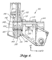
- the trunnion pin joint 90 includes eight basic elements: a trunnion pin 100, a landing gear fitting 110, an inboard nose wheel well fitting 130, a nose wheel well web 135, an outboard nose wheel well fitting 140, an inboard bushing 132 and an outboard bushing 142 and an outboard bushing retention clip 150.
- Trunnion pin 100 is secured to landing gear fitting 110 by a retention bolt 120 which passes through cylindrical bores in the landing gear fitting (not shown) and corresponding bores in the trunnion pin (not shown).
- Inboard nose wheel well fitting 130 and outboard nose wheel well fitting 140 are mounted on opposite sides of nose wheel well web 135.
- outboard bushing 142 is fitted into an opposite cylindrical bore in outboard nose wheel well fitting 140.
- Both outboard bushing 142 and inboard bushing 132 concentrically receive trunnion pin 100.
- Nose wheel well web 135 has an opening adapted to clear trunnion pin 100.
- both inboard and outboard bushings 132 and 142 have lubrication channels 148 formed in their inside surfaces to allow continuous lubrication of the trunnion pin and bushing surfaces. Lubricant is replenished to these channels through a lubrication fitting 146.
- Both inboard and outboard bushings 132 and 142 have outer flanges 133 and 149 respectively.
- Retaining clip 150 clamps down on an outer flange 149 of outboard bushing 142 and prevents it from migrating outboard and away from the trunnion pin joint.
- Figure 5 is a view of the trunnion pin joint 90 from the outside of the nose wheel well and it shows that retaining clip 150 is secured to outboard nose wheel well fitting 140 by retaining clip bolt 152.
- Figs. 1 and 2 landing gear 12 shock strut assembly 10 drag brace members 20 trunnion pins 30 bushings 40 landing gear support fittings 45 self-lubricating bearing 50 cylindrical steel pin 60 cylindrical bushing 70 Figs. 3, 4 and 5 trunnion pin joint 90 trunnion pin 100 landing geaar fitting 110 shims 115 retention bolt 120 inboard outboard nose wheel well fitting 130/140 inboard bushing 132 inboard bushing outer flange 133 wheel well web 135 outboard bushing 142 lubrification fitting 146 lubrification channels 148 outboard bushing outer flange 149 retaining clip 150 retaining clip bolt 152
Landscapes
- Engineering & Computer Science (AREA)
- Mechanical Engineering (AREA)
- Aviation & Aerospace Engineering (AREA)
- General Details Of Gearings (AREA)
- Gears, Cams (AREA)
- Gear Transmission (AREA)
- Snaps, Bayonet Connections, Set Pins, And Snap Rings (AREA)
Description
- The present invention relates to a nose gear installation and more particularly to a means for securing an aircraft nose landing gear assembly into the nose wheel well support structure of an aircraft. Specifically, the invention relates to an aircraft nose landing gear system as defined in the pre-characterizing part of claim 1.
- Prior art documents relating to aircraft landing gears do not include many details of the way in which the landing gear is pivotally mounted to the aircraft.
- For instance, EP-A-0 597 688 discloses a trolley for transporting and positioning a landing gear prior to installation on an aircraft. This document shows that a landing gear is positioned in the wheel well such as to align the fittings or bearings on the landing gear with corresponding bearings in the wheel well structure, after which a trunnion pin or pintle pin is inserted into the bearings. It is summarily stated that the bearings are then secured, without any indication of how this is achieved.
- US-A-5,337,976 schematically shows a landing gear pivotally mounted to an aircraft structure by means of a pin received in an opening in the structure. There is no indication of any bearing or fitting, nor of the way in which the pin is secured.
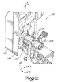
- As can be seen in Fig. 1, in prior commercial transport aircraft, specifically the Boeing 737-300/400/500 type aircraft, a nose landing gear system having the features of the pre-characterizing part of claim 1 is used. The
nose landing gear 12 generally consists of ashock strut assembly 10 anddrag brace members 20. The shock strut carries the wheels (not shown) and steering mechanism (not shown) and pivots abouttrunnion pins 30.Bushings 40 located in the side walls of the nose wheel well receive and support thetrunnion pins 30. Thedrag brace members 20 are used to unfold the landing gear and lock it in place whenbrace members 20 also brace the landing gear against forward and aft loads. Thedrag brace members 20 are secured to the nose wheel well support structure in a way substantially the same as the way in which theshock strut assembly 10 is secured to support structure. - The previous way of securing the nose
landing gear assembly 12 to the nose wheel well structure is as shown in Fig. 2. The old method employs joints at each of the landinggear support fittings 45 having a spherically mounted self lubricating bearing 50, acylindrical steel pin 60, and a correspondingcylindrical bushing 70 in thelanding gear assembly 12. Also at each joint location, a retaining nut, lock wire and washers (not shown in Fig. 2) are secured to the steel pin on the outboard (pressurized) side of the nose wheel well structure. - It is very difficult for a production worker or mechanic to access the outboard side of the nose wheel well at each of the joint locations and install retaining nuts, washers and lockwires. Consequently, the initial installation and subsequent removal and replacement of nose landing gear assemblies is a difficult and time consuming operation requiring considerable skill and effort. Accordingly, there is a need for an improved nose landing gear trunnion pin joint for installation of landing gear assemblies into the nose wheel well that does not require outboard retaining nuts, washers, or lockwires. Such a landing gear assembly would be designed so that a mechanic could install, remove or replace the nose landing assembly without accessing the outboard side of the nose wheel well.
- Nose landing gear trunnion pin arrangements used in other Boeing aircraft also generally rely on outboard side installed retaining nuts and the like as described above. The Boeing 777 series aircraft, however, use trunnion pins that install only from the inboard side. However, the landing gear support fittings in the nose wheel well of the Boeing 777 are single piece fittings designed to a safe life requirement. The Boeing 737 aircraft disclosed above use two-sided fittings that are designed to a fail safety requirement. These two-sided fittings require an inboard bushing and an outboard bushing and so, because an unrestrained outboard bushing could migrate outboard, trunnion pins were supplied with outboard retaining nuts.
- The present invention has for its object to provide a landing gear trunnion pin joint solving the aforementioned trunnion pin joint problem and to provide for simplified manufacture, installation and removal of the nose gear.
- In accordance with the present invention, this object is attained by an aircraft nose landing gear system as defined in claim 1.
- Preferred embodiments of the aircraft nose landing gear system of the invention form the subject matter of dependent claims 2 to 7.
-
- Fig. 1 is illustrative of a general aircraft nose gear assembly;
- Fig. 2 is illustrative of the prior method of securing the nose landing gear assembly to the nose wheel well structure;
- Fig. 3 is illustrative of the eight elements compromising the present trunnion pin joint;
- Fig. 4 is illustrative in more detail of the relationship of the elements shown in Fig. 3, including the manner in which the retaining clip functions to prevent outward migration of the outboard bushing; and
- Fig. 5 is a view of the trunnion pin joint from the outside of the nose wheel well.
-
- Turning now to Figs. 3 and 4, it can be seen that the
trunnion pin joint 90 according to the present system includes eight basic elements: atrunnion pin 100, alanding gear fitting 110, an inboard nose wheel well fitting 130, a nosewheel well web 135, an outboard nose wheel well fitting 140, aninboard bushing 132 and an outboard bushing 142 and an outboardbushing retention clip 150. Trunnionpin 100 is secured to landing gear fitting 110 by aretention bolt 120 which passes through cylindrical bores in the landing gear fitting (not shown) and corresponding bores in the trunnion pin (not shown). Inboard nose wheel well fitting 130 and outboard nose wheel well fitting 140 are mounted on opposite sides of nosewheel well web 135. As can be seen in the same way, outboard bushing 142 is fitted into an opposite cylindrical bore in outboard nose wheel well fitting 140. Both outboard bushing 142 and inboard bushing 132 concentrically receivetrunnion pin 100. Nosewheel well web 135 has an opening adapted to cleartrunnion pin 100. Aslanding gear fitting 110 is fitted up against inboard nose wheel well fitting 130 it is sometimes necessary to addshims 115. Further, both inboard andoutboard bushings lubrication channels 148 formed in their inside surfaces to allow continuous lubrication of the trunnion pin and bushing surfaces. Lubricant is replenished to these channels through a lubrication fitting 146. Both inboard andoutboard bushings outer flanges clip 150 clamps down on anouter flange 149 of outboard bushing 142 and prevents it from migrating outboard and away from the trunnion pin joint. Figure 5 is a view of thetrunnion pin joint 90 from the outside of the nose wheel well and it shows that retainingclip 150 is secured to outboard nose wheel well fitting 140 by retainingclip bolt 152. - Reference numerals utilized in identifying component structure in the aforementioned detailed description:
Figs. 1 and 2 landing gear 12 shock strut assembly 10 drag brace members 20 trunnion pins 30 bushings 40 landing gear support fittings 45 self-lubricating bearing 50 cylindrical steel pin 60 cylindrical bushing 70 Figs. 3, 4 and 5 trunnion pin joint 90 trunnion pin 100 landing geaar fitting 110 shims 115 retention bolt 120 inboard outboard nose wheel well fitting 130/140 inboard bushing 132 inboard bushing outer flange 133 wheel well web 135 outboard bushing 142 lubrification fitting 146 lubrification channels 148 outboard bushing outer flange 149 retaining clip 150 retaining clip bolt 152 - While a preferred embodiment of the invention has been illustrated and described, variations will be apparent to those skilled in the art Accordingly, the invention is not to be limited to the specific embodiment illustrated and described, and the true scope of the invention is to be determined by reference to the following claims.
Claims (7)
- An aircraft nose landing gear system comprising:characterized in that said retention means include a retaining clip (150).a nose wheel well structure including a nose wheel well web (135) on each side of the nose wheel well, anda landing gear assembly pivotally mounted in each nose wheel well web (135) by means of at least one trunnion pin joint (90),said trunnion pin joint (90) including a trunnion pin (100), a landing gear fitting (110), at least one nose wheel well fitting (130,140) mounted to the nose wheel well web (135), an inboard bushing (132) and an outboard bushing (142) arranged in said at least one nose wheel well fitting (130,140), and retention means for retaining the outboard bushing (142),
- The aircraft nose landing gear system as claimed in claim 1, characterized in that said outboard bushing (142) includes an outer flange (149) and said retaining clip (150) is arranged to clamp down on said outer flange (149).
- The aircraft nose landing gear system as claimed in claim 1 or 2, characterized in that said retaining clip (150) is secured to said at least one nose wheel well fitting (130,140) by a retaining clip bolt (152).
- The aircraft nose landing gear system as claimed in any of the preceding claims, characterized by an inboard nose wheel well fitting (130) and an outboard nose wheel well fitting (140) mounted on opposite sides of each nose wheel well web (135), said inboard and outboard bushings (132,142) being symmetrically mounted in said inboard and outboard nose wheel well fittings (130,140), respectively.
- The aircraft nose landing gear system as claimed in any of the preceding claims, characterized in that said trunnion pin (100) is secured to said landing gear fitting (110) by a retention bolt (120) passing through bores in the landing gear fitting (110) and trunnion pin (100).
- The aircraft nose landing gear system as claimed in any one of the preceding claims, characterized in that said landing gear assembly includes a shock strut assembly and drag brace members, both said shock strut assembly and said drag brace members being shorter than a space between said nose wheel well webs (135), both said shock strut assembly and said drag brace members having two fittings (110), one at each end thereof, and both said shock strut assembly and said drag brace members being mounted to each nose wheel well web (135) by said trunnion pin (100) passing through one of said shock strut or drag brace fittings (110) and through the corresponding inboard and outboard bushings (132,142), respectively.
- The aircraft nose landing gear system as claimed in claim 6, characterized by shims (115) closing a gap between said landing gear fittings (110) and said inboard bushings (132).
Applications Claiming Priority (2)
| Application Number | Priority Date | Filing Date | Title |
|---|---|---|---|
| US918336 | 1997-08-26 | ||
| US08/918,336 US6016995A (en) | 1997-08-26 | 1997-08-26 | Aircraft nose landing gear |
Publications (3)
| Publication Number | Publication Date |
|---|---|
| EP0899191A2 EP0899191A2 (en) | 1999-03-03 |
| EP0899191A3 EP0899191A3 (en) | 1999-03-31 |
| EP0899191B1 true EP0899191B1 (en) | 2003-10-15 |
Family
ID=25440207
Family Applications (1)
| Application Number | Title | Priority Date | Filing Date |
|---|---|---|---|
| EP98202425A Expired - Lifetime EP0899191B1 (en) | 1997-08-26 | 1998-07-17 | Aircraft nose landing gear |
Country Status (5)
| Country | Link |
|---|---|
| US (2) | US6016995A (en) |
| EP (1) | EP0899191B1 (en) |
| CN (1) | CN1093066C (en) |
| CA (1) | CA2243075C (en) |
| DE (1) | DE69818927T2 (en) |
Families Citing this family (20)
| Publication number | Priority date | Publication date | Assignee | Title |
|---|---|---|---|---|
| FR2793210B1 (en) * | 1999-05-05 | 2001-09-21 | Aerospatiale Airbus | STRUCTURE FOR ATTACHING A LANDING GEAR TO AN AIRCRAFT FUSELAGE |
| US7264398B2 (en) | 2001-08-24 | 2007-09-04 | The Boeing Company | Truck pivot joint bearing and method of lubricating |
| FR2833572B1 (en) * | 2001-12-18 | 2004-04-02 | Airbus France | METHOD AND DEVICE FOR MOUNTING A LANDING GEAR ON AN AIRCRAFT STRUCTURE AND AIRCRAFT COMPRISING SUCH A TRAIN |
| FR2840585B1 (en) * | 2002-06-10 | 2005-02-04 | Airbus France | DEVICE FOR MOUNTING A LANDING TRAIN ON AN AIRCRAFT STRUCTURE |
| US6824100B1 (en) * | 2003-08-15 | 2004-11-30 | The Boeing Company | Airplane landing gear |
| FR2893589B1 (en) * | 2005-11-21 | 2009-06-05 | Airbus France Sas | AIRCRAFT AIR CLEANER COMPRISING A COUNTERFILE AND AIRCRAFT MANEUVER DEVICE COMPRISING SAME |
| FR2893588B1 (en) * | 2005-11-21 | 2008-02-01 | Airbus France Sas | TRAIN BOX WITH HOUSING STRUCTURE |
| US7546979B1 (en) * | 2006-09-15 | 2009-06-16 | The Boeing Company | Trapezoidal panel pin joint allowing free deflection between fuselage and wing |
| FR2917369B1 (en) * | 2007-06-15 | 2009-08-07 | Airbus France Sas | LANDING TRAIN BOX WITH REDUCED SIZE |
| CA2712671C (en) * | 2008-01-28 | 2013-01-08 | Bell Helicopter Textron Inc. | Split pivot fitting for helicopter landing gear |
| FR2944076B1 (en) * | 2009-04-06 | 2012-09-21 | Messier Dowty Sa | SELECTIVE EFFORT TRANSMISSION DEVICE, AND A REALIZER USING THE SAME |
| GB201110483D0 (en) * | 2011-06-21 | 2011-08-03 | Airbus Operations Ltd | Pivot joint assembly |
| FR2983826B1 (en) * | 2011-12-12 | 2013-12-20 | Airbus Operations Sas | FRONT STRUCTURE IMPROVED WITH COMPARTMENT FOR LANDING TRAIN. |
| US9140302B2 (en) | 2013-06-13 | 2015-09-22 | The Boeing Company | Joint bearing lubricant system |
| US9821904B2 (en) * | 2014-11-10 | 2017-11-21 | Goodrich Corporation | Landing gear with structural load path diverter bracket |
| US10598251B2 (en) * | 2017-04-14 | 2020-03-24 | The Boeing Company | Vibration damping link and method therefore |
| US11312483B2 (en) | 2019-05-10 | 2022-04-26 | Goodrich Corporation | Landing gear with hydraulic fluid channels |
| US11167865B2 (en) * | 2019-05-10 | 2021-11-09 | Goodrich Corporation | Additively manufactured lubrication channels |
| CN110466733B (en) * | 2019-08-12 | 2022-07-19 | 中国航空工业集团公司沈阳飞机设计研究所 | Unmanned aerial vehicle undercarriage installing frame |
| US11897602B2 (en) * | 2021-03-17 | 2024-02-13 | The Boeing Company | Support structure for an aircraft landing gear |
Family Cites Families (10)
| Publication number | Priority date | Publication date | Assignee | Title |
|---|---|---|---|---|
| GB576547A (en) * | 1944-09-12 | 1946-04-09 | Walter Raylor | Improvements in pipe or tube couplings |
| US3393883A (en) * | 1966-06-06 | 1968-07-23 | Ted Smith Aircraft Company Inc | Aircraft landing gear |
| US4392623A (en) * | 1980-12-22 | 1983-07-12 | The Boeing Company | Fused connection adapted to fail under different overloads acting in different directions |
| FR2502578A1 (en) * | 1981-03-27 | 1982-10-01 | Messier Hispano Sa | LANDING TRAIN TYPE TRIPODE |
| US4720063A (en) * | 1985-09-30 | 1988-01-19 | The Boeing Company | Main landing gear with variable length drag brace |
| US4770372A (en) * | 1986-09-30 | 1988-09-13 | The Boeing Company | Two-stage aircraft landing gear |
| US5110068A (en) * | 1990-12-20 | 1992-05-05 | The Boeing Company | Multi-axled propped landing gear |
| FR2689087B1 (en) * | 1992-03-31 | 1994-05-13 | Messier Bugatti | LIFTABLE AERODYNES LANDER, PARTICULARLY FOR HELICOPTERS. |
| JP3147539B2 (en) * | 1992-10-05 | 2001-03-19 | 本田技研工業株式会社 | Aircraft landing gear |
| GB9223716D0 (en) * | 1992-11-12 | 1992-12-23 | British Aerospace | An aircraft landing gear trolley |
-
1997
- 1997-08-26 US US08/918,336 patent/US6016995A/en not_active Expired - Lifetime
-
1998
- 1998-07-13 CA CA002243075A patent/CA2243075C/en not_active Expired - Lifetime
- 1998-07-17 DE DE69818927T patent/DE69818927T2/en not_active Expired - Lifetime
- 1998-07-17 EP EP98202425A patent/EP0899191B1/en not_active Expired - Lifetime
- 1998-08-18 CN CN98118388A patent/CN1093066C/en not_active Expired - Lifetime
-
1999
- 1999-08-05 US US09/368,556 patent/US6129310A/en not_active Expired - Lifetime
Also Published As
| Publication number | Publication date |
|---|---|
| EP0899191A2 (en) | 1999-03-03 |
| CA2243075A1 (en) | 1999-02-26 |
| CN1093066C (en) | 2002-10-23 |
| CA2243075C (en) | 2006-03-21 |
| DE69818927D1 (en) | 2003-11-20 |
| DE69818927T2 (en) | 2004-05-19 |
| US6129310A (en) | 2000-10-10 |
| EP0899191A3 (en) | 1999-03-31 |
| CN1209406A (en) | 1999-03-03 |
| US6016995A (en) | 2000-01-25 |
Similar Documents
| Publication | Publication Date | Title |
|---|---|---|
| EP0899191B1 (en) | Aircraft nose landing gear | |
| EP0741074A1 (en) | Three link failsafe engine mount | |
| EP2660120B1 (en) | Railway vehicle bogie | |
| EP2921727B1 (en) | U-shaped clip for fixing a link rod within an aircraft clevis | |
| US4575145A (en) | Differential axle for railroad car | |
| US5897107A (en) | Roller bushing assembly | |
| PL177558B1 (en) | Articulated vehicle and articulated coupling arrangement therefor | |
| EP0504238B1 (en) | Vehicle axle beam and brake assembly | |
| EP0520121B1 (en) | Steering knuckle | |
| EP0332311A1 (en) | Self-adjusting bearing | |
| US3458214A (en) | Rotary bearing | |
| US4083610A (en) | Bearing assembly utilizing a tapered bushing holder | |
| US11273923B2 (en) | Fail-safe engine support system | |
| US20020133950A1 (en) | Hole misalignment compensation system and method | |
| US11479104B2 (en) | System and method for gas turbine engine mount with seal | |
| US20080095481A1 (en) | Differential wheel mounting for a railroad car | |
| US6413048B1 (en) | Elastomeric bearing | |
| US6604794B1 (en) | Uni-pilot hub/drum system | |
| US6595085B1 (en) | Differential bearing cap | |
| US20210023927A1 (en) | System and method for gas turbine engine mount with seal | |
| EP0251545A1 (en) | Brake assemblies | |
| CN211619770U (en) | Rotating shaft assembly and rotatable travelling mechanism | |
| US2882079A (en) | Radial and longitudinal stressabsorbing suspension pivot | |
| CN221091216U (en) | Flap system for an aircraft | |
| US7316436B1 (en) | Differential wheel mounting for railroad car |
Legal Events
| Date | Code | Title | Description |
|---|---|---|---|
| PUAI | Public reference made under article 153(3) epc to a published international application that has entered the european phase |
Free format text: ORIGINAL CODE: 0009012 |
|
| PUAL | Search report despatched |
Free format text: ORIGINAL CODE: 0009013 |
|
| AK | Designated contracting states |
Kind code of ref document: A2 Designated state(s): DE FR GB |
|
| AX | Request for extension of the european patent |
Free format text: AL;LT;LV;MK;RO;SI |
|
| AK | Designated contracting states |
Kind code of ref document: A3 Designated state(s): AT BE CH CY DE DK ES FI FR GB GR IE IT LI LU MC NL PT SE |
|
| AX | Request for extension of the european patent |
Free format text: AL;LT;LV;MK;RO;SI |
|
| 17P | Request for examination filed |
Effective date: 19990922 |
|
| AKX | Designation fees paid |
Free format text: DE FR GB |
|
| 17Q | First examination report despatched |
Effective date: 20020806 |
|
| GRAH | Despatch of communication of intention to grant a patent |
Free format text: ORIGINAL CODE: EPIDOS IGRA |
|
| RIN1 | Information on inventor provided before grant (corrected) |
Inventor name: DONG, ANNETTE K. Inventor name: DEPENBUSCH, ROGER A. Inventor name: SQUIRES, THOMAS J. |
|
| GRAS | Grant fee paid |
Free format text: ORIGINAL CODE: EPIDOSNIGR3 |
|
| GRAA | (expected) grant |
Free format text: ORIGINAL CODE: 0009210 |
|
| AK | Designated contracting states |
Kind code of ref document: B1 Designated state(s): DE FR GB |
|
| REG | Reference to a national code |
Ref country code: GB Ref legal event code: FG4D |
|
| REF | Corresponds to: |
Ref document number: 69818927 Country of ref document: DE Date of ref document: 20031120 Kind code of ref document: P |
|
| ET | Fr: translation filed | ||
| PLBQ | Unpublished change to opponent data |
Free format text: ORIGINAL CODE: EPIDOS OPPO |
|
| PLBI | Opposition filed |
Free format text: ORIGINAL CODE: 0009260 |
|
| PLAX | Notice of opposition and request to file observation + time limit sent |
Free format text: ORIGINAL CODE: EPIDOSNOBS2 |
|
| 26 | Opposition filed |
Opponent name: AIRBUS SAS Effective date: 20040715 |
|
| PLAX | Notice of opposition and request to file observation + time limit sent |
Free format text: ORIGINAL CODE: EPIDOSNOBS2 |
|
| PLBB | Reply of patent proprietor to notice(s) of opposition received |
Free format text: ORIGINAL CODE: EPIDOSNOBS3 |
|
| PLBD | Termination of opposition procedure: decision despatched |
Free format text: ORIGINAL CODE: EPIDOSNOPC1 |
|
| PLBP | Opposition withdrawn |
Free format text: ORIGINAL CODE: 0009264 |
|
| PLBM | Termination of opposition procedure: date of legal effect published |
Free format text: ORIGINAL CODE: 0009276 |
|
| STAA | Information on the status of an ep patent application or granted ep patent |
Free format text: STATUS: OPPOSITION PROCEDURE CLOSED |
|
| 27C | Opposition proceedings terminated |
Effective date: 20070312 |
|
| REG | Reference to a national code |
Ref country code: FR Ref legal event code: PLFP Year of fee payment: 19 |
|
| REG | Reference to a national code |
Ref country code: FR Ref legal event code: PLFP Year of fee payment: 20 |
|
| PGFP | Annual fee paid to national office [announced via postgrant information from national office to epo] |
Ref country code: FR Payment date: 20170726 Year of fee payment: 20 Ref country code: DE Payment date: 20170727 Year of fee payment: 20 Ref country code: GB Payment date: 20170727 Year of fee payment: 20 |
|
| REG | Reference to a national code |
Ref country code: DE Ref legal event code: R071 Ref document number: 69818927 Country of ref document: DE |
|
| REG | Reference to a national code |
Ref country code: GB Ref legal event code: PE20 Expiry date: 20180716 |
|
| PG25 | Lapsed in a contracting state [announced via postgrant information from national office to epo] |
Ref country code: GB Free format text: LAPSE BECAUSE OF EXPIRATION OF PROTECTION Effective date: 20180716 |