EP0898662B1 - Friction clutch with wear adjusting device, in particular for motor vehicles - Google Patents
Friction clutch with wear adjusting device, in particular for motor vehicles Download PDFInfo
- Publication number
- EP0898662B1 EP0898662B1 EP97919117A EP97919117A EP0898662B1 EP 0898662 B1 EP0898662 B1 EP 0898662B1 EP 97919117 A EP97919117 A EP 97919117A EP 97919117 A EP97919117 A EP 97919117A EP 0898662 B1 EP0898662 B1 EP 0898662B1
- Authority
- EP
- European Patent Office
- Prior art keywords
- fact
- worm
- friction clutch
- return
- clutch according
- Prior art date
- Legal status (The legal status is an assumption and is not a legal conclusion. Google has not performed a legal analysis and makes no representation as to the accuracy of the status listed.)
- Expired - Lifetime
Links
Images


Classifications
-
- F—MECHANICAL ENGINEERING; LIGHTING; HEATING; WEAPONS; BLASTING
- F16—ENGINEERING ELEMENTS AND UNITS; GENERAL MEASURES FOR PRODUCING AND MAINTAINING EFFECTIVE FUNCTIONING OF MACHINES OR INSTALLATIONS; THERMAL INSULATION IN GENERAL
- F16D—COUPLINGS FOR TRANSMITTING ROTATION; CLUTCHES; BRAKES
- F16D13/00—Friction clutches
- F16D13/58—Details
- F16D13/75—Features relating to adjustment, e.g. slack adjusters
- F16D13/757—Features relating to adjustment, e.g. slack adjusters the adjusting device being located on or inside the clutch cover, e.g. acting on the diaphragm or on the pressure plate
-
- F—MECHANICAL ENGINEERING; LIGHTING; HEATING; WEAPONS; BLASTING
- F16—ENGINEERING ELEMENTS AND UNITS; GENERAL MEASURES FOR PRODUCING AND MAINTAINING EFFECTIVE FUNCTIONING OF MACHINES OR INSTALLATIONS; THERMAL INSULATION IN GENERAL
- F16D—COUPLINGS FOR TRANSMITTING ROTATION; CLUTCHES; BRAKES
- F16D13/00—Friction clutches
- F16D13/58—Details
- F16D13/583—Diaphragm-springs, e.g. Belleville
-
- F—MECHANICAL ENGINEERING; LIGHTING; HEATING; WEAPONS; BLASTING
- F16—ENGINEERING ELEMENTS AND UNITS; GENERAL MEASURES FOR PRODUCING AND MAINTAINING EFFECTIVE FUNCTIONING OF MACHINES OR INSTALLATIONS; THERMAL INSULATION IN GENERAL
- F16D—COUPLINGS FOR TRANSMITTING ROTATION; CLUTCHES; BRAKES
- F16D13/00—Friction clutches
- F16D13/58—Details
- F16D13/70—Pressure members, e.g. pressure plates, for clutch-plates or lamellae; Guiding arrangements for pressure members
Definitions
- the present invention relates to a friction clutch, especially for a motor vehicle, and relates more particularly to a clutch fitted with a compensation of wear due in particular to the wear of the linings of friction, said device, hereinafter referred to as a take-up device wear, operating as and when said linings wear.
- a conventional friction clutch usually has a reaction plate, possibly in two parts for training a damping flywheel, set in rotation on a first shaft, usually a driving shaft such as the crankshaft of the engine internal combustion, and supporting by its external periphery a cover to which at least one pressure plate is attached.
- the pressure plate is integral in rotation with the cover and of the reaction plate while being able to move axially under the use of elastic means with controlled axial action, usually a metal diaphragm resting on the cover, while a friction disc, bearing linings friction at its outer periphery, integral in rotation with a tree, usually a driven tree such as the input shaft of the gearbox, is interposed between the pressure plate and the reaction plate so as to be clamped together when the clutch is in the engagement position.
- the diaphragm controls the axial displacement of the pressure plate when actuated by a clutch release bearing. More precisely the peripheral part of the diaphragm forms the above-mentioned elastic means or engagement means controlled by declutching means, here the fingers of the diaphragm.
- the declutching means allow, when actuated by the clutch release bearing, to counteract the action of the declutching means.
- a one-way coupling arranged between the worm and the axis that supports it allows it to maintain its position in rotation after each adjustment.
- Such a device has the following disadvantages: the armament, which is carried by the clutch cover is likely to be driven in rotation by a lever itself controlled by the release bearing; therefore, the clutch release bearing must be specifically adapted to the control of said lever and is bulky axially; through elsewhere, when the clutch release bearing is caused to be moved axially beyond the stroke just necessary for the operation of declutching, the catch-up operation is carried out when there is no no wear, which is dangerous because it can lead to blockage of the clutch which ends up being unable to be disengaged.
- a friction clutch comprising a reaction plate intended to be wedged in rotation on a shaft leading, a friction disc, carrying on its outer periphery friction linings, intended to be wedged in rotation on a shaft led, pressure plate, cover fixed on the reaction plate, elastic means with action axial acting between, on the one hand, the cover and, on the other hand, the pressure plate by via support means, the pressure plate being integral in rotation with the cover while being able to move axially with respect to it and being subjected to the action of elastic recall means reminding the pressure plate axially towards the cover, said clutch also comprising a device for wear compensation comprising ramp means arranged circumferentially, placed axially between the means support and pressure plate and adapted to be driven in rotation thanks to a toothing that they carry on their periphery and with which a screw cooperates endless tangentially arranged means drive in rotation of the worm being provided, made operational by wear of the
- the present invention aims to overcome these drawbacks.
- the rotation drive means, the augers are controlled by the diaphragm via an operating tab or finger, forming an operating part, whose stroke, during the declutching operation, is limited by a so-called control stop.
- the ramp means consist of a ring having inclined and circumferentially distributed ramps; preferably, the pressure plate has studs or ramps intended to cooperate with the ramps of the ramp means.
- said ring also has zones of support constituted by the rounded upper edge of stampings arranged in circular arcs centered on the axis of the clutch and placed radially outside relative to the ramps; thanks to this arrangement, on the one hand, the support zones are large length and, on the other hand, the ramps can be numerous as well, contact pressures are minimized.
- the ramp means have an axial rim provided with ventilation openings; advantageously, the means to ramps have an axial rim centering the ramp means by compared to the pressure plate.
- the worm is slidably mounted according to its axis being subjected to the action of an elastic means called catching up and, when it is moved along its axis, it drives in circumferential rotation said ramp means; of preferably, the load of the elastic take-up means increases with the wear of the friction linings and said axial displacement is obtained by action of the elastic catch-up means when its load is high enough to overcome the friction force caused by the axial force coming from the elastic return means to which said ramp means are subjected, the clutch being disengaged; in variant, the pressure plate stroke is limited in the direction release to release the ramp means from the axial force from elastic return means.
- the elastic take-up means is a spring helical surrounding an axis which carries the worm; ways drive in rotation of the worm are constituted by a ratchet wheel secured to the worm.
- the axis carrying the worm and the spring helical is supported by the support.
- the non-return means are constituted by a ratchet which cooperates with the ratchet wheel.
- the clutch can be of the pushed type, the diaphragm being secured to the cover by balusters; it can also be of the type drawn.
- the support is U-shaped with a core and two wings intended to support the axis; support wings extend in L-shaped arms extending towards each other perpendicular to the core and each ending in one end C-shaped set on the edge of a transverse opening of the cover; this opening is provided in a radial projection defining a housing for the game take-up device.
- the support is adapted to receive an elastic, shaped member butt stock, each end of which has a return to the interior; the longer part of the butt believes in width towards its end ending in a return which carries at the end a control tab; the smallest part length of the stock at its return forming a non-return pawl which generally extends parallel to the control tab in being at a distance from it so that when the organ elastic and the ratchet wheel are mounted in the support, the non-return pawl and control tab each cooperate with a tooth foot; for its mounting in the support, the organ elastic sideways carries angled arms arranged on both sides and other of the elastic part in the form of a butt, orthogonally relative to it, and the free end of the arms angled carries holes for the axis.
- the worm and the ratchet wheel are cut in a single piece of simple and economical production.
- the support equipped with the worm, the ratchet wheel, the elastic member, of the spring and of the axis constitutes a subset ready to install in the cover.
- the diaphragm carries at its periphery a radial appendage called actuator extending radially outside the part Belleville washer of the diaphragm to cooperate with the enlarged area of the very long part of the elastic member.
- the teeth of the ratchet wheel are made so that when of the clutch release race new friction linings, the end of the control tongue does not skip a tooth, advantageously the non-return pawl holding the ratchet wheel.
- the teeth of the ratchet wheel are made so that when a minimum declutching stroke defined by construction, and apart from the control stop, the end of the control tab jumps a tooth.
- the support is U-shaped, having a core and two wings, each carrying a hole adapted to receive the axis of the device, the soul carrying laterally a lug with a directed square outwardly intended to be fixed on the outer edge of the cover;
- the wings of the support have, on the side opposite to that where the tab is located, an axial extension whose end is folded outwards to form a mounting bracket parallel to the leg above and intended to be fixed to the bottom of the cover; on their edge facing the soul, said extensions are provided with returns directed towards each other in extending generally parallel to the core and intended for constitute stops; the ends facing each other of said returns are at a sufficient distance from each other to allow, without interfering, the movement of the actuator during clutch and declutching operations.
- the elastic member is in the form of a jumper and includes a body elongated plane carrying at each of its ends an arm provided with a hole adapted to receive the axis; on one of its longitudinal edges, body extends obliquely on the same side as the one where the arms are placed; notches in the body limit extension relative to body ends carrying arms; the free end of the extension is provided with a return which extends along a control tab extending in direction of the body being generally parallel to it; a cut-out is provided in the extension; thanks to this cut, and notches in the body, a non-return ratchet is produced composed of at least two blades of slightly different lengths.
- the elastic member comprises two separate parts ; a first part, for the non-return function, is a stirrup in U shape with two wings carrying holes to support the axis; the soul of this stirrup is, on one of its sides, in the vicinity of its middle part, cut into at least two blades which extend in a direction parallel to that of the wings and extend according to square returns directed on the same side as the wings by relative to the core generally perpendicular to said core; said returns have slightly different lengths and blades constitute a non-return pawl intended to cooperate with the ratchet wheel.
- the second part for the control function of the ratchet wheel, is a threadlike spring, associated with a worn finger by a cylindrical sleeve fitted on an axis; the sleeve and its finger are secured in rotation to the shaft by a pin passing diametrically through the sleeve and the shaft, protruding by one side of the sleeve to make a support for the bottom of a open loop of a threadlike spring shaped like a hook, said filiform spring being adapted to subject the finger control at a torque applying the tip of the finger to the ratchet wheel.
- the support comprises wings which are provided on their edge opposite the core of open notches on the side of the holes for the axis, these notches making a slight angle with the plane of the core and having a width adapted to receive the axis of the finger of ordered.
- the pressure plate presents towards its outer periphery a recess facing the cover and for housing the wear take-up device.
- control finger is directly actuated by the outer periphery of the diaphragm.
- the teeth of the ratchet wheel are cut to the outer periphery of the worm screw thread.
- This provision is economical and simple; the piece is lighter, less complex ; the ratchet wheel can thus have more teeth; the axial size is smaller; machining is easier and reliability is better.
- the support is in general L shape having two wings, one of which is intended to support the axis and the other of which is intended for fixing the support on the cover; the wing supporting the axis crosses the diaphragm between two of its fingers.
- the elastic member is in the general form of rider and includes a flat body bearing at each of its ends an arm provided with a hole adapted to receive the axis; both arms are parallel and extend on the same side and overall perpendicular to the body; on one of its edges longitudinal, the body extends in an extension which includes a first part in the extension of the body, a second part directed in the opposite direction to that of the arms by making a acute angle with the body, a third part forming a U with the second part and extending parallel thereto, and a fourth part directed towards the body while being parallel to this one, at a slightly higher level so that it extends between arms; this fourth part directly or indirectly constitutes a control tab; a cutout in each of the arms limits the travel of the control tongue, parallel to the body, at least away from the body; on its longitudinal edge opposite to where the extension is located, the body carries a ratchet check valve made up of at least two length blades different, the difference of these lengths being of the order of one half tooth.
- the elastic take-up means is a spring wrapped around the axis being placed in a housing provided for the inside of the ratchet or worm wheel; alternatively, the elastic catching means is on the outside of the worm being produced in the form of an elastic stirrup overlapping said screw.
- the support consists of at least one strip elastic linked, on one side, to the axis around which is mounted rotation of the worm and, on the other side, to the cover.
- the axis is inclined, relative to a plane perpendicular to the axis of the clutch, at an angle equal to that of the worm screw thread.
- the clutch comprises several devices for wear compensation, for example three, equally distributed circumferentially.
- the diaphragm clutch 3, 53, 203 comprises a cover 2, 52, 202 of hollow form.
- the cover is metallic by being in pressed sheet metal.
- This cover has a bottom and means for fixing it to a reaction plate, possibly divided to form a damping flywheel.
- the cover 2, 52 is generally in the form of a deep dish and comprises at its outer periphery a radial rim forming fastening means from the cover to the reaction plate, said rim being provided with holes for the passage of fasteners, such as screws, cover to reaction plate.
- the means of fixing the cover consists of an annular orientation skirt axial extending a radial rim with holes for passage of fasteners, such as screws, from cover 202 to tray of reaction.
- the clutch is of the pushed type, that is to say, using a stopper release, not shown, act by pushing on the internal end diaphragm fingers 3, 53 to disengage (disengage) the clutch, the said fingers forming declutching means for counteract, under the action of the clutch release bearing, the action of engagement means constituted by the peripheral shape part annular diaphragm.
- the bottom of the cover 2, 52 carries, on the one hand, a primary support consisting for example of a rod, or in Figures 1, 21, 28, 35 in a stamped formed in the bottom of the cover at the internal periphery thereof, and, on the other hand, opposite the primary support, secondary support in the form of baluster heads 8, 58 (FIGS.
- the clutch is of the pulled type so that it is necessary to act in traction on the inner end of the diaphragm fingers 203 to disengage (disengage) the clutch.
- the external peripheral part of the Belleville washer of the diaphragm rests on the bottom of the cover, in Figures 40 and 48 on an unreferenced rod worn by the outer periphery of the bottom of the cover, alternatively on a stamped formed in said bottom.
- the internal peripheral part of this Belleville washer is in contact with a support 214 described below.
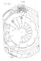
- a mechanism friction clutch in particular for a motor vehicle, which comprises a pressure plate 1 intended to cooperate with a disc friction not shown, carrying at its outer periphery friction linings, which cooperates itself with a plate of reaction.
- the reaction plate not shown, is intended to be stalled in rotation on a driving shaft, such as the crankshaft of the internal combustion engine.
- the friction disc is integral in rotation of a driven shaft such as the input shaft of the gearbox speeds.
- the friction disc and the reaction plate are shown schematically for example in the document US-A-5,090,536 or FR-A-2,599,446, the friction disc can be rigid or progressive type.
- the pressure plate 1 is integral in rotation with a cover 2 of hollow form by means of tabs tangentials 9 which, elastic, constitute at the same time means for returning the pressure plate 1 to the cover 2, here metal in pressed sheet metal.
- the baluster 8 has a head contoured offering secondary support to the diaphragm opposite a primary support formed by stamping the bottom of the cover 2 of hollow form.
- the diaphragm is pivotally mounted between these supports.
- the means elastics with axial action 3 forming engagement means by through the ring-shaped peripheral part Belleville diaphragm, in a position independent of wear friction disc linings, and to a lesser extent the wear of the pressure 1 and reaction plates, the faces of which, friction, wear out in contact with the disc linings, it a wear take-up device 10 is provided.
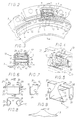
- the wear take-up device 10 comprises means for ramps 11 arranged circumferentially; more specifically, these ramp means 11, better visible in FIGS. 2 and 10, are consisting of a sheet metal ring cut and stamped so as to have ramps 15 arranged circumferentially; said ring also has support zones 14 constituted by the rounded upper edge of stamped in circular arcs centered on the clutch axis and placed radially outside with respect to on the ramps 15.
- the pressure plate 1 presents, here coming from molding, on its face turned towards the bottom of the cover 2, radially beyond the posts 8, studs 4 distributed circumferentially at a distance from each other which corresponds to that which separates circumferentially two successive ramps 15, the studs 4 being intended to cooperate each with a ramp 15.
- the ramp means 11 are placed axially between the diaphragm 3 and the pressure plate 1 so that the studs 4 receive the ramps 15 and the diaphragm 3 cooperates with the zones support 14 which thus constitute the support means by through which the diaphragm 3 acts on the plate of pressure 1.
- This arrangement is economical and simple, the means to ramps 11 being metallic and obtained by stamping.
- One of the support zones 14 of the ramp means 11 is extended, Figures 1 and 13, at its outer periphery by a parallel flange 16 to the axis of the clutch ending in a transverse return 17, that is to say extending in a plane perpendicular to the axis of the clutch, provided at its periphery with a toothing 18, so that the support zones 14 can be continuous and the rim is centered by a boss-shaped excess thickness of the pressure plate 1.
- the axial flange 16 of the ramp means 11 has openings 16A, here of rectangular shape, facilitating their ventilation.
- the axial flange 16 is by its internal periphery in contact intimate with the external periphery of a boss of the plate of pressure so that the axial flange 16 centers the ramp means 11 relative to the pressure plate 1. More precisely the plate pressure 1 has at its outer periphery a split boss protruding towards the bottom of the cover. This shape boss ring serves as a centering device for the rim 16.
- the wear take-up device 10 also comprises a ratchet wheel 20 with inclined teeth 21 secured to an axle 22 which also carries a worm 13; the thread and the pitch of the screw endless 13 are adapted to the toothing 18 of the ramp means 11; the worm 13 is brought to cooperate with the toothing 18 in the conditions which will be described below.
- the axis 22 of the ratchet wheel 20 is rotated by a support 12, better visible in FIGS. 6 to 8, in cut sheet metal and folded, U-shaped having a core 19 and two wings 23, 24 intended to support the axis 22; for this purpose, each of the wings carries a hole circular 25 adapted to the diameter of the axis 22.
- the wings 23, 24 of the support 12 extend outwardly in L-shaped arms 27, 28 extending towards each other perpendicular to the core 19 and ending each, when the support 12 is mounted on the cover 2, by a shaped end of C, respectively 29 and 30, the two C-shaped ends 29 and 30 being arranged back to back in line with each other.
- the cover 2 has a radial projection 5 defining a housing for the wear take-up device 10; this housing communicates with the outside through a transverse opening 6 pierced in the transverse wall of the cover 2; the edges of this transverse opening 6 are adapted to receive the C-shaped ends 29 and 30 of the support 12 which are crimped onto these edges, as shown in Figure 3, and which thus fix the support 12 on the cover;
- Figures 1, 2 and 3 show that the support 12 fits perfectly in the housing, defined by the radial projection 5, said housing and the support 12, here metallic, having complementary shapes; at the junction between the transverse wall of the cover and the extension of the skirt cylindrical cover which limits said housing, an opening 7 facilitates ventilation of the device 10.
- the support 12 is mounted radially above the pressure plate 1.
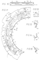
- the support 12 is adapted to receive an elastic member 31 of thinner than the support 12, better visible on the Figures 4 and 5;
- the elastic member 31, here metallic, is shaped butt stock, each end of which has a return to the interior; more precisely, the portion 32 of greater length of the stock increases in width towards its end ending in a return 34 which carries at the end a control tab 35;
- the part 33 of shorter length of the butt on its return 36 says non-return pawl, which extends generally parallel to the control tab 35 being at a distance therefrom so that when the elastic member 31 and the ratchet wheel 20 are mounted in the support 12, the non-return pawl 36 and the tongue 35, forming a control piece, each cooperating with a tooth base, the two teeth concerned here being practically diametrically opposite, as shown in Figure 1;
- the elastic member 31 carries laterally square arms 37, 38 arranged on either side of the part elastic in the shape of a butt, orthogonally to it, and the free end of the arms 37, 38
- the coil spring 40 constitutes the elastic means of catch-up, as described below; ratchet wheel 20 is at right of the non-return pawl 36 which, by cooperation with the teeth 21 inclined ratchet wheel 20, prevents turning the wheel to ratchet 20, as well as the worm 13, in the opposite direction to that of the hands of a watch, compared to FIGS. 1 and 16 to 19.
- the game take-up device which has just been described works as follows, knowing that the 18-screw tooth system without end is irreversible, the screw 13 can cause the toothing 18 and not the opposite.
- Figure 1 shows the clutch engaged, the linings of the friction disc being in new condition and clamped between the plate of reaction, not shown, and the pressure plate 1.
- the control tongue 35 and the non-return pawl 36 both elastically deformable, have their ends at the bottom a tooth of the ratchet wheel 20.
- the diaphragm 3 When the clutch is disengaged, the diaphragm 3 has tilted around the balusters 8 causing its appendage at its periphery actuator 45 towards the bottom of the cover 2; in its displacement, the actuator 45 gradually releases the control tab 35 the end of which follows the inclined ramp formed by the tooth in the foot of which it was in the previous stage, the teeth 21 of ratchet wheel 20 being made so that, when of this clutch race new linings, the end of the control tongue 35 does not skip a tooth, the non-return pawl 36 now the ratchet wheel 20; this is achieved by the abutment of the part 32 of the elastic member 31, against the support 12, more precisely against the arms 27, 28 of the support 12 which constitute a control stop and, according to a characteristic of the invention, limit the return stroke of this part 32 regardless of that of the actuator 45 of the diaphragm 3, such as the shows figure 16.
- This rotational drive of the ratchet wheel 20 drives the screw without end 13 also rotate a small amount on its axis; the ramp means 11 being immobilized relative to the cover 3 under the effect of the diaphragm load 3, the worm 13 which meshes with the toothing 18 of the ramp means 11 is screwed in somehow on this teeth 18 by compressing the spring helical 40, the direction of the thread of the worm 13 being provided in so be it.
- the pressure plate 1 releases the linings moving away from them under the action of tangential tabs 9 which bring the pressure plate 1 to the bottom of the cover 2 as well as the ramp means 11 in contact with the diaphragm 3 by their support zones 14 and with the studs 4 of the pressure plate 1 by their ramps 15.
- the helical spring 40 biases the screw without end 13 to wing 23 of support 12, which it left in phases wear, i.e.
- the control tongue 35 pushed by the actuator 45, turns the ratchet wheel 20 and the ramp means 11, not yet tightened by the diaphragm 3, rotate and catch the wear of the linings; at the end of the operation of catch-up, figure 19, the diaphragm 3, the ratchet wheel 20, the non-return pawl 36 and the control tab 35 find the position they occupied in Figure 1.
- the worm 13 and the ratchet wheel 21 are in one piece; of course the screw endless 13 could be a separate room with a bore, said bore and the axis itself being arranged in such a way so that the worm can slide along the axis while being integral in rotation with said axis.
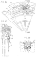
- Figures 20 to 26 represent a variant of a wear take-up device; sure these figures, we recognize a clutch having a plate pressure 51, a cover 52, a diaphragm 53, provided with an appendage actuator 55, articulated on the cover 52 by means of balusters 58 wearing a rolled crown offering secondary support to the diaphragm 53; the ramp means 54 include ramps 56 which cooperate with studs 57 of the pressure plate and a toothing 59 cooperates with an endless screw 63 which in turn is integral with rotation a ratchet wheel 60, having an axis 67 on which is wound a spring 86.
- the support 62 here metallic, is mounted radially above pressure plate 1.
- the support 62 is in the form of U, having a core 64 and two wings, 65 and 66, each carrying a hole 61 adapted to receive the axis 67 of the device; soul 64 door laterally a leg 68 at the square directed outwards intended to be fixed to the outer rim of the cover 52 by a rivet.
- the cover 52 has an opening for passage of the core 64 and is simplified.
- the wings 65 and 66 of the support 62 have, on the side opposite to the one where leg 68 is located, an axial extension of which the end is folded outwards to form a tab fixing 69 parallel to the tab 68 above and intended to be fixed to the bottom of the cover 52 by a rivet 70; on their edge directed towards the core 64, said extensions are provided with returns 71 directed towards each other, extending generally parallel to the core 64 and intended to constitute control stops, the role will appear below; the ends facing each other of said returns 71 are at a sufficient distance from each other to allow, without interfering, the movement of the actuator 55 during clutch and declutching operations.
- the elastic member 72 is in the shape of a jumper and comprises an elongated plane body 73 bearing each of its ends an arm 74 provided with a hole 75 adapted to receive axis 67; the two arms 74 are parallel, and extend on the same side and generally perpendicular to the body 73.
- the body 73 extends in an oblique extension 84 on the same side as that where are placed arms 74; notches 82 and 83 formed in the body 73 limit the extension 84 relative to the ends of the body 73 carrying arms 74; moreover, these notches 82 and 83 give extension 84 a certain elasticity.
- extension 84 The free end of extension 84 is provided with a return 85 which extends along a control tab 76 extending in direction of the body 73 while being generally parallel thereto.
- a cutout 77 is provided in the extension 84; in the favor of this cutout 77, and notches 79, 80 and 81 in the body 73, is made a non-return pawl 78 composed of two blades 78A and 78B; the free ends thereof extend generally perpendicular to body 73 and are slightly longer in length different; the difference in these lengths is such that when the blades 78A, 78B are in elastic support on the ratchet wheel 60, they are offset parallel to the arms 74 by a quantity less than the length of a tooth of the ratchet wheel 60: thus, the efficiency of the non-return function is improved by compared to the solution where the ratchet wheel only cooperates with a single non-return blade.
- Figures 27 to 33 show another variant; on these figures, the parts identical to those of the previous variant have the same references as these and will therefore not be described.
- the non-return functions, on the one hand, and control of the ratchet wheel 60, on the other hand, are not insured by the same piece as in the previous variants.
- the elastic member comprises two separate parts; a first part, for the non-return function, is a yoke 93, here metallic thinner than support 92, better visible in FIG. 31, in the shape of a U, the two wings 94 of which bear holes 95 to support the axis 67; the soul 96 of this stirrup is, on one of its sides, near its middle part, cut into blades 98 A to D which extend in a direction parallel to that wings 94 and extend along directed angled returns on the same side as the wings 94 relative to the core 96 overall perpendicular to said core 96; said returns have successively slightly increasing lengths; blades 98A-D constitute a non-return pawl 98 intended to cooperate with the ratchet wheel 60.
- the four 98A-D blades allow, compared to the previous version with two blades, an even larger one effectiveness of the non-return function.
- the support 92 better visible in FIG. 30, includes wings 115 and 116, which carry the legs 69 and are provided on their edge opposite the core 64 of notches 117 open on the side of the holes 61 for axis 67; these notches 117 make a slight angle with the plane of the core 64 and have a width adapted to receive the pivots 104 of the axis 103 of the control finger 101.
- said torque applies finger 101 on the teeth of the ratchet wheel 63 while the appendix actuator 55 of diaphragm 53, when the clutch is engaged, FIG. 28, bearing on the sleeve 102 which carries the finger 101, push it in the bottom of the tooth and spin the ratchet wheel 60 during wear; during a clutch release, the actuator appendage 55 approaches the bottom of the cover 52 by releasing the finger 101 which, recalled by an axial component of the effort of the filiform spring 107, follows the diaphragm while going up along the tooth concerned immobilized by the non-return pawl 98; in this movement of back, the finger 101 and its axis 103 follow the diaphragm 53 then leave the latter when the pivots 104 of said axis 103 abut in the bottom of the notches 117 of the support 92 forming a stop for control.
- Figures 34 to 38 show another clutch variant according to the invention which presents some differences compared to the previous variant.
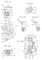
- the pressure plate 51 presents towards its periphery external a recess 120 facing the cover and allowing to accommodate the backlash device closer to the axis of the clutch, which simplifies the cover 52; moreover, this allows actuation of the control finger 121 described below directly through the outer periphery of the diaphragm 53: this avoids to provide the latter with an actuator appendage and therefore facilitates its manufacturing; to do this, the control finger 121, FIG. 38, is the tapered end of a hammerhead-shaped member 122 the heel of which has an edge 123 with which the outer periphery of the diaphragm 53.
- the free strands 109, 110 of the filiform spring 107 do not have no handles, such as handles 111, 112 of the variant previous, and the terminal segments 113, 114 are supported on the edge 124 provided inclined from the core 64 of the support 92.
- the non-return pawl 98 has only two blades, 98A and 98B.
- a mechanism friction clutch in particular for a motor vehicle, which includes a pressure plate 201 intended to cooperate with a friction disc not shown, bearing at its outer periphery friction linings, which itself cooperates with a plate of reaction.
- the reaction plate not shown, is intended to be stalled in rotation on a driving shaft, such as the crankshaft of the internal combustion engine.
- the friction disc is integral in rotation of a driven shaft such as the input shaft of the gearbox speeds.
- the pressure plate 201 is integral in rotation with a cover 202 of hollow form by means of tabs tangential 209 which, elastic, constitute at the same time means for returning the pressure plate 201 to the cover 202.
- the pressure plate 201 while being integral in rotation of the cover 202, is therefore axially displaceable relative to the cover 202 under the action of elastic action means axial controlled, here a diaphragm 203 resting on the cover 202 by its external periphery, the clutch here being of the pulled type, the declutching operation being carried out by acting on the tips of the diaphragm fingers in the direction of arrow F of Figure 40.
- a wear take-up device which comprises ramp means 211 arranged circumferentially; more precisely, these ramp means 211, FIGS. 40 and 41, are metallic by being obtained by stamping and made up of a ring with ramps 215 arranged circumferentially on its face facing the pressure plate 201; on his face opposite, said ring has a support zone 214 constituted by a rounded upper edge arranged in an arc centered on the clutch axis.
- said support zone 214 can be continuous or discontinuous.
- the pressure plate 201 has, on its face facing the bottom of cover 202, studs 204 from here molding distributed circumferentially at a distance from each other which corresponds to the one that circumferentially separates two ramps 215 successive, the studs 204 being intended to cooperate each with a ramp 215.
- the ramp means 211 are placed axially between the diaphragm 203 and the pressure plate 201 so that the studs 204 receive the ramps 215 and the diaphragm 203 cooperates with the support zone 214 which thus constitutes the support means by through which the diaphragm 203 acts on the plate of pressure 201.
- the internal periphery of the ramp means 211 is provided radially of a toothing 218.
- the wear take-up device also comprises a ratchet wheel 220 with inclined teeth 221 rotatably mounted around a axis 222 which also carries an endless screw 213; the net and the pitch of the worm gear 213 are adapted to the teeth 218 of the means with ramps 211; the worm 213 is brought to cooperate with the toothing 218 under the conditions which will be described below.
- teeth 221 are cut at the outer periphery of the worm screw thread 213. This arrangement, better visible on Figures 42 and 43 is economical and simple.
- the axis 222 is carried in rotation by a support 212, better visible in FIGS. 41 and 42, in cut and folded sheet metal, shaped general of L having two wings 223, 224 of which one, 223, is intended to support the axis 222 and of which the other, 224, is intended to fixing the support 212 on the cover 202; for this purpose, wing 223 carries a circular hole 225 adapted to receive the end of the axis 222, here threaded to receive a nut fixation. According to a variant. not shown, wing 223 is provided of a thread which receives the threaded end of the axis 222, this to remove the nut.
- the wing 224 is fixed to the bottom of the cover 202 while the wing 223 crosses the diaphragm 203 between two of his fingers which, if necessary, can be circumferentially spread more than are two by two the other fingers.
- the support 212 is adapted to receive an elastic member 272, here metallic and thinner than the support, better visible in Figure 44;
- the elastic member 272 is shaped general rider and includes a flat body 273 bearing each from its ends an arm 274 provided with a hole 275 adapted to receive axis 222; the two arms 274 are parallel and extend the same side and generally perpendicular to the body 273.
- the body 273 extends, between the arms 274, according to an extension 284 which includes a first part 284A in the extension of the body 273, a second part 284B directed in the opposite direction to that of the arms 274 making a acute angle with the body 273, a third part 284C forming a U with the second part 284B and extending parallel thereto, and a fourth part 284D directed towards the body 273 while being parallel to it, at a slightly higher level so that it extends between the arms 274; this fourth part 284D receives, for example by riveting, a T-shaped plate of which the foot 235 constitutes a control tab 235; both arms of the T each pass through a notch 274A formed in each of the arm 274 so that the stroke of the control tongue 235, parallel to the body 273, is limited, at least away from the body 273; on its longitudinal edge opposite to that where it is located extension 284, body 273 carries a non-return pawl 236 here consisting
- the arm 274, of the elastic member 272, bearing on the wing 223 of the support 212, has a hole 253, FIG. 44, intended to cooperate with a stud 254, FIG. 42, provided on the internal face of said wing 223 for angular positioning of the elastic member 272 relative to to support 212.
- the stud 254 can be replaced by a pin or any other protuberance.
- the axis 222 carries a flange 244 near its end unthreaded; around the axis 222 is placed a helical spring 240 constituting the elastic take-up means, as described below ; here, the spring 240 is wound around the axis 222 in being placed in a housing 251 provided inside the wheel to ratchet 220 (or worm gear 213); ratchet wheel 220 (or screw without end 213) is centered with respect to axis 222, on one side, bearing on the flange 244 of said axis and, on the other side, by means of a redent circular interior 252 it presents; spring 240 is thus placed axially between said redent 252 and the flange 244 of axis 222; ratchet wheel 220 is to the right of the ratchet non-return 236 which, by cooperation with the inclined teeth 221 of ratchet wheel 220, prevents turning ratchet wheel 220, so the worm screw 213, counterclockwise of
- the wear take-up device which has just been described works as follows, knowing that the tooth system 218 - screw without end 213 is irreversible, screw 213 can cause toothing 218 and not the reverse.
- Figure 40 shows the clutch engaged, the linings of the friction disc being in new condition and clamped between the plate of reaction, not shown, and the pressure plate 201.
- the control tab 235 and the non-return pawl 236 have their end at the foot of a ratchet wheel tooth 220.
- the pressure 201 When the linings wear out, as we know, the pressure 201, always subjected to the axial force of the diaphragm 203, is brings it closer to the reaction plate which is axially fixed like the cover 202; the finger 250 of the diaphragm 203 therefore approaches the reaction plate, therefore from the open end of the cover 202, by driving in its movement the control tab 235; the ratchet wheel 220 rotates around its axis clockwise, direction in which the non-return pawl 236 does not perform its function but can jump from tooth to tooth; this rotating drive of the ratchet wheel 220 drives the worm gear 213 to turn also on its axis; the ramp means 211 being immobilized relative to cover 203 under the effect of the diaphragm load 203, the worm gear 213 which meshes with the toothing 218 of the means of ramps 211 is sort of screwed onto this toothing 218 in compressing the coil spring 240, the direction of the thread of the screw endless
- the pressure plate 201 releases the toppings moving away from them under the action of the tabs tangentials 209 which bring back towards the bottom of the cover 202 the pressure plate 201 as well as the ramp means 211 in contact with the diaphragm 203 by their support zones 214 and with the studs 204 of the pressure plate 201 by their ramps 215.
- the spring helical 240 urges the worm gear 213 towards the wing 223 of the support 212, from which it has moved away in wear phases, that is to say from right to left with respect to Figures 41 and 42; the load of the diaphragm 203 no longer being applied to the means to ramps 211, the only effort to overcome in order to rotate these ramp means 211 relative to the pressure plate 201 is the return force of the tangential tabs 209; if the charge helical spring 240 is sufficient to overcome this effort, then the spring 240 moves the worm 213 which is prevented from turn on itself by pressing the non-return pawl 236 and which will cause the teeth 218: by turning on themselves, the ramps 215 of the ramp means 211, by cooperation with the studs 204 from pressure plate 201, move pressure plate away 201 from the bottom of the cover 202, thereby increasing the axial distance between the working face of the pressure plate 201 and the zones of support 214 of the ramp means 211, thus catching up at least in
- Spring load helical 240 being a function of the quantity of which it will have been compressed by the worm screw 213 during the wear phases, we see that several clutch and disengage operations can be necessary before the backlash device comes into operation catch-up phase proper, this being a function of the relative dimensioning of the parts concerned; for example, these can be performed so that this phase of catch-up proper only occurs the first time after wear corresponding to three tenths of a millimeter.
- the ratchet wheel 220 If the wear has been sufficient for the ratchet wheel 220 to have turned enough so that on return the tongue 235 jumps a tooth, during the clutch operation, the tongue 235, pushed by finger 250, turns ratchet wheel 220 and the means to ramps 211, not yet tightened by the diaphragm 203, rotate and catch up on wear; at the end of the catch-up operation, the diaphragm, ratchet wheel 220, non-return pawl 236 and control tab 235 return to their position they occupied in Figure 40.
- the worm 213 and the ratchet wheel 220 being cut in the same part, as can be seen, the support 212 equipped with this same part, of the elastic member 272, of the spring 240 and of the axis 222 constitutes a sub-assembly ready to be installed on the cover 202.
- the spring 240 is wrapped around the axis 222 while being housed inside the room single compact axially forming ratchet wheel 220 and worm 213; according to the variant of FIG. 45, the spring is at the exterior of said single piece being produced in the form of a elastic stirrup 340 straddling said single piece.
- the axis 222 is inclined, with respect to a plane perpendicular to the axis of the clutch, at an angle equal to that of the worm screw thread 213 ; thanks to this arrangement, the teeth constituting the toothing 218 are straight teeth, which facilitates the manufacture of the means to ramps 214.
- the pressure plate 201 releases the linings away from them under the action of tangential tabs 209 which bring towards the bottom of the cover 202 the pressure plate 201 and the ramp means 211; for be sure that the coil spring 240 can actuate the means to ramps 211 without being hampered by the axial return force due to tangential tabs 209, it may be advantageous to limit the pressure plate travel 201 during declutching operations.
- the variant of Figure 48 shows a layout on allowing; according to this variant, the pressure plate 201 carries an axial pin 301, which may for example be an extension of a rivet for fixing the tabs 209 to the plate 201; pawn 301 carries two flanges 302, 303 defining axial stops.
- axial pin 301 which may for example be an extension of a rivet for fixing the tabs 209 to the plate 201
- pawn 301 carries two flanges 302, 303 defining axial stops.
- a ring 305 surrounds the pin 301 and its axial length is less than the length which axially separates the two flanges 302 and 303, the difference in said lengths defining a clearance axial.
- the ring 305 is fitted into a hole in the edge of the cover 202 of which it is secured by friction, the axial stops 302 and 303 being arranged on either side of said edge; said axial clearance thus defines the return stroke of the plate 201 by the tabs 209; this axial play is constant whatever the wear of the fittings; indeed, in the event of wear of these, the ring 305 is displaced by the force of the diaphragm which is greater than the force of friction between the ring 305 and the cover 202, which force being greater than the axial force due to the tongues 209.
- the non-return means are constituted by a pawl which cooperates with the ratchet wheel; alternatively, this are friction means, like friction pads by example.
- Preferably only one wear take-up device is planned.
- the wear take-up device is not very sensitive to vibrations, especially those due to axial vibrations of the vehicle engine crankshaft due to screw action end on a toothing integral with the ramp means.
- the wear take-up device is not very sensitive to the effects centrifugal force and thermal deformation.
- the ratchet wheel - worm gear - coil spring assembly is space-saving and does not obstruct the ventilation of the clutch. This ventilation is favored by the presence of openings in the means with ramps, as well as by the presence of studs.
- Elastic means with axial action may have another shape as described for example in FR-A-2 753 758, FR-A-2 753 756, FR-A-2 761 738 and FR-A- 2 761 739.
- the Belleville washer is a type assistance washer positive.
- This assistance washer is for example dimensioned in function of the means of progressiveness mounted within the disc of friction.
- the assistance washer can be mounted in parallel with the diaphragm, for example by acting between the cover and the inner end of the diaphragm fingers, such as described in document FR-A 2,728,638.
Description
La présente invention concerne un embrayage à friction, notamment pour véhicule automobile, et se rapporte plus particulièrement à un embrayage équipé d'un dispositif de compensation de l'usure due notamment à l'usure des garnitures de friction, ledit dispositif, dit ci-après dispositif de rattrapage d'usure, opérant au fur et à mesure de l'usure desdites garnitures.The present invention relates to a friction clutch, especially for a motor vehicle, and relates more particularly to a clutch fitted with a compensation of wear due in particular to the wear of the linings of friction, said device, hereinafter referred to as a take-up device wear, operating as and when said linings wear.
Un embrayage à friction classique comporte généralement un plateau de réaction, éventuellement en deux parties pour formation d'un volant amortisseur, calé en rotation sur un premier arbre, usuellement un arbre menant tel que le vilebrequin du moteur à combustion interne, et supportant par sa périphérie externe un couvercle auquel est rattaché au moins un plateau de pression.A conventional friction clutch usually has a reaction plate, possibly in two parts for training a damping flywheel, set in rotation on a first shaft, usually a driving shaft such as the crankshaft of the engine internal combustion, and supporting by its external periphery a cover to which at least one pressure plate is attached.
Le plateau de pression est solidaire en rotation du couvercle et du plateau de réaction tout en pouvant se déplacer axialement sous la sollicitation de moyens élastiques à action axiale commandés, généralement un diaphragme métallique prenant appui sur le couvercle, tandis qu'un disque de friction, portant des garnitures de friction à sa périphérie externe, solidaire en rotation d'un arbre, usuellement un arbre mené tel que l'arbre d'entrée de la boíte de vitesses, est intercalé entre le plateau de pression et le plateau de réaction de façon à être serré entre eux lorsque l'embrayage est en position d'engagement. Le diaphragme commande le déplacement axial du plateau de pression lorsqu'il est actionné par une butée de débrayage. Plus précisément la partie périphérique du diaphragme forme les moyens élastiques précités ou moyens embrayeurs commandés par des moyens débrayeurs, ici les doigts du diaphragme. Les moyens débrayeurs permettent, lorsqu'ils sont actionnés par la butée de débrayage, de contrecarrer l'action des moyens débrayeurs.The pressure plate is integral in rotation with the cover and of the reaction plate while being able to move axially under the use of elastic means with controlled axial action, usually a metal diaphragm resting on the cover, while a friction disc, bearing linings friction at its outer periphery, integral in rotation with a tree, usually a driven tree such as the input shaft of the gearbox, is interposed between the pressure plate and the reaction plate so as to be clamped together when the clutch is in the engagement position. The diaphragm controls the axial displacement of the pressure plate when actuated by a clutch release bearing. More precisely the peripheral part of the diaphragm forms the above-mentioned elastic means or engagement means controlled by declutching means, here the fingers of the diaphragm. The declutching means allow, when actuated by the clutch release bearing, to counteract the action of the declutching means.
Au cours de la durée de vie d'un tel embrayage, les garnitures de friction ainsi que les contre-matériaux, plateau de pression et plateau de réaction, s'usent, ce qui provoque une variation de la position du plateau de pression et celles des moyens élastiques à action axiale et de la butée de débrayage, d'où il s'ensuit une variation de la force de serrage entre le disque de friction, d'une part, et les plateaux de pression et de réaction, d'autre part, en raison des modifications des conditions de travail du diaphragme, et la force nécessaire pour débrayer s'en trouve affectée. En dotant un tel embrayage d'un dispositif de rattrapage d'usure, on évite ces inconvénients, le diaphragme, ainsi que la butée de débrayage, usuellement en appui constant sur le diaphragme, occupant la même position lorsque l'embrayage est en position d'engagement.During the service life of such a clutch, the linings friction as well as the counter materials, pressure plate and reaction plate, wear out, causing a variation in the position of the pressure plate and those of the elastic means to axial action and the clutch release bearing, from which a variation of the clamping force between the friction disc, by part, and the pressure and reaction plates, on the other hand, due to changes in working conditions of the diaphragm, and the force necessary to disengage is affected. By providing a such clutch of a wear take-up device, these disadvantages, the diaphragm, as well as the clutch release bearing, usually in constant support on the diaphragm, occupying the same position when the clutch is in the engagement position.
On a déjà proposé, selon le document US-A-5 090 536, de réaliser un dispositif de rattrapage en disposant entre le diaphragme et le plateau de pression deux bagues annulaires portant des rampes complémentaires, une première bague annulaire étant fixe en rotation par rapport au plateau de pression, la seconde étant déplaçable en rotation, par rapport à celui-ci et à la première, le déplacement relatif circonférentiel des deux bagues conduisant, du fait des rampes complémentaires qu'elles portent, à un écartement des bagues dans le sens axial compensant ladite usure, cet écartement simulant une augmentation de l'épaisseur axiale du plateau de pression ; pour son déplacement relatif en rotation, la seconde bague est munie à sa périphérie d'un secteur denté dont les dents engrènent avec une vis sans fin disposée de manière tangentielle et montée à rotation sur un axe porté par le couvercle de l'embrayage ; la vis sans fin est susceptible d'être entraínée en rotation, par l'intermédiaire d'un accouplement unidirectionnel, par un tambour porté par le même axe qui porte la vis sans fin, lequel tambour est, en cas d'usure des garnitures du disque de friction, entraíné lui-même en rotation ; l'accouplement unidirectionnel est disposé en sorte que la vis sans fin est entraínée par le tambour, qui constitue en quelque sorte une pièce d'armement du dispositif, lorsque celui-ci est lui-même entraíné en rotation lors du débrayage, la rotation de la vis sans fin conduisant à une rotation de la seconde bague, comme cela a été dit ci-dessus.It has already been proposed, according to document US-A-5,090,536, to carry out a catch-up device by placing between the diaphragm and the pressure plate two annular rings carrying ramps complementary, a first annular ring being fixed in rotation relative to the pressure plate, the second being movable in rotation, with respect to this and to the first, the displacement circumferential relative of the two conducting rings, due to the additional ramps they carry, at a spacing of the rings in the axial direction compensating for said wear, this spacing simulating an increase in the axial thickness of the pressure plate; for its relative displacement in rotation, the second ring is provided at its periphery of a toothed sector whose teeth mesh with a screw endless tangentially arranged and rotatably mounted on an axis carried by the clutch cover; the worm is likely to be rotated, via a unidirectional coupling, by a drum carried by the same axis which carries the worm, which drum is, in case of wear of the friction disc linings, itself rotated; the one-way coupling is arranged so that the screw without end is driven by the drum, which in a way constitutes a arming part of the device, when the device is itself rotated during disengagement, the rotation of the screw without end leading to a rotation of the second ring, as has been said above.
Un accouplement unidirectionnel disposé entre la vis sans fin et l'axe qui la supporte permet à celle-ci de conserver sa position en rotation après chaque réglage.A one-way coupling arranged between the worm and the axis that supports it allows it to maintain its position in rotation after each adjustment.
Un tel dispositif, selon le document US-A-5 090 536, présente les inconvénients suivants : la pièce d'armement, qui est portée par le couvercle de l'embrayage, est susceptible d'être entraínée en rotation par un levier lui-même commandé par la butée de débrayage ; dès lors, la butée de débrayage doit être spécifiquement adaptée à la commande dudit levier et est encombrante axialement ; par ailleurs, lorsque la butée de débrayage est amenée à être déplacée axialement au delà de la course juste nécessaire pour l'opération de débrayage, l'opération de rattrapage est effectuée alors qu'il n'y a pas eu usure, ce qui est dangereux car pouvant conduire à un blocage de l'embrayage qui finit par ne plus pouvoir être débrayé.Such a device, according to document US-A-5,090,536, has the following disadvantages: the armament, which is carried by the clutch cover is likely to be driven in rotation by a lever itself controlled by the release bearing; therefore, the clutch release bearing must be specifically adapted to the control of said lever and is bulky axially; through elsewhere, when the clutch release bearing is caused to be moved axially beyond the stroke just necessary for the operation of declutching, the catch-up operation is carried out when there is no no wear, which is dangerous because it can lead to blockage of the clutch which ends up being unable to be disengaged.
Il est connu du document FR-A-2 424 442, conforme au préambule
de la revendication 1, un embrayage à friction, comportant un
plateau de réaction destiné à être calé en rotation sur un arbre
menant, un disque de friction, portant à sa périphérie externe des
garnitures de friction, destiné à être calé en rotation sur un arbre
mené, un plateau de pression, un couvercle
fixé sur le plateau de réaction, des moyens-élastiques à action
axiale agissant entre, d'une part, le couvercle
et, d'autre part, le plateau de pression par
l'intermédiaire de moyens d'appui, le plateau de pression
étant solidaire en rotation du couvercle
tout en pouvant se déplacer axialement par rapport à lui et étant
soumis à l'action de moyens élastiques de rappel rappelant
le plateau de pression axialement vers le couvercle,
ledit embrayage comportant également un dispositif de
rattrapage d'usure comprenant des moyens à rampes
disposées circonférentiellement, placés axialement entre les moyens
d'appui et le plateau de pression et adaptés
à être entraínés en rotation grâce à une denture
qu'ils portent à leur périphérie et avec laquelle coopère une vis
sans fin disposée tangentiellement, des moyens
d'entraínement en rotation de la vis sans fin
étant prévus, rendus opérationnels par l'usure des garnitures
de friction lorsque l'embrayage est embrayé, ainsi que des moyens
anti-retour empêchant la vis sans fin
de tourner dans le sens contraire de celui dans lequel elle est
entraínée en rotation par les moyens d'entraínement en rotation
lorsqu'ils sont opérationnels, la vis sans fin,
les moyens anti-retour et les moyens
d'entraínement en rotation de la vis sans fin
étant portés par un support solidaire du
couvercle, et les moyens élastiques à action axiale
étant constitués par un diaphragme, qui commande la
rotation de la vis sans fin par l'intermédiaire d'une
pièce de commande appartenant aux dits
moyens d'entraínement en rotation de la vis sans fin.It is known from document FR-A-2 424 442, in accordance with the preamble
of
La présente invention a pour but de pallier ces inconvénients.The present invention aims to overcome these drawbacks.
Ce but est atteint grâce au fait que la course de la pièce de commande lors de l'opération de débrayage est limitée par une butée dite de contrôle. This goal is achieved by the fact that the stroke of the workpiece control during the clutch release operation is limited by a so-called control stop.
Le fait que la vis sans fin, les moyens anti-retour et les moyens d'entraínement en rotation de la vis sans fin sont portés par le couvercle améliore la précision de la détection de l'usure.The fact that the worm, the non-return means and the means for driving the worm in rotation are carried by the cover improves the accuracy of wear detection.
Avantageusement, les moyens d'entraínement en rotation, de la vis sans fin, sont commandés par le diaphragme par l'intermédiaire d'une languette ou doigt de commande, formant pièce de commande, dont la course, lors de l'opération de débrayage, est limitée par une butée dite de contrôle.Advantageously, the rotation drive means, the augers, are controlled by the diaphragm via an operating tab or finger, forming an operating part, whose stroke, during the declutching operation, is limited by a so-called control stop.
Avantageusement, les moyens à rampes sont constitués d'un anneau présentant des rampes inclinées et réparties circonférentiellement ; de préférence, le plateau de pression présente des plots ou des rampes destinés à coopérer avec les rampes des moyens à rampes.Advantageously, the ramp means consist of a ring having inclined and circumferentially distributed ramps; preferably, the pressure plate has studs or ramps intended to cooperate with the ramps of the ramp means.
Avantageusement, ledit anneau présente également des zones d'appui constituées par l'arête supérieure arrondie d'emboutis disposés en arcs de cercle centrés sur l'axe de l'embrayage et placés radialement à l'extérieur par rapport aux rampes ; grâce à cette disposition, d'une part, les zones d'appui sont de grande longueur et, d'autre part, les rampes peuvent être nombreuses ainsi, les pressions de contact sont minimisées.Advantageously, said ring also has zones of support constituted by the rounded upper edge of stampings arranged in circular arcs centered on the axis of the clutch and placed radially outside relative to the ramps; thanks to this arrangement, on the one hand, the support zones are large length and, on the other hand, the ramps can be numerous as well, contact pressures are minimized.
De préférence, les moyens à rampes présentent un rebord axial muni d'ouvertures de ventilation ; avantageusement, les moyens à rampes présentent un rebord axial centrant les moyens à rampes par rapport au plateau de pression.Preferably, the ramp means have an axial rim provided with ventilation openings; advantageously, the means to ramps have an axial rim centering the ramp means by compared to the pressure plate.
Avantageusement, la vis sans fin est montée à coulissement selon son axe en étant soumise à l'action d'un moyen élastique dit de rattrapage et, lorsqu'elle est déplacée selon son axe, elle entraíne en rotation circonférentielle lesdits moyens à rampes ; de préférence, la charge du moyen élastique de rattrapage croít avec l'usure des garnitures de friction et ledit déplacement axial est obtenu par action du moyen élastique de rattrapage lorsque sa charge est suffisamment élevée pour surmonter l'effort de frottement dû à l'effort axial provenant des moyens élastiques de rappel auxquels sont soumis lesdits moyens à rampes, l'embrayage étant débrayé ; en variante, la course du plateau de pression est limitée dans le sens du débrayage pour libérer les moyens à rampes de l'effort axial provenant des moyens élastiques de rappel.Advantageously, the worm is slidably mounted according to its axis being subjected to the action of an elastic means called catching up and, when it is moved along its axis, it drives in circumferential rotation said ramp means; of preferably, the load of the elastic take-up means increases with the wear of the friction linings and said axial displacement is obtained by action of the elastic catch-up means when its load is high enough to overcome the friction force caused by the axial force coming from the elastic return means to which said ramp means are subjected, the clutch being disengaged; in variant, the pressure plate stroke is limited in the direction release to release the ramp means from the axial force from elastic return means.
Avantageusement, le moyen élastique de rattrapage est un ressort hélicoïdal entourant un axe qui porte la vis sans fin ; les moyens d'entraínement en rotation de la vis sans fin sont constitués par une roue à rochet solidaire de la vis sans fin.Advantageously, the elastic take-up means is a spring helical surrounding an axis which carries the worm; ways drive in rotation of the worm are constituted by a ratchet wheel secured to the worm.
De préférence, l'axe portant la vis sans fin et le ressort hélicoïdal est supporté par le support.Preferably, the axis carrying the worm and the spring helical is supported by the support.
Avantageusement, les moyens anti-retour sont constitués par un cliquet qui coopère avec la roue à rochet.Advantageously, the non-return means are constituted by a ratchet which cooperates with the ratchet wheel.
L'embrayage peut être du type poussé, le diaphragme étant solidarisé au couvercle par des colonnettes ; il peut également être du type tiré.The clutch can be of the pushed type, the diaphragm being secured to the cover by balusters; it can also be of the type drawn.
Le support est en forme de U ayant une âme et deux ailes destinées à supporter l'axe ; les ailes du support se prolongent selon des bras en forme de L s'étendant l'un vers l'autre perpendiculairement à l'âme et se terminant chacun par une extrémité en forme de C sertie sur le bord d'une ouverture transversale du couvercle ; cette ouverture est prévue dans une excroissance radiale définissant un logement pour le dispositif de rattrapage de jeu.The support is U-shaped with a core and two wings intended to support the axis; support wings extend in L-shaped arms extending towards each other perpendicular to the core and each ending in one end C-shaped set on the edge of a transverse opening of the cover; this opening is provided in a radial projection defining a housing for the game take-up device.
Le support est adapté à recevoir un organe élastique, en forme générale de crosse dont chaque extrémité est munie d'un retour vers l'intérieur ; la partie de plus grande longueur de la crosse croit en largeur vers son extrémité se terminant selon un retour qui porte en bout une languette de commande ; la partie de plus petite longueur de la crosse a son retour formant cliquet anti-retour qui s'étend globalement parallèlement à la languette de commande en étant à distance de celle-ci en sorte que, lorsque l'organe élastique et la roue à rochet sont montés dans le support, le cliquet anti-retour et la languette de commande coopèrent chacun avec un pied de dent ; pour son montage dans le support, l'organe élastique porte latéralement des bras en équerre disposés de part et d'autre de la partie élastique en forme de crosse, orthogonalement par rapport à celle-ci, et l'extrémité libre des bras en équerre porte des trous pour l'axe.The support is adapted to receive an elastic, shaped member butt stock, each end of which has a return to the interior; the longer part of the butt believes in width towards its end ending in a return which carries at the end a control tab; the smallest part length of the stock at its return forming a non-return pawl which generally extends parallel to the control tab in being at a distance from it so that when the organ elastic and the ratchet wheel are mounted in the support, the non-return pawl and control tab each cooperate with a tooth foot; for its mounting in the support, the organ elastic sideways carries angled arms arranged on both sides and other of the elastic part in the form of a butt, orthogonally relative to it, and the free end of the arms angled carries holes for the axis.
Avantageusement, la vis sans fin et la roue à rochet sont taillées dans une même pièce de réalisation simple et économique.Advantageously, the worm and the ratchet wheel are cut in a single piece of simple and economical production.
Le support équipé de la vis sans fin, de la roue à rochet, de l'organe élastique, du ressort et de l'axe constitue un sous-ensemble prêt à être installé dans le couvercle.The support equipped with the worm, the ratchet wheel, the elastic member, of the spring and of the axis constitutes a subset ready to install in the cover.
Le diaphragme porte à sa périphérie un appendice radial dit actionneur s'étendant radialement à l'extérieur de la partie rondelle Belleville du diaphragme pour coopérer avec la zone élargie de la partie de grande longueur de l'organe élastique.The diaphragm carries at its periphery a radial appendage called actuator extending radially outside the part Belleville washer of the diaphragm to cooperate with the enlarged area of the very long part of the elastic member.
Les dents de la roue à rochet sont réalisées en sorte que, lors de la course de débrayage garnitures de friction neuves, l'extrémité de la languette de commande ne saute pas une dent, avantageusement le cliquet anti-retour maintenant la roue à rochet.The teeth of the ratchet wheel are made so that when of the clutch release race new friction linings, the end of the control tongue does not skip a tooth, advantageously the non-return pawl holding the ratchet wheel.
Les dents de la roue à rochet sont réalisées en sorte que, lors d'une course de débrayage minimum définie par construction, et abstraction faite de la butée de contrôle, l'extrémité de la languette de commande saute une dent.The teeth of the ratchet wheel are made so that when a minimum declutching stroke defined by construction, and apart from the control stop, the end of the control tab jumps a tooth.
La partie de grande longueur de la crosse de l'organe élastique vient en butée contre les bras du support.The long part of the butt of the elastic member abuts against the arms of the support.
Si l'usure a été suffisante pour que la roue à rochet ait suffisamment tourné de sorte qu'au retour la languette de commande a sauté une dent, la languette de commande, poussée par l'actionneur, fait tourner, lors de l'opération d'embrayage, la roue à rochet et les moyens à rampes.If the wear has been sufficient for the ratchet wheel to have turned enough so that on return the control tab has jumped a tooth, the control tab, pushed by the actuator, rotates, during the clutch operation, the ratchet wheel and ramp means.
De préférence, le support est en forme de U, ayant une âme et deux ailes, chacune portant un trou adapté à recevoir l'axe du dispositif, l'âme portant latéralement une patte à l'équerre dirigée vers l'extérieur destinée à être fixée sur le rebord externe du couvercle ; les ailes du support présentent, du côté opposé à celui où est située la patte, un prolongement axial dont l'extrémité est pliée vers l'extérieur pour constituer une patte de fixation parallèle à la patte ci-dessus et destinée à être fixée au fond du couvercle ; sur leur tranche dirigée vers l'âme, lesdits prolongements sont munis de retours dirigés l'un vers l'autre en s'étendant globalement parallèlement à l'âme et destinés à constituer des butées ; les extrémités se faisant face desdits retours sont à une distance suffisante l'une de l'autre pour permettre, sans le gêner, le débattement de l'actionneur lors des opérations d'embrayage et de débrayage.Preferably, the support is U-shaped, having a core and two wings, each carrying a hole adapted to receive the axis of the device, the soul carrying laterally a lug with a directed square outwardly intended to be fixed on the outer edge of the cover; the wings of the support have, on the side opposite to that where the tab is located, an axial extension whose end is folded outwards to form a mounting bracket parallel to the leg above and intended to be fixed to the bottom of the cover; on their edge facing the soul, said extensions are provided with returns directed towards each other in extending generally parallel to the core and intended for constitute stops; the ends facing each other of said returns are at a sufficient distance from each other to allow, without interfering, the movement of the actuator during clutch and declutching operations.
L'organe élastique est en forme de cavalier et comprend un corps plan allongé portant à chacune de ses extrémités un bras muni d'un trou adapté à recevoir l'axe ; sur l'un de ses bords longitudinaux, le corps se prolonge selon une extension en oblique du même côté que celui où sont placés les bras ; des échancrures ménagées dans le corps limitent l'extension par rapport aux extrémités du corps portant les bras ; l'extrémité libre de l'extension est munie d'un retour qui se prolonge selon une languette de commande s'étendant en direction du corps en étant globalement parallèle à celui-ci ; une découpe est ménagée dans l'extension ; à la faveur de cette découpe, et d'échancrures dans le corps, est réalisé un cliquet anti-retour composé d'au moins deux lames de longueurs légèrement différentes.The elastic member is in the form of a jumper and includes a body elongated plane carrying at each of its ends an arm provided with a hole adapted to receive the axis; on one of its longitudinal edges, body extends obliquely on the same side as the one where the arms are placed; notches in the body limit extension relative to body ends carrying arms; the free end of the extension is provided with a return which extends along a control tab extending in direction of the body being generally parallel to it; a cut-out is provided in the extension; thanks to this cut, and notches in the body, a non-return ratchet is produced composed of at least two blades of slightly different lengths.
En variante, l'organe élastique comprend deux pièces distinctes ; une première pièce, pour la fonction anti-retour, est un étrier en forme de U dont les deux ailes portent des trous pour supporter l'axe ; l'âme de cet étrier est, sur l'un de ses côtés, au voisinage de sa partie médiane, découpée en au moins deux lames qui s'étendent dans une direction parallèle à celle des ailes et se prolongent selon des retours en équerre dirigés du même côté que les ailes par rapport à l'âme globalement perpendiculairement à ladite âme ; lesdits retours ont des longueurs légèrement différentes et les lames constituent un cliquet anti-retour destiné à coopérer avec la roue à rochet.As a variant, the elastic member comprises two separate parts ; a first part, for the non-return function, is a stirrup in U shape with two wings carrying holes to support the axis; the soul of this stirrup is, on one of its sides, in the vicinity of its middle part, cut into at least two blades which extend in a direction parallel to that of the wings and extend according to square returns directed on the same side as the wings by relative to the core generally perpendicular to said core; said returns have slightly different lengths and blades constitute a non-return pawl intended to cooperate with the ratchet wheel.
Avantageusement, la seconde pièce, pour la fonction commande de la roue à rochet, est un ressort filiforme, associé à un doigt porté par un manchon cylindrique emmanché sur un axe ; le manchon et son doigt sont solidarisés en rotation à l'arbre par une goupille traversant diamétralement le manchon et l'arbre en dépassant d'un côté du manchon pour réaliser un toc d'appui pour le fond d'une boucle ouverte d'un ressort filiforme conformé en une sorte de patère, ledit ressort filiforme étant adapté à soumettre le doigt de commande à un couple de torsion appliquant l'extrémité du doigt sur la roue à rochet.Advantageously, the second part, for the control function of the ratchet wheel, is a threadlike spring, associated with a worn finger by a cylindrical sleeve fitted on an axis; the sleeve and its finger are secured in rotation to the shaft by a pin passing diametrically through the sleeve and the shaft, protruding by one side of the sleeve to make a support for the bottom of a open loop of a threadlike spring shaped like a hook, said filiform spring being adapted to subject the finger control at a torque applying the tip of the finger to the ratchet wheel.
De préférence, le support comprend des ailes qui sont munies sur leur bord opposé à l'âme d'échancrures ouvertes du côté des trous pour l'axe, ces échancrures faisant un léger angle avec le plan de l'âme et ayant une largeur adaptée à recevoir l'axe du doigt de commande.Preferably, the support comprises wings which are provided on their edge opposite the core of open notches on the side of the holes for the axis, these notches making a slight angle with the plane of the core and having a width adapted to receive the axis of the finger of ordered.
Avantageusement, le plateau de pression présente vers sa périphérie externe un embrèvement faisant face au couvercle et permettant de loger le dispositif de rattrapage d'usure.Advantageously, the pressure plate presents towards its outer periphery a recess facing the cover and for housing the wear take-up device.
De préférence, le doigt de commande est directement actionné par la périphérie externe du diaphragme. Preferably, the control finger is directly actuated by the outer periphery of the diaphragm.
Avantageusement, les dents de la roue à rochet sont taillées à la périphérie externe du filet de la vis sans fin. Cette disposition est économique et simple ; la pièce est plus légère, moins complexe ; la roue à rochet peut ainsi comporter plus de dents ; l'encombrement axial est plus faible ; l'usinage est plus facile et la fiabilité est meilleure.Advantageously, the teeth of the ratchet wheel are cut to the outer periphery of the worm screw thread. This provision is economical and simple; the piece is lighter, less complex ; the ratchet wheel can thus have more teeth; the axial size is smaller; machining is easier and reliability is better.
De préférence, le support est en forme générale de L ayant deux ailes dont l'une est destinée à supporter l'axe et dont l'autre est destinée à la fixation du support sur le couvercle ; l'aile supportant l'axe traverse le diaphragme entre deux de ses doigts.Preferably, the support is in general L shape having two wings, one of which is intended to support the axis and the other of which is intended for fixing the support on the cover; the wing supporting the axis crosses the diaphragm between two of its fingers.
Avantageusement, l'organe élastique est en forme générale de cavalier et comprend un corps plan portant à chacune de ses extrémités un bras muni d'un trou adapté à recevoir l'axe ; les deux bras sont parallèles et s'étendent du même côté et globalement perpendiculairement par rapport au corps ; sur l'un de ses bords longitudinaux, le corps se prolonge selon une extension qui comprend une première partie dans le prolongement du corps, une deuxième partie dirigée dans le sens opposé à celui des bras en faisant un angle aigu avec le corps, une troisième partie formant un U avec la deuxième partie et s'étendant parallèlement à celle-ci, et une quatrième partie dirigée vers le corps en étant parallèle à celui-ci, à un niveau légèrement supérieur en sorte qu'elle s'étend entre les bras; cette quatrième partie constitue directement ou non une languette de commande ; une échancrure ménagée dans chacun des bras limite la course de la languette de commande, parallèlement au corps, au moins en éloignement du corps ; sur son bord longitudinal opposé à celui où se situe l'extension, le corps porte un cliquet anti-retour constitué d'au moins deux lames de longueurs différentes, la différence de ces longueurs étant de l'ordre d'une demi-dent.Advantageously, the elastic member is in the general form of rider and includes a flat body bearing at each of its ends an arm provided with a hole adapted to receive the axis; both arms are parallel and extend on the same side and overall perpendicular to the body; on one of its edges longitudinal, the body extends in an extension which includes a first part in the extension of the body, a second part directed in the opposite direction to that of the arms by making a acute angle with the body, a third part forming a U with the second part and extending parallel thereto, and a fourth part directed towards the body while being parallel to this one, at a slightly higher level so that it extends between arms; this fourth part directly or indirectly constitutes a control tab; a cutout in each of the arms limits the travel of the control tongue, parallel to the body, at least away from the body; on its longitudinal edge opposite to where the extension is located, the body carries a ratchet check valve made up of at least two length blades different, the difference of these lengths being of the order of one half tooth.
Avantageusement, le moyen élastique de rattrapage est un ressort enroulé autour de l'axe en étant placé dans un logement prévu à l'intérieur de la roue à rochet ou vis sans fin ; en variante, le moyen élastique de rattrapage est à l'extérieur de la vis sans fin en étant réalisé sous forme d'un étrier élastique chevauchant ladite vis. Advantageously, the elastic take-up means is a spring wrapped around the axis being placed in a housing provided for the inside of the ratchet or worm wheel; alternatively, the elastic catching means is on the outside of the worm being produced in the form of an elastic stirrup overlapping said screw.
De préférence, le support est constitué d'au moins une lamelle élastique liée, d'un côté, à l'axe autour duquel est montée à rotation la vis sans fin et, de l'autre côté, au couvercle.Preferably, the support consists of at least one strip elastic linked, on one side, to the axis around which is mounted rotation of the worm and, on the other side, to the cover.
Avantageusement, l'axe est incliné, par rapport à un plan perpendiculaire à l'axe de l'embrayage, d'un angle égal à celui du filet de la vis sans fin.Advantageously, the axis is inclined, relative to a plane perpendicular to the axis of the clutch, at an angle equal to that of the worm screw thread.
En variante, l'embrayage comprend plusieurs dispositifs de rattrapage d'usure, par exemple trois, également répartis circonférentiellement.As a variant, the clutch comprises several devices for wear compensation, for example three, equally distributed circumferentially.
Pour mieux faire comprendre l'objet de l'invention, on va en décrire maintenant, à titre d'exemples, purement illustratifs et non limitatifs, des modes de réalisation représentés sur les dessins annexés.
- la figure 1 est une vue partielle en coupe, selon II de la figure 2, d'un embrayage équipé d'un dispositif de rattrapage d'usure selon l'invention ;
- la figure 2 est une vue partielle en coupe de l'embrayage, selon II-II de la figure 1, partiellement arraché ;
- la figure 3 est une vue partielle en coupe selon III-III de la figure 2 ;
- la figure 4 est une vue en perspective du dispositif de rattrapage sans son support ;
- la figure 5 est une vue en perspective montrant l'organe élastique ;
- les figures 6 à 8 montrent le support du dispositif de rattrapage : la figure 6 est une vue en plan, la figure 7 est une vue en coupe selon VII-VII de la figure 6, et la figure 8 est une vue en coupe selon VIII-VIII de la figure 6 ;
- la figure 9 est une vue partielle en plan montrant l'appendice actionneur du diaphragme ;
- la figure 10 est une vue de côté, selon la flèche X de la figure 11, montrant les moyens à rampes ;
- la figure 11 est une vue en plan, avec arrachement partiel, de l'embrayage sans son diaphragme ;
- la figure 12 est une vue en coupe selon XII-XII de la figure 11 ;
- la figure 13 est une vue en coupe selon XIII-XIII de la figure 11 ;
- la figure 14 est une vue en coupe selon XIV-XIV de la figure 11 ;
- la figure 15 est une vue en coupe selon XV-XV de la figure 11 ;
- les figures 16 à 19 sont des vues en coupe partielle analogue à la figure 1, montrant diverses positions des éléments constitutifs de l'embrayage; sur la figure 16 l'embrayage est débrayé, garnitures neuves ; sur la figure 17 l'embrayage est embrayé garnitures usées ; sur la figure 18 l'embrayage est débrayé, garnitures usées, et sur la figure 19, l'embrayage est embrayé, usure rattrapée ;
- la figure 20 est une vue partielle en plan d'un embrayage équipé d'une variante de dispositif de rattrapage d'usure selon l'invention ;
- la figure 21 est une vue en coupe selon XXI-XXI de la figure 20 ;
- la figure 22 est une vue en perspective montrant le dispositif des figures 20 et 21 sans son support ;
- la figure 23 est une vue en perspective du support ;
- la figure 24 est une vue en perspective du dispositif élastique ;
- la figure 25 est une vue latérale selon la flèche XXV de la figure 20 ;
- la figure 26 est une vue partielle en plan montrant l'appendice actionneur du diaphragme ;
- la figure 27 est une vue partielle en plan d'un embrayage équipé d'une autre variante de dispositif de rattrapage d'usure selon l'invention ;
- la figure 28 est une vue partielle en coupe selon XXVIII-XXVIII de la figure 27 ;
- la figure 29 est une vue partielle latérale selon la flèche XXIX de la figure 27 ;
- les figures 30 à 33 sont des vues en perspectives montrant, respectivement, le support, le cliquet anti-retour, la languette de commande et son ressort associé ;
- la figure 34 est une vue partielle en plan d'un embrayage équipé d'encore une autre variante de dispositif de rattrapage d'usure selon l'invention ;
- la figure 35 est une vue partielle en coupe selon XXXV-XXXV de la figure 34 ;
- la figure 36 est une vue partielle latérale selon la flèche XXXVI de la figure 34 ;
- la figure 37 est une vue en perspective du support seul ;
- la figure 38 est une vue en perspective du dispositif sans son support ;
- la figure 39 est une vue partielle en plan d'un embrayage équipé d'encore une autre variante de dispositif de rattrapage d'usure selon l'invention ;
- la figure 40 est une vue partielle en coupe selon XLX-XLX de la figure 39 ;
- la figure 41 est une vue partielle latérale selon la flèche XLI de la figure 39 ;
- la figure 42 est une vue en coupe du support portant la vis sans fin ;
- la figure 43 est une vue en perspective de la vis sans fin intégrant la roue à rochet ;
- la figure 44 est une vue en perspective de l'organe
élastique ;
les figures 45 à 47 représentent chacune respectivement une variante du ressort d'actionnement ; - la figure 48 est analogue à la figure 40 et représente une variante.
- Figure 1 is a partial sectional view, along II of Figure 2, of a clutch equipped with a wear take-up device according to the invention;
- Figure 2 is a partial sectional view of the clutch, according to II-II of Figure 1, partially broken away;
- Figure 3 is a partial sectional view along III-III of Figure 2;
- Figure 4 is a perspective view of the take-up device without its support;
- Figure 5 is a perspective view showing the elastic member;
- Figures 6 to 8 show the support of the take-up device: Figure 6 is a plan view, Figure 7 is a sectional view along VII-VII of Figure 6, and Figure 8 is a sectional view along VIII -VIII of Figure 6;
- Figure 9 is a partial plan view showing the actuator appendage of the diaphragm;
- Figure 10 is a side view, along arrow X of Figure 11, showing the ramp means;
- Figure 11 is a plan view, partially broken away, of the clutch without its diaphragm;
- Figure 12 is a sectional view along XII-XII of Figure 11;
- Figure 13 is a sectional view along XIII-XIII of Figure 11;
- Figure 14 is a sectional view along XIV-XIV of Figure 11;
- Figure 15 is a sectional view along XV-XV of Figure 11;
- Figures 16 to 19 are partial sectional views similar to Figure 1, showing various positions of the components of the clutch; in Figure 16 the clutch is disengaged, new linings; in Figure 17 the clutch is engaged worn linings; in Figure 18 the clutch is disengaged, worn linings, and in Figure 19, the clutch is engaged, wear caught;
- FIG. 20 is a partial plan view of a clutch fitted with a variant of the wear take-up device according to the invention;
- Figure 21 is a sectional view along XXI-XXI of Figure 20;
- Figure 22 is a perspective view showing the device of Figures 20 and 21 without its support;
- Figure 23 is a perspective view of the support;
- Figure 24 is a perspective view of the elastic device;
- Figure 25 is a side view along arrow XXV of Figure 20;
- Figure 26 is a partial plan view showing the actuator appendage of the diaphragm;
- FIG. 27 is a partial plan view of a clutch fitted with another variant of the wear take-up device according to the invention;
- Figure 28 is a partial sectional view along XXVIII-XXVIII of Figure 27;
- Figure 29 is a partial side view along arrow XXIX of Figure 27;
- Figures 30 to 33 are perspective views showing, respectively, the support, the non-return pawl, the control tongue and its associated spring;
- Figure 34 is a partial plan view of a clutch fitted with yet another variant of the wear take-up device according to the invention;
- Figure 35 is a partial sectional view along XXXV-XXXV of Figure 34;
- Figure 36 is a partial side view along arrow XXXVI of Figure 34;
- Figure 37 is a perspective view of the support alone;
- Figure 38 is a perspective view of the device without its support;
- Figure 39 is a partial plan view of a clutch fitted with yet another variant of the wear take-up device according to the invention;
- Figure 40 is a partial sectional view along XLX-XLX of Figure 39;
- Figure 41 is a partial side view along the arrow XLI of Figure 39;
- Figure 42 is a sectional view of the support carrying the worm;
- Figure 43 is a perspective view of the worm incorporating the ratchet wheel;
- Figure 44 is a perspective view of the elastic member;
Figures 45 to 47 each respectively represent a variant of the actuating spring; - Figure 48 is similar to Figure 40 and shows a variant.
Dans ces figures, l'embrayage à diaphragme 3, 53, 203 comporte
un couvercle 2, 52, 202 de forme creuse.In these figures, the
Ici, le couvercle est métallique en étant en tôle emboutie.Here, the cover is metallic by being in pressed sheet metal.
Ce couvercle comporte un fond et des moyens pour sa fixation à un plateau de réaction, éventuellement divisé pour formation d'un volant amortisseur.This cover has a bottom and means for fixing it to a reaction plate, possibly divided to form a damping flywheel.
Dans les modes de réalisation des figures 1 à 38, le couvercle
2, 52 est globalement en forme d'assiette creuse et comporte à sa
périphérie externe un rebord radial formant des moyens de fixation
du couvercle au plateau de réaction, ledit rebord étant doté de
trous pour passage d'organes de fixation, tels que des vis, du
couvercle au plateau de réaction.In the embodiments of Figures 1 to 38, the
Dans les modes de réalisation des figures 39 à 48, les moyens de
fixation du couvercle consistent en une jupe annulaire d'orientation
axiale prolongeant un rebord radial doté de trous pour passage des
organes de fixation, tels que des vis, du couvercle 202 au plateau
de réaction.In the embodiments of FIGS. 39 to 48, the means of
fixing the cover consists of an annular orientation skirt
axial extending a radial rim with holes for passage of
fasteners, such as screws, from
Dans le mode de réalisation des figures 1 à 38, l'embrayage est
du type poussé, c'est-à-dire qu'il faut, à l'aide d'une butée de
débrayage, non représentée, agir en poussant sur l'extrémité interne
des doigts du diaphragme 3, 53 pour désengager (débrayer)
l'embrayage, les dits doigts formant des moyens débrayeurs pour
contrecarrer, sous l'action de la butée de débrayage, l'action des
moyens embrayeurs constitués par la partie périphérique de forme
annulaire du diaphragme. Pour ce faire, le fond du couvercle 2, 52
porte, d'une part, un appui primaire consistant par exemple en un
jonc, ou dans les figures 1, 21, 28, 35 en un embouti réalisé dans
le fond du couvercle à la périphérie interne de celui-ci, et,
d'autre part, en regard de l'appui primaire, un appui secondaire
sous forme de têtes de colonnettes 8, 58 (figures 1, 35), de
couronne roulée portée par des colonnettes 58 (figures 21, 28), ou
tout autre moyen. Le diaphragme 3, 53, par la périphérie interne de
sa rondelle Belleville, est monté de manière basculante entre
lesdits appuis primaire et secondaire. Par la périphérie externe de
sa rondelle Belleville, il est en contact avec des zones d'appui 14,
décrites ci-après.In the embodiment of FIGS. 1 to 38, the clutch is
of the pushed type, that is to say, using a stopper
release, not shown, act by pushing on the internal
Dans les modes de réalisation des figures 39 à 48, l'embrayage
est du type tiré en sorte qu'il faut agir en traction sur
l'extrémité interne des doigts du diaphragme 203 pour désengager
(débrayer) l'embrayage. La partie périphérique externe de la
rondelle Belleville du diaphragme prend appui sur le fond du
couvercle, dans les figures 40 et 48 sur un jonc non référencé porté
par la périphérie externe du fond du couvercle, en variante sur un
embouti ménagé dans ledit fond. La partie périphérique interne de
cette rondelle Belleville est en contact avec un appui 214 décrit
ci-après.In the embodiments of Figures 39 to 48, the clutch
is of the pulled type so that it is necessary to act in traction on
the inner end of the
En se reportant aux figures 1 et 2, on voit un mécanisme
d'embrayage à friction, notamment pour véhicule automobile, qui
comprend un plateau de pression 1 destiné à coopérer avec un disque
de friction non représenté, portant à sa périphérie externe des
garnitures de friction, qui coopère lui-même avec un plateau de
réaction. Le plateau de réaction, non représenté, est destiné à être
calé en rotation sur un arbre menant, tel que le vilebrequin du
moteur à combustion interne. Le disque de friction est solidaire en
rotation d'un arbre mené tel que l'arbre d'entrée de la boíte de
vitesses. Le disque de friction et le plateau de réaction sont
représentés de manière schématique par exemple dans le document
US-A-5 090 536 ou FR-A-2 599 446, le disque de friction pouvant être
du type rigide ou progressif.Referring to Figures 1 and 2, we see a mechanism
friction clutch, in particular for a motor vehicle, which
comprises a
Le plateau de pression 1 est solidaire en rotation d'un
couvercle 2 de forme creuse par l'intermédiaire de languettes
tangentielles 9 qui, élastiques, constituent en même temps des
moyens de rappel du plateau de pression 1 vers le couvercle 2, ici
métallique en tôle emboutie.The
Le plateau de pression 1, tout en étant solidaire en rotation du
couvercle 2, est donc déplaçable axialement par rapport au couvercle
2 sous la sollicitation de moyens élastiques à action axiale
commandés, ici un diaphragme 3 monté articulé sur le couvercle 2
grâce à des colonnettes 8 portées par le fond du couvercle 2 troué
centralement. De manière connue, la colonnette 8 présente une tête
profilée offrant un appui secondaire au diaphragme en regard d'un
appui primaire formé par emboutissage du fond du couvercle 2 de
forme creuse. Le diaphragme est monté pivotant entre ces appuis.The
Pour maintenir, lorsque l'embrayage est embrayé, les moyens
élastiques à action axiale 3, formant moyens embrayeurs par
l'intermédiaire de la partie périphérique en forme de rondelle
Belleville du diaphragme, dans une position indépendante de l'usure
des garnitures du disque de friction, et dans une moindre mesure
l'usure des plateaux de pression 1 et de réaction dont les faces,
dites de friction, s'usent au contact des garnitures du disque, il
est prévu un dispositif de rattrapage d'usure 10.To maintain, when the clutch is engaged, the means
elastics with
Le dispositif de rattrapage d'usure 10 comprend des moyens à
rampes 11 disposées circonférentiellement ; plus précisément, ces
moyens à rampes 11, mieux visibles sur les figures 2 et 10, sont
constitués d'un anneau en tôle découpée et emboutie de façon à
présenter des rampes 15 disposées circonférentiellement ; ledit
anneau présente également des zones d'appui 14 constituées par
l'arête supérieure arrondie d'emboutis en arcs de cercle centrés sur
l'axe de l'embrayage et placés radialement à l'extérieur par rapport
aux rampes 15. The wear take-up
Le plateau de pression 1 présente, ici venus de moulage, sur sa
face tournée vers le fond du couvercle 2, radialement au-delà des
colonnettes 8, des plots 4 répartis circonférentiellement à une
distance l'un de l'autre qui correspond à celle qui sépare
circonférentiellement deux rampes 15 successives, les plots 4 étant
destinés à coopérer chacun avec une rampe 15.The
Les moyens à rampes 11 sont placés axialement entre le
diaphragme 3 et le plateau de pression 1 en sorte que les plots 4
reçoivent les rampes 15 et le diaphragme 3 coopère avec les zones
d'appui 14 qui constituent ainsi les moyens d'appui par
l'intermédiaire desquels le diaphragme 3 agit sur le plateau de
pression 1. Cette disposition est économique et simple, les moyens à
rampes 11 étant métalliques et obtenus par emboutissage.The ramp means 11 are placed axially between the
L'une des zones d'appui 14 des moyens à rampes 11 est prolongée,
figures 1 et 13, à sa périphérie externe par un rebord 16 parallèle
à l'axe de l'embrayage se terminant selon un retour 17 transversal,
c'est-à-dire s'étendant dans un plan perpendiculaire à l'axe de
l'embrayage, muni à sa périphérie d'une denture 18, en sorte que les
zones d'appui 14 peuvent être continues et que le rebord est centré
par une surépaisseur en forme de bossage du plateau de pression 1.One of the
Avantageusement, le rebord axial 16 des moyens à rampes 11
présente des ouvertures 16A, ici de forme rectangulaire, facilitant
leur ventilation.Advantageously, the
Le rebord axial 16 est par sa périphérie interne en contact
intime avec la périphérie externe d'un bossage du plateau de
pression en sorte que le rebord axial 16 centre les moyens à rampes
11 par rapport au plateau de pression 1. Plus précisément le plateau
de pression 1 présente à sa périphérie externe un bossage fractionné
saillant en direction du fond du couvercle. Ce bossage de forme
annulaire sert de centreur au rebord 16.The
Le dispositif de rattrapage d'usure 10 comprend par ailleurs une
roue à rochet 20 à dents inclinées 21 solidaire d'un axe 22 qui
porte également une vis sans fin 13 ; le filet et le pas de la vis
sans fin 13 sont adaptés à la denture 18 des moyens à rampes 11 ; la
vis sans fin 13 est amenée à coopérer avec la denture 18 dans les
conditions qui seront décrites ci-après.The wear take-up
L'axe 22 de la roue à rochet 20 est porté à rotation par un
support 12, mieux visible sur les figures 6 à 8, en tôle découpée et
pliée, en forme de U ayant une âme 19 et deux ailes 23, 24 destinées
à supporter l'axe 22 ; à cet effet, chacune des ailes porte un trou
circulaire 25 adapté au diamètre de l'axe 22.The
Les ailes 23, 24 du support 12 se prolongent extérieurement
selon des bras 27, 28 en forme de L s'étendant l'un vers l'autre
perpendiculairement à l'âme 19 et se terminant chacun, lorsque le
support 12 est monté sur le couvercle 2, par une extrémité en forme
de C, respectivement 29 et 30, les deux extrémités en forme de C 29
et 30 étant disposées dos à dos au droit l'une de l'autre.The
Le couvercle 2 présente une excroissance radiale 5 définissant
un logement pour le dispositif 10 de rattrapage d'usure ; ce
logement communique avec l'extérieur par une ouverture transversale
6 percée dans la paroi transversale du couvercle 2 ; les bords de
cette ouverture transversale 6 sont adaptés à recevoir les
extrémités 29 et 30 en forme de C du support 12 qui sont serties sur
ces bords, comme le montre la figure 3, et qui, ainsi, fixent le
support 12 sur le couvercle ; les figures 1, 2 et 3 montrent que le
support 12 s'adapte parfaitement dans le logement, défini par
l'excroissance radiale 5, ledit logement et le support 12, ici
métallique, ayant des formes complémentaires ; à la jonction entre
la paroi transversale du couvercle et le prolongement de la jupe
cylindrique du couvercle qui limite ledit logement, une ouverture 7
facilite la ventilation du dispositif 10. Le support 12 est monté
radialement au-dessus du plateau de pression 1.The
Le support 12 est adapté à recevoir un organe élastique 31 de
plus faible épaisseur que le support 12, mieux visible sur les
figures 4 et 5 ; l'organe élastique 31, ici métallique, est en forme
générale de crosse dont chaque extrémité est munie d'un retour vers
l'intérieur ; plus précisément, la partie 32 de plus grande longueur
de la crosse croit en largeur vers son extrémité se terminant selon
un retour 34 qui porte en bout une languette de commande 35 ; la
partie 33 de plus petite longueur de la crosse a son retour 36, dit
cliquet anti-retour, qui s'étend globalement parallèlement à la
languette de commande 35 en étant à distance de celle-ci en sorte
que, lorsque l'organe élastique 31 et la roue à rochet 20 sont
montés dans le support 12, le cliquet anti-retour 36 et la languette
de commande 35, formant pièce de commande, coopèrent chacun avec un
pied de dent, les deux dents concernées étant ici pratiquement
diamétralement opposées, comme le montre la figure 1 ; pour son
montage dans le support 12, l'organe élastique 31 porte latéralement
des bras en équerre 37, 38 disposés de part et d'autre de la partie
élastique en forme de crosse, orthogonalement par rapport à celle-ci,
et l'extrémité libre des bras 37, 38 en équerre porte des trous
39 dont le diamètre correspond à celui de l'axe 22.The
Lorsque l'organe élastique 31 est monté dans le support 12, les
extrémités libres des bras 37, 38 s'étendent entre les ailes 23, 24
du support 12, le long de celles-ci ; un ressort hélicoïdal 40 de
compression est placé entre la roue à rochet 20 et l'extrémité libre
du bras 38, en étant enroulé autour de l'axe 22 ; la vis sans fin 13
et la roue à rochet 20 sont taillées dans une même pièce ; comme on
le voit, le support 12 équipé de cette même pièce, de l'organe
élastique 31, du ressort 40 et de l'axe 22 constitue un sous-ensemble
prêt à être installé dans le couvercle 2.When the
Le ressort hélicoïdal 40 constitue le moyen élastique de
rattrapage, comme décrit ci-dessous ; la roue à rochet 20 est au
droit du cliquet anti-retour 36 qui, par coopération avec les dents
21 inclinées de la roue à rochet 20, empêche de tourner la roue à
rochet 20, ainsi que la vis sans fin 13, dans le sens contraire à
celui des aiguilles d'une montre, par rapport aux figures 1 et 16 à
19.The
Le support 12, portant la roue à rochet 20, la vis sans fin 13
et le ressort hélicoïdal 40, étant solidaire du couvercle 2, le
diaphragme 3 se déplace par rapport à lui lors des opérations de
débrayage et de ré-embrayage ; le diaphragme 3 porte à sa périphérie
un appendice radial dit actionneur 45, figure 9, s'étendant
radialement à l'extérieur de la partie rondelle Belleville du
diaphragme 3 pour coopérer avec la zone élargie de la partie de
grande longueur 32 de l'organe élastique 31 ; on comprendra que,
grâce à cette disposition, lors du basculement du diaphragme 3 lors
des opérations de débrayage et de ré-embrayage, l'actionneur 45
déplace cette partie 32 de la droite vers la gauche, par rapport à
la figure 1, et la languette de commande 35, par coopération avec
les dents 21 de la roue à rochet 20, est -amenée à faire tourner la
roue à rochet 20 dans le sens horaire ; lorsque l'actionneur 45, au
retour, est déplacé de la gauche vers la droite, l'élasticité de la
partie 32 de l'organe élastique 31 et l'inclinaison des dents 21
font que cette partie 32 se déplace vers la droite en montant sur
les dents 21 qui sont maintenues fixes en rotation par le cliquet
anti-retour 36 et/ou les frottements internes.The
Le dispositif de rattrapage de jeu qui vient d'être décrit
fonctionne comme suit, sachant que le système denture 18- vis sans
fin est irréversible, la vis 13 pouvant entraíner la denture 18 et
pas l'inverse.The game take-up device which has just been described
works as follows, knowing that the 18-screw tooth system without
end is irreversible, the
La figure 1 représente l'embrayage engagé, les garnitures du
disque de friction étant à l'état neuf et serrées entre le plateau
de réaction, non représenté, et le plateau de pression 1. Dans cette
position, la languette de commande 35 et le cliquet anti-retour 36,
tous deux élastiquement déformables, ont leur extrémité au pied
d'une dent de la roue à rochet 20.Figure 1 shows the clutch engaged, the linings of the
friction disc being in new condition and clamped between the plate
of reaction, not shown, and the
Lorsque l'embrayage est débrayé, le diaphragme 3 a basculé
autour des colonnettes 8 entraínant à sa périphérie son appendice
actionneur 45 vers le fond du couvercle 2 ; dans son déplacement,
l'actionneur 45 libère progressivement la languette de commande 35
dont l'extrémité suit la rampe inclinée constituée par la dent dans
le pied de laquelle elle se trouvait dans l'étape précédente, les
dents 21 de la roue à rochet 20 étant réalisées en sorte que, lors
de cette course de débrayage garnitures neuves, l'extrémité de la
languette de commande 35 ne saute pas une dent, le cliquet anti-retour
36 maintenant la roue à rochet 20 ; ceci est obtenu par la
venue en butée de la partie 32 de l'organe élastique 31, contre le
support 12, plus précisément contre les bras 27, 28 du support 12
qui constituent une butée de contrôle et, selon une caractéristique
de l'invention, limitent la course de retour de cette partie 32
quelle que soit celle de l'actionneur 45 du diaphragme 3, comme le
montre la figure 16.When the clutch is disengaged, the
Lorsque les garnitures s'usent, comme on le sait le plateau de
pression 1, toujours soumis à l'effort axial du diaphragme 3, se
rapproche du plateau de réaction qui est fixe axialement comme le
couvercle 2 ; l'actionneur 45 du diaphragme 3 se rapproche donc du
plateau de réaction, c'est-à-dire donc de l'extrémité ouverte du
couvercle 2, en entraínant dans son mouvement la languette de
commande 35 ; la roue à rochet 20 tourne autour de son axe dans le
sens horaire, sens pour lequel le cliquet anti-retour 36 n'assure
pas sa fonction mais peut sauter d'une dent à l'autre ; l'embrayage
engagé, garnitures usées, est représenté sur la figure 17. Cet
entraínement en rotation de la roue à rochet 20 conduit la vis sans
fin 13 à tourner également d'une petite quantité sur son axe ; les
moyens de rampes 11 étant immobilisés par rapport au couvercle 3
sous l'effet de la charge du diaphragme 3, la vis sans fin 13 qui
engrène avec la denture 18 des moyens de rampes 11 se visse en
quelque sorte sur cette denture 18 en comprimant le ressort
hélicoïdal 40, le sens du filet de la vis sans fin 13 étant prévu en
sorte qu'il en soit ainsi.When the linings wear out, as we know, the
Lors de l'opération de débrayage qui suit la phase d'usure qui
vient d'être décrite, le plateau de pression 1 libère les garnitures
en s'éloignant d'elles sous l'action des languettes tangentielles 9
qui ramènent vers le fond du couvercle 2 le plateau de pression 1
ainsi que les moyens à rampes 11 en contact avec le diaphragme 3 par
leurs zones d'appui 14 et avec les plots 4 du plateau de pression 1
par leurs rampes 15. Le ressort hélicoïdal 40 sollicite la vis sans
fin 13 vers l'aile 23 du support 12, qu'elle a quittée en phases
d'usure, c'est-à-dire de la droite vers la gauche par rapport aux
figures 2 et 3 , la charge du diaphragme 3 n'étant plus appliquée
sur les moyens à rampes 11, le seul effort à vaincre pour pouvoir
faire tourner ces moyens à rampes 11 par rapport au plateau de
pression 1 est l'effort de frottement généré par l'effort de rappel
des languettes tangentielles 9 ; si la charge du ressort hélicoïdal
40 est suffisante pour vaincre cet effort, alors le ressort 40
déplace la vis sans fin 13 qui est empêchée de tourner sur elle-même
par la pression du cliquet anti-retour 36 et qui entraínera la
denture 18 : en tournant sur elles-mêmes, les rampes 15 des moyens à
rampes 11, par coopération avec les plots 4 du plateau de pression
1, éloigneront le plateau de pression 1 du fond du couvercle 2,
augmentant ainsi la distance axiale entre la face de travail du
plateau de pression 1 et les zones d'appui 14 des moyens à rampes
11, rattrapant (compensant) ainsi au moins en partie le déplacement
du plateau de pression 1 dû à l'usure des garnitures. La charge du
ressort hélicoïdal 40 étant fonction de la quantité dont il aura été
comprimé par la vis sans fin 13 durant les phases d'usure, on voit
que plusieurs opérations d'embrayage et de débrayage peuvent être
nécessaires avant que le dispositif de rattrapage d'usure 10 n'entre
en phase de rattrapage proprement dite, ceci étant fonction du
dimensionnement relatif des pièces concernées ; à titre d'exemple,
celles-ci peuvent être réalisées de telle sorte que cette phase de
rattrapage proprement dite n'intervienne la première fois qu'après
une usure correspondant à trois dixièmes de millimètres ; sur la
figure 18, qui correspond à l'embrayage débrayé garnitures usées, on
a supposé qu'il n'y a pas eu de rattrapage ; on a supposé également
que l'usure a été suffisante pour que la roue à rochet 20 ait
suffisamment tourné de sorte qu'au retour la languette de commande
35 a sauté une dent.During the declutching operation which follows the wear phase which
has just been described, the
Lors de l'opération d'embrayage, la languette de commande 35,
poussée par l'actionneur 45, fait tourner la roue à rochet 20 et les
moyens à rampes 11, non encore serrés par le diaphragme 3, tournent
et rattrapent l'usure des garnitures ; en fin de l'opération de
rattrapage, figure 19, le diaphragme 3, la roue à rochet 20, le
cliquet anti-retour 36 et la languette de commande 35 retrouvent la
position qu'ils occupaient à la figure 1.During the clutch operation, the
Dans la variante qui vient d'être décrite, la vis sans fin 13 et
la roue à rochet 21 sont d'une seule pièce ; bien entendu, la vis
sans fin 13 pourrait être une pièce distincte et pourvue d'un
alésage, ledit alésage et l'axe lui-même étant agencés de telle
sorte que la vis sans fin peut coulisser le long de l'axe tout en
étant solidaire en rotation dudit axe. Les figures 20 à 26
représentent une variante de dispositif de rattrapage d'usure ; sur
ces figures, on reconnaít un embrayage comportant un plateau de
pression 51, un couvercle 52, un diaphragme 53, muni d'un appendice
actionneur 55, articulé sur le couvercle 52 grâce à des colonnettes
58 portant une couronne roulée offrant un appui secondaire au
diaphragme 53 ; les moyens à rampes 54 comprennent des rampes 56 qui
coopèrent avec des plots 57 du plateau de pression et une denture 59
coopère avec une vis sans fin 63 elle-même solidaire en rotation
d'une roue à rochet 60, ayant un axe 67 sur lequel est enroulé un
ressort 86. Le support 62, ici métallique, est monté radialement au-dessus
du plateau de pression 1.In the variant which has just been described, the
Ici, le support 62, mieux visible sur la figure 23, est en forme
de U, ayant une âme 64 et deux ailes, 65 et 66, chacune portant un
trou 61 adapté à recevoir l'axe 67 du dispositif ; l'âme 64 porte
latéralement une patte 68 à l'équerre dirigée vers l'extérieur
destinée à être fixée sur le rebord externe du couvercle 52 par un
rivet. Le couvercle 52 présente une ouverture pour passage de l'âme
64 et est simplifié.Here, the
Les ailes 65 et 66 du support 62 présentent, du côté opposé à
celui où est située la patte 68, un prolongement axial dont
l'extrémité est pliée vers l'extérieur pour constituer une patte de
fixation 69 parallèle à la patte 68 ci-dessus et destinée à être
fixée au fond du couvercle 52 par un rivet 70 ; sur leur tranche
dirigée vers l'âme 64, lesdits prolongements sont munis de retours
71 dirigés l'un vers l'autre en s'étendant globalement parallèlement
à l'âme 64 et destinés à constituer des butées de contrôle dont le
rôle apparaítra ci-dessous ; les extrémités se faisant face desdits
retours 71 sont à une distance suffisante l'une de l'autre pour
permettre, sans le gêner, le débattement de l'actionneur 55 lors des
opérations d'embrayage et de débrayage.The
Ici, l'organe élastique 72, mieux visible sur la figure 24, est
en forme de cavalier et comprend un corps 73 plan allongé portant à
chacune de ses extrémités un bras 74 muni d'un trou 75 adapté à
recevoir l'axe 67 ; les deux bras 74 sont parallèles, et s'étendent
du même côté et globalement perpendiculairement par rapport au corps
73.Here, the
Sur l'un de ses bords longitudinaux, le corps 73 se prolonge
selon une extension en oblique 84 du même côté que celui où sont
placés les bras 74 ; des échancrures 82 et 83 ménagées dans le corps
73 limitent l'extension 84 par rapport aux extrémités du corps 73
portant les bras 74 ; par ailleurs, ces échancrures 82 et 83
confèrent à l'extension 84 une certaine élasticité.On one of its longitudinal edges, the
L'extrémité libre de l'extension 84 est munie d'un retour 85 qui
se prolonge selon une languette de commande 76 s'étendant en
direction du corps 73 en étant globalement parallèle à celui-ci.The free end of
Une découpe 77 est ménagée dans l'extension 84 ; à la faveur de
cette découpe 77, et d'échancrures 79, 80 et 81 dans le corps 73,
est réalisé un cliquet anti-retour 78 composé de deux lames 78A et
78B ; les extrémités libres de celles-ci s'étendent globalement
perpendiculairement au corps 73 et sont de longueurs légèrement
différentes ; la différence de ces longueurs est telle que lorsque
les lames 78A, 78B sont en appui élastique sur la roue à rochet 60,
elle sont décalées parallèlement aux bras 74 d'une quantité
inférieure à la longueur d'une dent de la roue à rochet 60 : ainsi,
l'efficacité de la fonction anti-retour est améliorée, et ce par
rapport à la solution où la roue à rochet ne coopère qu'avec une
seule lame anti-retour.A
Cette variante fonctionne de la même façon que la précédente ;
notons qu'ici, lors de l'opération de débrayage, la course de
retour, ou d'armement, de la languette de commande 76 est limitée
par la venue en butée de l'extension 84 de l'organe élastique 72
contre les retours 71 du support 62 de plus grande épaisseur que
l'organe élastique 72 métallique.This variant works in the same way as the previous one;
note that here, during the declutching operation, the stroke of
return, or arming, of the
Les figures 27 à 33 représentent une autre variante ; sur ces
figures, les pièces identiques à celles de la variante précédente
portent les mêmes références que celles-ci et ne seront donc pas
décrites. Ici, les fonctions anti-retour, d'une part, et commande de
la roue à rochet 60, d'autre part, ne sont pas assurées par une même
pièce comme dans les variantes précédentes.Figures 27 to 33 show another variant; on these
figures, the parts identical to those of the previous variant
have the same references as these and will therefore not be
described. Here, the non-return functions, on the one hand, and control of
the
Ici, l'organe élastique comprend deux pièces distinctes ; une
première pièce, pour la fonction anti-retour, est un étrier 93, ici
métallique de plus faible épaisseur que le support 92, mieux visible
sur la figure 31, en forme de U dont les deux ailes 94 portent des
trous 95 pour supporter l'axe 67 ; l'âme 96 de cet étrier est, sur
l'un de ses côtés, au voisinage de sa partie médiane, découpée en
lames 98 A à D qui s'étendent dans une direction parallèle à celle
des ailes 94 et se prolongent selon des retours en équerre dirigés
du même côté que les ailes 94 par rapport à l'âme 96 globalement
perpendiculairement à ladite âme 96 ; lesdits retours ont
successivement des longueurs légèrement croissantes ; les lames 98A-D
constituent un cliquet anti-retour 98 destiné à coopérer avec la
roue à rochet 60.Here, the elastic member comprises two separate parts; a
first part, for the non-return function, is a
Ici, les lames 98A-D au nombre de quatre permettent, par rapport à la version précédente à deux lames, une encore plus grande efficacité de la fonction anti-retour.Here, the four 98A-D blades allow, compared to the previous version with two blades, an even larger one effectiveness of the non-return function.
La seconde pièce, pour la fonction commande de la roue à rochet,
mieux visible sur la figure 32, est un doigt 101 porté par un
manchon cylindrique 102 emmanché sur un axe 103, dans la zone
médiane de celui-ci, lequel axe 103 portant à chacune de ses
extrémités une zone de plus petit diamètre ou pivot 104 ; le manchon
102 et son doigt 101 sont solidarisés en rotation à l'arbre 103 par
une goupille 105 traversant diamétralement le manchon 102 et l'arbre
103, la goupille 105 dépassant d'un côté du manchon 102 pour
réaliser un toc d'appui pour le fond 108 d'une boucle ouverte 106,
figure 33, d'un ressort 107 filiforme conformé en une sorte de
patère ; les deux brins libres 109 et 110 de la boucle 106
s'étendent sur une première partie de leur longueur parallèlement
l'un à l'autre en décrivant une contre boucle ouverte en restant
dans des plans perpendiculaires au fond 108 puis, sur une seconde
partie de leur longueur, décrivent chacun, en s'éloignant l'un de
l'autre, en restant dans un même plan parallèle à celui de la boucle
ouverte 106, une anse 111, 112 et un segment terminal d'orientation
axiale 113, 114, respectivement.The second part, for the ratchet wheel control function,
better visible in FIG. 32, is a
Ici, le support 92, mieux visible sur la figure 30, comprend des
ailes 115 et 116, qui portent les pattes 69 et sont munies sur leur
bord opposé à l'âme 64 d'échancrures 117 ouvertes du côté des trous
61 pour l'axe 67 ; ces échancrures 117 font un léger angle avec le
plan de l'âme 64 et ont une largeur adaptée à recevoir les pivots
104 de l'axe 103 du doigt de commande 101.Here, the
Lorsque l'ensemble est monté, comme le montrent les figures 27,
28 et 29, les segments terminaux 113, 114 du ressort filiforme 107
sont en appui contre la tranche supérieure 118, 119 des ailes 115,
116 du support 92, respectivement, et le fond 108 de la boucle
ouverte 106 en appui sur le toc 105 soumet le doigt de commande 101
à un couple de torsion appliquant l'extrémité du doigt 101 sur un
pied de dent de la roue à rochet 63, l'une des lames 98A-D du
cliquet anti-retour 98 étant également sur le pied d'une autre dent
de ladite roue à rochet 63.When the assembly is assembled, as shown in Figures 27,
28 and 29, the
Plus précisément, ledit couple de torsion applique le doigt 101
sur les dents de la roue à rochet 63 tandis que l'appendice
actionneur 55 du diaphragme 53, lorsque l'embrayage est embrayé,
figure 28, prenant appui sur le manchon 102 qui porte le doigt 101,
pousse celui-ci en fond de dent et fait tourner la roue à rochet 60
lors de l'usure ; lors d'un débrayage, l'appendice actionneur 55 se
rapproche du fond du couvercle 52 en libérant le doigt 101 qui,
rappelé par une composante axiale de l'effort du ressort filiforme
107, suit le diaphragme en montant le long de la dent concernée
immobilisée par le cliquet anti-retour 98 ; dans ce mouvement de
retour, le doigt 101 et son axe 103 suivent le diaphragme 53 puis
quittent celui-ci lorsque les pivots 104 dudit axe 103 butent dans
le fond des échancrures 117 du support 92 formant une butée de
contrôle.More specifically, said torque applies
Le fonctionnement de ce dispositif est identique à celui des dispositifs précédemment décrits.The operation of this device is identical to that of previously described devices.
Les figures 34 à 38 montrent une autre variante d'embrayage selon l'invention qui présente quelques différences par rapport à la variante précédente.Figures 34 to 38 show another clutch variant according to the invention which presents some differences compared to the previous variant.
Ici, le plateau de pression 51 présente vers sa périphérie
externe un embrèvement 120 faisant face au couvercle et permettant
de loger le dispositif de rattrapage de jeu plus près de l'axe de
l'embrayage, ce qui simplifie le couvercle 52 ; par ailleurs, ceci
permet d'actionner le doigt 121 de commande décrit ci-dessous
directement par la périphérie externe du diaphragme 53 : ceci évite
de doter ce dernier d'un appendice actionneur et facilite donc sa
fabrication ; pour ce faire, le doigt de commande 121, figure 38,
est l'extrémité effilée d'un organe 122 en forme de tête de marteau
dont le talon présente une arête 123 avec laquelle coopère la
périphérie externe du diaphragme 53.Here, the
Ici, les brins libres 109, 110 du ressort filiforme 107 ne
comportent pas d'anses, telles que les anses 111, 112 de la variante
précédente, et les segments terminaux 113, 114 prennent appui sur le
bord 124 prévu incliné de l'âme 64 du support 92.Here, the
Ici, le cliquet anti-retour 98 ne comporte que deux lames, 98A
et 98B.Here, the
En se reportant aux figures 39 à 48, on voit un mécanisme
d'embrayage à friction, notamment pour véhicule automobile, qui
comprend un plateau de pression 201 destiné à coopérer avec un
disque de friction non représenté, portant à sa périphérie externe
des garnitures de friction, qui coopère lui-même avec un plateau de
réaction. Le plateau de réaction, non représenté, est destiné à être
calé en rotation sur un arbre menant, tel que le vilebrequin du
moteur à combustion interne. Le disque de friction est solidaire en
rotation d'un arbre mené tel que l'arbre d'entrée de la boíte de
vitesses.Referring to Figures 39 to 48, we see a mechanism
friction clutch, in particular for a motor vehicle, which
includes a
Le plateau de pression 201 est solidaire en rotation d'un
couvercle 202 de forme creuse par l'intermédiaire de languettes
tangentielles 209 qui, élastiques, constituent en même temps des
moyens de rappel du plateau de pression 201 vers le couvercle 202. The
Le plateau de pression 201, tout en étant solidaire en rotation
du couvercle 202, est donc déplaçable axialement par rapport au
couvercle 202 sous la sollicitation de moyens élastiques à action
axiale commandés, ici un diaphragme 203 prenant appui sur le
couvercle 202 par sa périphérie externe, l'embrayage étant ici du
type tiré, l'opération de débrayage étant effectuée en agissant sur
l'extrémité des doigts du diaphragme dans le sens de la flèche F de
la figure 40.The
Pour maintenir, lorsque l'embrayage est embrayé, les moyens
élastiques à action axiale 203 dans une position indépendante de
l'usure des garnitures du disque de friction, et dans une moindre
mesure l'usure des plateaux de pression 201 et de réaction dont les
faces, dites de friction, s'usent au contact des garnitures du
disque, il est prévu un dispositif de rattrapage d'usure qui
comprend des moyens à rampes 211 disposées circonférentiellement ;
plus précisément, ces moyens à rampes 211, figures 40 et 41, sont
métalliques en étant obtenus par emboutissage et constitués d'un
anneau présentant des rampes 215 disposées circonférentiellement sur
sa face tournée vers le plateau de pression 201 ; sur sa face
opposée, ledit anneau présente une zone d'appui 214 constituée par
une arête supérieure arrondie disposée en arc de cercle centré sur
l'axe de l'embrayage. Bien entendu, ladite zone d'appui 214 peut
être continue ou discontinue.To maintain, when the clutch is engaged, the means
axially acting elastic 203 in a position independent of
wear on the friction disc linings, and to a lesser extent
measures the wear of
Le plateau de pression 201 présente, sur sa face tournée vers le
fond du couvercle 202, des plots 204 venus ici de moulage répartis
circonférentiellement à une distance l'un de l'autre qui correspond
à celle qui sépare circonférentiellement deux rampes 215
successives, les plots 204 étant destinés à coopérer chacun avec une
rampe 215.The
Les moyens à rampes 211 sont placés axialement entre le
diaphragme 203 et le plateau de pression 201 en sorte que les plots
204 reçoivent les rampes 215 et le diaphragme 203 coopère avec la
zone d'appui 214 qui constitue ainsi les moyens d'appui par
l'intermédiaire desquels le diaphragme 203 agit sur le plateau de
pression 201.The ramp means 211 are placed axially between the
La périphérie interne des moyens à rampes 211 est munie
radialement d'une denture 218. The internal periphery of the ramp means 211 is provided
radially of a
Le dispositif de rattrapage d'usure comprend par ailleurs une
roue à rochet 220 à dents inclinées 221 montée tournante autour d'un
axe 222 qui porte également une vis sans fin 213 ; le filet et le
pas de la vis sans fin 213 sont adaptés à la denture 218 des moyens
à rampes 211 ; la vis sans fin 213 est amenée à coopérer avec la
denture 218 dans les conditions qui seront décrites ci-après.The wear take-up device also comprises a
Ici, les dents 221 sont taillées à la périphérie externe du
filet de la vis sans fin 213. Cette disposition, mieux visible sur
les figures 42 et 43, est économique et simple.Here, the
L'axe 222 est porté à rotation par un support 212, mieux visible
sur les figures 41 et 42, en tôle découpée et pliée, en forme
générale de L ayant deux ailes 223, 224 dont l'une, 223, est
destinée à supporter l'axe 222 et dont l'autre, 224, est destinée à
la fixation du support 212 sur le couvercle 202 ; à cet effet,
l'aile 223 porte un trou circulaire 225 adapté à recevoir
l'extrémité de l'axe 222, ici filetée pour recevoir un écrou de
fixation. Selon une variante. non représentée, l'aile 223 est munie
d'un taraudage qui reçoit l'extrémité filetée de l'axe 222, ceci
permettant de supprimer l'écrou.The
Lorsque le support 212 est monté sur le couvercle 202, l'aile
224 est fixée sur le fond du couvercle 202 tandis que l'aile 223
traverse le diaphragme 203 entre deux de ses doigts qui, si
nécessaire, peuvent écartés circonférentiellement plus que ne sont
deux à deux les autres doigts.When the
Le support 212 est adapté à recevoir un organe élastique 272,
ici métallique et de plus faible épaisseur que le support, mieux
visible sur la figure 44 ; l'organe élastique 272 est en forme
générale de cavalier et comprend un corps plan 273 portant à chacune
de ses extrémités un bras 274 muni d'un trou 275 adapté à recevoir
l'axe 222 ; les deux bras 274 sont parallèles et s'étendent du même
côté et globalement perpendiculairement par rapport au corps 273.
Sur l'un de ses bords longitudinaux, le corps 273 se prolonge, entre
les bras 274, selon une extension 284 qui comprend une première
partie 284A dans le prolongement du corps 273, une deuxième partie
284B dirigée dans le sens opposé à celui des bras 274 en faisant un
angle aigu avec le corps 273, une troisième partie 284C formant un U
avec la deuxième partie 284B et s'étendant parallèlement à celle-ci,
et une quatrième partie 284D dirigée vers le corps 273 en étant
parallèle à celui-ci, à un niveau légèrement supérieur en sorte
qu'elle s'étend entre les bras 274 ; cette quatrième partie 284D
reçoit, par exemple par rivetage, une plaquette en forme de T dont
le pied 235 constitue une languette de commande 235 ; les deux bras
du T traversent chacun une échancrure 274A ménagée dans chacun des
bras 274 en sorte que la course de la languette de commande 235,
parallèlement au corps 273, est limitée, au moins en éloignement du
corps 273 ; sur son bord longitudinal opposé à celui où se situe
l'extension 284, le corps 273 porte un cliquet anti-retour 236
constitué ici de deux lames 236A, 236B de longueurs légèrement
différentes s'étendant globalement perpendiculairement au corps 273
du même côté, par rapport à celui-ci, que celui où s'étendent les
bras 274 ; l'arête intérieure de la languette de commande 235 et
l'extrémité libre des lames 236A et 236B sont à distance l'une de
l'autre et positionnées en sorte que, lorsque l'organe élastique 272
et la roue à rochet 220 sont montés dans le support 212, le cliquet
anti-retour 236 et la languette de commande 235 coopèrent chacun
élastiquement avec un pied de dent de la roue à rochet 220. Le bras
274, de l'organe élastique 272, en appui sur l'aile 223 du support
212, présente un trou 253, figure 44, destiné à coopérer avec un
téton 254, figure 42, prévu sur la face interne de ladite aile 223
pour positionnement angulaire de l'organe élastique 272 par rapport
au support 212. Le téton 254 peut être remplacé par une goupille ou
toute autre protubérance.The
L'axe 222 porte une collerette 244 au voisinage de son extrémité
non filetée ; autour de l'axe 222 est placé un ressort hélicoïdal
240 constituant le moyen élastique de rattrapage, comme décrit ci-dessous
; ici, le ressort 240 est enroulé autour de l'axe 222 en
étant placé dans un logement 251 prévu à l'intérieur de la roue à
rochet 220 (ou vis sans fin 213) ; la roue à rochet 220 (ou vis sans
fin 213) est centrée par rapport à l'axe 222, d'un côté, en portant
sur la collerette 244 dudit axe et, de l'autre côté, grâce à un
redent circulaire intérieur 252 qu'elle présente ; le ressort 240
est ainsi placé axialement entre ledit redent 252 et la collerette
244 de l'axe 222 ; la roue à rochet 220 est au droit du cliquet
anti-retour 236 qui, par coopération avec les dents 221 inclinées de
la roue à rochet 220, empêche de tourner la roue à rochet 220, donc
la vis sans fin 213, dans le sens contraire à celui des aiguilles
d'une montre, par rapport à la figure 40.The
Le support 212, portant la roue à rochet 220, la vis sans fin
213 et le ressort hélicoïdal 240, étant solidaire du couvercle 202,
le diaphragme 203 se déplace par rapport à lui lors des opérations
de débrayage et de ré-embrayage ; le diaphragme 203 est adapté par
l'un de ses doigts, ici le doigt 250, à coopérer avec la languette
de commande 235 de l'organe élastique 272 ; on comprendra que, grâce
à cette disposition, lors du basculement du diaphragme 203 lors des
opérations d'embrayage, la languette de commande 235 se déplace de
la droite vers la gauche, par rapport à la figure 40, et, par
coopération avec les dents 221 de la roue à rochet 220, est amenée à
faire tourner la roue à rochet 220 dans le sens horaire ; lorsque le
doigt 250 du diaphragme bascule vers la droite lors du débrayage,
l'élasticité de l'organe élastique 272 et l'inclinaison des dents
221 font que la languette de commande 235 se déplace vers la droite
en montant sur les dents 221 qui sont maintenues fixes en rotation
par le cliquet anti-retour 236 et/ou les frottements internes.
Le dispositif de rattrapage d'usure qui vient d'être décrit
fonctionne comme suit, sachant que le système denture 218 - vis sans
fin 213 est irréversible, la vis 213 pouvant entraíner la denture
218 et pas l'inverse.The wear take-up device which has just been described
works as follows, knowing that the tooth system 218 - screw without
La figure 40 représente l'embrayage engagé, les garnitures du
disque de friction étant à l'état neuf et serrées entre le plateau
de réaction, non représenté, et le plateau de pression 201. Dans
cette position, la languette de commande 235 et le cliquet anti-retour
236 ont leur extrémité au pied d'une dent de la roue à rochet
220.Figure 40 shows the clutch engaged, the linings of the
friction disc being in new condition and clamped between the plate
of reaction, not shown, and the
Lorsque l'embrayage est débrayé, l'extrémité des doigts du
diaphragme 203 est sollicitée dans le sens de la flèche F vers le
fond du couvercle 202 ; dans son déplacement, le doigt 250 libère
progressivement la languette de commande 235 dont l'extrémité suit
la rampe inclinée constituée par la dent dans le pied de laquelle
elle se trouvait dans l'étape précédente, les dents 221 de la roue à
rochet 220 étant réalisées en sorte que, lors de cette course de
débrayage garnitures neuves, l'extrémité de la languette de commande
235 ne saute pas une dent, le cliquet anti-retour 236 maintenant la
roue à rochet 220 ; ceci est obtenu par la venue en butée de la
languette 235 contre le bord des échancrures 274A des ailes 274 du
support 272.When the clutch is disengaged, the fingertips of the
Lorsque les garnitures s'usent, comme on le sait le plateau de
pression 201, toujours soumis à l'effort axial du diaphragme 203, se
rapproche du plateau de réaction qui est fixe axialement comme le
couvercle 202 ; le doigt 250 du diaphragme 203 se rapproche donc du
plateau de réaction, donc de l'extrémité ouverte du couvercle 202,
en entraínant dans son mouvement la languette de commande 235 ; la
roue à rochet 220 tourne autour de son axe dans le sens horaire,
sens pour lequel le cliquet anti-retour 236 n'assure pas sa fonction
mais peut sauter d'une dent à l'autre ; cet entraínement en rotation
de la roue à rochet 220 conduit la vis sans fin 213 à tourner
également sur son axe ; les moyens de rampes 211 étant immobilisés
par rapport au couvercle 203 sous l'effet de la charge du diaphragme
203, la vis sans fin 213 qui engrène avec la denture 218 des moyens
de rampes 211 se visse en quelque sorte sur cette denture 218 en
comprimant le ressort hélicoïdal 240, le sens du filet de la vis
sans fin 213 étant prévu en sorte qu'il en soit ainsi.When the linings wear out, as we know, the
Lors de l'opération de débrayage qui suit la phase d'usure qui
vient d'être décrite, le plateau de pression 201 libère les
garnitures en s'éloignant d'elles sous l'action des languettes
tangentielles 209 qui ramènent vers le fond du couvercle 202 le
plateau de pression 201 ainsi que les moyens à rampes 211 en contact
avec le diaphragme 203 par leurs zones d'appui 214 et avec les plots
204 du plateau de pression 201 par leurs rampes 215. Le ressort
hélicoïdal 240 sollicite la vis sans fin 213 vers l'aile 223 du
support 212, dont elle s'est éloignée en phases d'usure, c'est-à-dire
de la droite vers la gauche par rapport aux figures 41 et 42 ;
la charge du diaphragme 203 n'étant plus appliquée sur les moyens à
rampes 211, le seul effort à vaincre pour pouvoir faire tourner ces
moyens à rampes 211 par rapport au plateau de pression 201 est
l'effort de rappel des languettes tangentielles 209 ; si la charge
du ressort hélicoïdal 240 est suffisante pour vaincre cet effort,
alors le ressort 240 déplace la vis sans fin 213 qui est empêchée de
tourner sur elle-même par la pression du cliquet anti-retour 236 et
qui entraínera la denture 218 : en tournant sur elles-mêmes, les
rampes 215 des moyens à rampes 211, par coopération avec les plots
204 du plateau de pression 201, éloigneront le plateau de pression
201 du fond du couvercle 202, augmentant ainsi la distance axiale
entre la face de travail du plateau de pression 201 et les zones
d'appui 214 des moyens à rampes 211, rattrapant ainsi au moins en
partie le jeu dû à l'usure des garnitures. La charge du ressort
hélicoïdal 240 étant fonction de la quantité dont il aura été
comprimé par la vis sans fin 213 durant les phases d'usure, on voit
que plusieurs opérations d'embrayage et de débrayage peuvent être
nécessaires avant que le dispositif de rattrapage de jeu n'entre en
phase de rattrapage proprement dite, ceci étant fonction du
dimensionnement relatif des pièces concernées ; à titre d'exemple,
celles-ci peuvent être réalisées de telle sorte que cette phase de
rattrapage proprement dite n'intervienne la première fois qu'après
une usure correspondant à trois dixièmes de millimètres.During the declutching operation which follows the wear phase which
has just been described, the
Si l'usure a été suffisante pour que la roue à rochet 220 ait
tourné suffisamment pour qu'au retour la languette 235 saute une
dent, lors de l'opération d'embrayage, la languette 235, poussée par
le doigt 250, fait tourner la roue à rochet 220 et les moyens à
rampes 211, non encore serrés par le diaphragme 203, tournent et
rattrapent l'usure ; en fin d'opération de rattrapage, le
diaphragme, la roue à rochet 220, le cliquet anti-retour 236 et la
languette de commande 235 retrouvent leur position qu'ils occupaient
à la figure 40.If the wear has been sufficient for the
La vis sans fin 213 et la roue à rochet 220 étant taillées dans
une même pièce, comme on le voit, le support 212 équipé de cette
même pièce, de l'organe élastique 272, du ressort 240 et de l'axe
222 constitue un sous-ensemble prêt à être installé sur le couvercle
202.The
Selon la variante qui vient d'être décrite, le ressort 240 est
enroulé autour de l'axe 222 en étant logé à l'intérieur de la pièce
unique compacte axialement formant roue à rochet 220 et vis sans fin
213 ; selon la variante de la figure 45, le ressort est à
l'extérieur de ladite pièce unique en étant réalisé sous forme d'un
étrier élastique 340 chevauchant ladite pièce unique.According to the variant which has just been described, the
Il est possible de réaliser cette fonction élastique en
supportant ladite pièce élastiquement par rapport au couvercle ;
ainsi, comme le montrent les figures 46 et 47, des lamelles
élastiques liées, d'un côté, à l'axe autour duquel est montée à
rotation ladite pièce unique et, de l'autre côté, au couvercle 202
peuvent être utilisées pour ce faire : selon la figure 46, les
lamelles 440 sont droites et liées au couvercle sur une patte
rabattue de celui-ci ; selon la figure 47, ce sont les lamelles 540
qui présentent une patte rabattue pour liaison au couvercle.It is possible to achieve this elastic function by
supporting said part resiliently relative to the cover;
thus, as shown in Figures 46 and 47, lamellae
elastic linked, on one side, to the axis around which is mounted
rotation of said single piece and, on the other side, to cover 202
can be used to do this: according to figure 46, the
Comme le montrent les figures 41, 42, 46 et 47, l'axe 222 est
incliné, par rapport à un plan perpendiculaire à l'axe de
l'embrayage, d'un angle égal à celui du filet de la vis sans fin 213
; grâce à cette disposition, les dents constituant la denture 218
sont des dents droites, ce qui facilite la fabrication des moyens à
rampes 214.As shown in Figures 41, 42, 46 and 47, the
Comme cela a été décrit précédemment, lors de l'opération de
débrayage qui suit une phase d'usure, le plateau de pression 201
libère les garnitures en s'éloignant d'elles sous l'action des
languettes tangentielles 209 qui ramènent vers le fond du couvercle
202 le plateau de pression 201 et les moyens à rampes 211 ; pour
être sûr que le ressort hélicoïdal 240 puisse actionner les moyens à
rampes 211 sans être gêner par l'effort axial de rappel dû aux
languettes tangentielles 209, il peut être avantageux de limiter la
course du plateau de pression 201 lors des opérations de débrayage.As described above, during the operation of
declutching which follows a wear phase, the
La variante de la figure 48 présente une disposition le
permettant ; selon cette variante, le plateau de pression 201 porte
un pion 301 axial, pouvant être par exemple un prolongement d'un
rivet de fixation des languettes 209 au plateau 201 ; le pion 301
porte deux collerettes 302, 303 définissant des butées axiales.The variant of Figure 48 shows a layout on
allowing; according to this variant, the
Une bague 305 entoure le pion 301 et sa longueur axiale est
inférieure à la longueur qui sépare axialement les deux collerettes
302 et 303, la différence desdites longueurs définissant un jeu
axial.A
La bague 305 est emmanchée dans un trou du bord du couvercle 202
dont elle est solidaire par friction, les butées axiales 302 et 303
étant disposées de part et d'autre dudit bord ; ledit jeu axial
définit ainsi la course de rappel du plateau 201 par les languettes
209 ; ce jeu axial est constant quelle que soit l'usure des
garnitures ; en effet, en cas d'usure de celles-ci, la bague 305 est
déplacée par l'effort du diaphragme qui est supérieur à l'effort de
friction entre la bague 305 et le couvercle 202, lequel effort étant
supérieur à l'effort axial dû aux languettes 209. The
Dans tout ce qui précède, les moyens anti-retour sont constitués par un cliquet qui coopère avec la roue à rochet ; en variante, ce sont des moyens de frottement, comme des patins de frottement par exemple.In all of the above, the non-return means are constituted by a pawl which cooperates with the ratchet wheel; alternatively, this are friction means, like friction pads by example.
De préférence un seul dispositif de rattrapage d'usure est prévu.Preferably only one wear take-up device is planned.
Ainsi qu'on l'aura compris à la lumière de la description et des dessins le dispositif de rattrapage d'usure est peu sensible aux vibrations, notamment à celles dues aux vibrations axiales du vilebrequin du moteur du véhicule du fait de l'action de la vis sans fin sur une denture solidaire des moyens de rampe.As will have been understood in the light of the description and drawings the wear take-up device is not very sensitive to vibrations, especially those due to axial vibrations of the vehicle engine crankshaft due to screw action end on a toothing integral with the ramp means.
Le dispositif de rattrapage d'usure est peu sensible aux effets de la force centrifuge et aux déformations thermiques.The wear take-up device is not very sensitive to the effects centrifugal force and thermal deformation.
Il est moins sensible aux phénomènes de corrosion.It is less sensitive to corrosion phenomena.
En effet l'irréversibilité de l'action de la vis sans fin sur une denture solidaire des moyens à rampes en liaison avec les moyens anti-retour empêche un fonctionnement intempestif du dispositif de rattrapage d'usure, compte tenu des vibrations, alors qu'il n'y a pas d'usure. Ainsi le plateau de pression ne peut pas entraíner la vis sans fin par l'intermédiaire des moyens de rampes.Indeed the irreversibility of the action of the worm on a toothing integral with the ramp means in connection with the means check valve prevents inadvertent operation of the take-up of wear, taking into account vibrations, when there is no no wear. So the pressure plate cannot drive the worm screw by means of ramps.
La présence du support porté par le couvercle et portant la pièce de commande et les moyens anti-retour, en combinaison avec le centrage les moyens à rampes par le plateau de pression, permet au dispositif de rattrapage d'usure de bien résister aux phénomènes de la force centrifuge.The presence of the support carried by the cover and carrying the control part and the non-return means, in combination with the centering the ramp means by the pressure plate, allows the wear take-up device to withstand the phenomena of the centrifugal force.
L'ensemble roue à rochet - vis sans fin - ressort hélicoïdal est peu encombrant et ne gêne pas la ventilation de l'embrayage. Cette ventilation est favorisée par la présence des ouvertures dans les moyens à rampes, ainsi que par la présence des plots.The ratchet wheel - worm gear - coil spring assembly is space-saving and does not obstruct the ventilation of the clutch. This ventilation is favored by the presence of openings in the means with ramps, as well as by the presence of studs.
L'action des moyens élastiques à action axiale sur la pièce de commande coopérant avec la roue à rochet permet de décoincer le dispositif de rattrapage d'usure.The action of elastic means with axial action on the workpiece control cooperating with the ratchet wheel allows to loosen the wear take-up device.
Les moyens élastiques à action axiale peuvent avoir une autre forme comme décrit par exemple dans les FR-A-2 753 758, FR-A-2 753 756, FR-A-2 761 738 et FR-A- 2 761 739.Elastic means with axial action may have another shape as described for example in FR-A-2 753 758, FR-A-2 753 756, FR-A-2 761 738 and FR-A- 2 761 739.
Ainsi en se reportant aux figures 4 5 et 3,4 respectivement des documents FR-A-2 753 758 et FR-A-2 761 738 on voit qu'une rondelle Belleville est montée en série avec le diaphragme pour constituer les moyens élastiques débrayeurs à action axiale de l'embrayage, le diaphragme étant en contact avec la languette de commande directement ou indirectement, par l'intermédiaire de moyens de transmission d'efforts intervenant entre la rondelle Belleville et le diaphragme.Thus, with reference to FIGS. 4 5 and 3.4 respectively, documents FR-A-2 753 758 and FR-A-2 761 738 we see that a washer Belleville is mounted in series with the diaphragm to constitute the elastic declutching means with axial action of the clutch, the diaphragm being in contact with the control tab directly or indirectly, through means of transmission of forces occurring between the Belleville washer and the diaphragm.
La rondelle Belleville est une rondelle d'assistance du type positive.The Belleville washer is a type assistance washer positive.
Cette rondelle d'assistance est par exemple dimensionnée en fonction des moyens de progressivité montés au sein du disque de friction.This assistance washer is for example dimensioned in function of the means of progressiveness mounted within the disc of friction.
Bien entendu la rondelle d'assistance peut être montée en parallèle avec le diaphragme, par exemple en agissant entre le couvercle et l'extrémité interne des doigts du diaphragme, tel que décrit dans le document FR-A 2 728 638.Of course, the assistance washer can be mounted in parallel with the diaphragm, for example by acting between the cover and the inner end of the diaphragm fingers, such as described in document FR-A 2,728,638.
Claims (24)
- A friction clutch, comprising a reaction plate adapted to be mounted on a driving shaft for rotation therewith, a friction disc carrying friction liners at its outer periphery and adapted to be mounted on a driven shaft for rotation therewith, a pressure plate (1, 51, 201), a cover plate (2, 52, 202) fixed on the reaction plate, axially acting resilient means (3, 53, 203) working between the cover plate (2, 52, 202) on the one hand and the pressure plate (1, 51, 201) on the other through interposed abutment means (14, 214), the pressure plate (1, 51, 201) being fixed to the cover plate (2, 52, 202) for rotation with the latter while being displaceable axially with respect thereto and being subjected to the action of resilient return means (9, 209) which bias the pressure plate (1, 51, 201) axially towards the cover plate (2, 52, 202), the said clutch further including a wear compensating device comprising ramp means (11, 54, 211) disposed circumferentially, located axially between the abutment means (14, 214) and the pressure plate (1, 51, 201), and adapted to be driven in rotation by means of a set of teeth (18, 59, 218) which they carry at their periphery and with which a tangentially disposed worm (13, 63, 213) is in cooperation, means (20, 60, 220) for driving the worm (13, 63, 213) in rotation being provided and being rendered operational by wear in the friction liners when the clutch is engaged, together with non-return means (36, 78, 98, 236) for preventing the worm (13, 63, 213) from rotating in the opposite direction to that in which it is driven in rotation by the means (20, 60, 220) for driving it in rotation when they are in operation, the worm (13, 63, 213), the non-return means (36, 78, 98, 236) and the means (20, 60, 220) for driving the worm (13, 63, 213) in rotation being carried by a support element (12, 62, 92, 212) which is fixed to the cover plate (2, 52, 202), and the axially acting resilient means (3, 53, 203) consisting of a diaphragm, which controls the rotation of the worm (13, 63, 213) through an interposed control member (35, 76, 101, 121, 235) which is part of the said means (20, 60, 220) for driving the worm (13, 63, 213) in rotation, characterised by the fact that the course of travel of the control member (35, 76, 101, 121, 235) during the declutching operation is limited by a so-called control abutment (27 - 28, 71, 117, 274A).
- A friction clutch according to Claim 1, characterised by the fact that the ramp means (11, 54, 211) consist of an annular ring having ramps (15, 56, 215) which are inclined and which are spaced apart circumferentially, and by the fact that the ramp means (11) have an axial flange (16) formed with ventilating apertures (16A).
- A friction clutch according to Claim 2, characterised by the fact that the pressure plate (1, 51, 201) has pads (4, 57, 204) which are adapted to cooperate with the ramps (15, 56, 215) of the ramp means (11, 54, 211), and by the fact that the said annular ring further has abutment zones (14, 214) consisting of the rounded upper edge of press-formed elements disposed in circular arcs centred on the axis of the clutch and located radially outside the ramps (15, 56, 215).
- A friction clutch according to Claim 1, characterised by the fact that the worm (13, 63, 213) is mounted for sliding movement along its axis, being subjected to the action of a so-called take-up elastic means (40, 86, 240, 340, 440, 540), and, when it is displaced along its axis, it drives the said ramp means (11, 54, 211) in circumferential rotation, and by the fact that the resilient take-up means (40; 86, 240) is a helical spring surrounding a spindle (22, 67, 222) which carries the worm (13, 63, 213).
- A friction clutch according to Claim 4, characterised by the fact that the load exerted by the resilient take-up means (40, 86, 240, 340, 440, 540) increases with wear in the friction liners, and the said axial displacement is obtained by action of the resilient take-up means (40, 86, 240, 340, 440, 540) when it exerts a force high enough to overcome the friction force due to the axial force exerted by the resilient return means (9, 209) to which the said ramp means (11, 54, 211) are subjected, the clutch being disengaged.
- A friction clutch according to Claim 4, characterised by the fact that the course of travel of the pressure plate (201) is limited in the declutching direction whereby to release the ramp means (211) from the axial force exerted by the resilient return means (209).
- A friction clutch according to Claim 4, characterised by the fact that the means (20, 60, 220) for driving the worm (13, 63, 213) in rotation consist of a ratchet wheel which is fixed to the worm (13, 63, 213) for rotation therewith.
- A friction clutch according to Claim 7, characterised by the fact that the spindle (22, 67, 222) that carries the worm (13, 63, 213) and helical spring (40, 86, 240) is supported by the support element (12, 62, 92, 212).
- A friction clutch according to Claim 8, characterised by the fact that the clutch is of the push-to-release type, and by the fact that the support element (12) is U-shaped, having a stock portion (19) and two wing portions (23, 24) adapted to support the spindle (22), and the wing portions (23, 24) of the support element (12) are extended by L-shaped arms (27, 28) extending towards each other at right angles to the stock portion (19), with each arm terminating in a C-shaped end portion seamed on the edge of a transverse aperture (6) of the cover plate (2), located in a radial projecting element (5), which defines a housing for the device for taking up clearance.
- A friction clutch according to Claim 9, characterised by the fact that the control member is a control tongue (35), while the non-return means consist of a ratchet (36) which is in cooperation with the ratchet wheel (20), by the fact that the support element (12) is adapted to receive a generally crook-shaped resilient member (31), each end of which is provided with an inwardly directed return portion, while the longer portion (32) of the crook increases in width towards its end that terminates in a return portion (34) which carries at its end a control tongue (35), the shorter portion (33) of the crook having its return portion (36) defining a non-return pawl which extends generally parallel to the control tongue (35), from which it is spaced away, whereby, when the resilient member (31) and the ratchet wheel (20) are mounted in the support element (12), each of the non-return pawl (36) and control tongue (35) is in cooperation with the root of a tooth.
- A friction clutch according to Claim 10, characterised by the fact that, for mounting it in the support element (12), the resilient member (31) carries lateral L-shaped arms (37, 38) disposed on either side of the crook-shaped resilient portion, orthogonally with respect to the latter, and the free ends of the L-shaped arms (37, 38) have holes (39) for the spindle (22).
- A friction clutch according to Claim 10, characterised by the fact that the support element (12), equipped with the worm (13), ratchet wheel (20), resilient member (31), spring (40) and spindle (22), constitutes a sub-assembly ready for installation in the cover plate (2).
- A friction clutch according to Claim 8, characterised by the fact that the diaphragm (3) carries at its periphery a radial appendix referred to as an actuator (45), which extends radially outwards from the Belleville ring portion of the diaphragm (3).
- A friction clutch according to Claim 11, characterised by the fact that the longer portion (32) of the crook of the resilient member (31) comes into abutment against the arms (27, 28) of the support element (12).
- A friction clutch according to Claim 13, characterised by the fact that the support element (62) is U-shaped, having a stock portion (64) and two wing portions (65, 66), each carrying a hole (61) adapted to receive the spindle (67) of the device, the stock portion (64) carrying a lateral L-shaped lug (68) directed outwards and adapted to be fixed on the outer flange of the cover plate (52), while the wing portions (65, 66) of the support element (62) have, on the side opposite to that on which the lug (68) is situated, an axial extension having an end which is bent outwards to constitute a fastening lug (69) parallel to the above mentioned lug (68) and adapted to be fixed to the base of the cover plate (52).
- A friction clutch according to Claim 15, characterised by the fact that the control member is a control tongue (76), and by the fact that the resilient member (72) is in the form of a saddle and comprises a flat elongate body (73) carrying at each of its ends an arm (74) formed with a hole (75) which is adapted to receive the spindle (67), and, on one of its longitudinal edges, the body (73) is extended by an oblique extension (84) on the same side as that on which the arms (74) are located, the extension (84) being limited, with respect to the ends of the body (73) that carry the arms (74), by notches (82, 83) formed in the body (73), the free end of the extension (84) being formed with a return flange (85) which is extended by a control tongue (76) projecting towards the body (73) and generally parallel to the latter.
- A friction clutch according to Claim 15, characterised by the fact that the resilient member consists of two separate pieces, wherein a first piece for the non-return function is a U-shaped stirrup member (93), the two wing portion (94) of which carry holes (95) for supporting the spindle (67), the stock portion (96) of the said stirrup member (93) being pressed out on one of its sides in the vicinity of its middle portion, to define at least two leaves (98A - D), which extend in a direction parallel to that of the wing portions (94) and which are extended by L-shaped return portions directed, on the same side as the wing portions (94) with respect to the stock portion (96), generally at right angles to the said stock portion (96), the said return portions having slightly different lengths, and the leaves (98A-D) constituting a non-return pawl (98) adapted to cooperate with the ratchet wheel (60).
- A friction clutch according to Claim 17, characterised by the fact that the second member, for the control function of the ratchet wheel (63), is a wire spring (107) associated with a finger (101) carried by a cylindrical sleeve (102) force-fitted on a shaft (103), the sleeve (102) and its finger (101) being fixed to the shaft (103), for rotation therewith, by means of a cotter pin (105) extending diametrically through the sleeve (102) and shaft (103), to project on one side of the sleeve (104) so as to define a stop for engagement by the base (104) of an open loop (106) of the wire spring (107), which is configured like a coat hook, the said wire spring (107) being adapted to subject the control finger (101) to a torque which applies the end of the finger (101) on the ratchet wheel (63).
- A friction clutch according to Claim 18, characterised by the fact that the fingers (221) of the ratchet wheel (220) are matched to the outer periphery of the thread of the worm (213).
- A friction clutch according to Claim 19, characterised by the fact that the clutch is of the pull to release type, and by the fact that the support member (212) is generally L-shaped, with two wing portions (223, 224), one of which (223) is arranged to support the spindle (222), the other one (224) being arranged for fastening the support member (212) on the cover plate (202), the wing portion (223) which supports the spindle extending through the diaphragm (203) between two of its fingers.
- A friction clutch according to Claim 20, characterised by the fact that the control member is a control tongue (235), and by the fact that the resilient member (272) is in the general form of a saddle and comprises a flat body (273) carrying at each of its ends an arm (274) formed with a hole (275) adapted to receive the spindle (222), the two arms (274) being parallel to each other and extending on the same side and generally at right angles with respect to the body (273), and, on one of its longitudinal edges, the body (273) is extended by an extension portion (284) which comprises a first portion (284A) in extension of the body (273), a second portion (284B) extending in the direction opposite to that of the arms (274) and making an acute angle with the body (273), a third portion (284C) defining a U with the second portion (284B) and extending parallel to the latter, and a fourth portion (284D) directed towards the body (273) and being parallel to the latter, at a level slightly above, so that it extends between the arms (274), the said fourth portion (284D) either directly or indirectly constituting a control tongue (235).
- A friction clutch according to Claim 21, characterised by the fact that, on its longitudinal edge opposite to that on which the extension (284) is situated, the body (273) carries a non-return pawl (236) consisting of at least two leaves (236A, 236B) of different lengths.
- A friction clutch according to Claim 1, characterised by the fact that the resilient take-up means is outside the worm (213) and is made in the form of a resilient stirrup member (340) straddling the said worm (213).
- A friction clutch according to Claim 1, characterised by the fact that the spindle (222) is inclined with respect to a plane at right angles to the axis of the clutch, by an angle equal to that of the thread of the worm (212).
Applications Claiming Priority (5)
| Application Number | Priority Date | Filing Date | Title |
|---|---|---|---|
| FR9611297A FR2753503B1 (en) | 1996-09-17 | 1996-09-17 | FRICTION CLUTCH WITH WEAR RETRACTING DEVICE, ESPECIALLY FOR A MOTOR VEHICLE |
| FR9611297 | 1996-09-17 | ||
| FR9615865 | 1996-12-23 | ||
| FR9615865A FR2753504B1 (en) | 1996-09-17 | 1996-12-23 | FRICTION CLUTCH WITH WEAR RETRACTING DEVICE, PARTICULARLY FOR A MOTOR VEHICLE |
| PCT/FR1997/001643 WO1998012444A1 (en) | 1996-09-17 | 1997-09-17 | Friction clutch with wear adjusting device, in particular for motor vehicles |
Publications (2)
| Publication Number | Publication Date |
|---|---|
| EP0898662A1 EP0898662A1 (en) | 1999-03-03 |
| EP0898662B1 true EP0898662B1 (en) | 2002-03-27 |
Family
ID=26232969
Family Applications (2)
| Application Number | Title | Priority Date | Filing Date |
|---|---|---|---|
| EP97919118A Expired - Lifetime EP0857261B1 (en) | 1996-09-17 | 1997-09-17 | Friction clutch with wear adjusting device, in particular for motor vehicle |
| EP97919117A Expired - Lifetime EP0898662B1 (en) | 1996-09-17 | 1997-09-17 | Friction clutch with wear adjusting device, in particular for motor vehicles |
Family Applications Before (1)
| Application Number | Title | Priority Date | Filing Date |
|---|---|---|---|
| EP97919118A Expired - Lifetime EP0857261B1 (en) | 1996-09-17 | 1997-09-17 | Friction clutch with wear adjusting device, in particular for motor vehicle |
Country Status (10)
| Country | Link |
|---|---|
| US (2) | US5971125A (en) |
| EP (2) | EP0857261B1 (en) |
| JP (2) | JP2000500852A (en) |
| KR (2) | KR100522356B1 (en) |
| BR (1) | BR9706793A (en) |
| DE (2) | DE69723667D1 (en) |
| ES (2) | ES2203796T3 (en) |
| FR (1) | FR2753504B1 (en) |
| PL (1) | PL326611A1 (en) |
| WO (2) | WO1998012444A1 (en) |
Families Citing this family (44)
| Publication number | Priority date | Publication date | Assignee | Title |
|---|---|---|---|---|
| FR2753504B1 (en) * | 1996-09-17 | 1998-12-04 | Valeo | FRICTION CLUTCH WITH WEAR RETRACTING DEVICE, PARTICULARLY FOR A MOTOR VEHICLE |
| FR2764020B1 (en) | 1997-05-30 | 1999-08-06 | Valeo | CLUTCH MECHANISM FOR LOW CLUTCH FRICTION CLUTCH |
| FR2765287B1 (en) * | 1997-06-17 | 1999-09-17 | Valeo | FRICTION CLUTCH WITH WEAR RETRIEVAL DEVICE, PARTICULARLY FOR A MOTOR VEHICLE |
| FR2774443B1 (en) * | 1998-02-05 | 2000-06-23 | Valeo | CLUTCH MECHANISM WITH CASSETTE WEAR TRACKING |
| ES2197605T3 (en) * | 1998-02-05 | 2004-01-01 | Valeo Embrayages S.A.S. | CLUTCH MECHANISM TO FRICTION, IN PARTICULAR FOR MOTOR VEHICLE, WHICH INCLUDES A DEVICE FOR CONTRASTING WEAR. |
| FR2786832B1 (en) | 1998-12-02 | 2001-01-26 | Valeo | FRICTION CLUTCH MECHANISM |
| FR2775040B1 (en) * | 1998-02-13 | 2000-07-21 | Valeo | CLUTCH MECHANISM FOR A MOTOR VEHICLE COMPRISING AN IMPROVED DEVICE FOR ADJUSTING WEAR OF THE FRICTION LININGS |
| FR2775039B1 (en) | 1998-02-13 | 2000-07-21 | Valeo | CLUTCH MECHANISM WITH WEAR RETREADING DEVICE COMPRISING BALANCING MEANS |
| FR2784150B1 (en) * | 1998-09-23 | 2001-01-19 | Valeo | CLUTCH MECHANISM, ESPECIALLY FOR A MOTOR VEHICLE |
| FR2785652B1 (en) * | 1998-11-06 | 2001-02-02 | Valeo | FRICTION CLUTCH WITH FRICTION TRIM WEAR RETRACTION DEVICE, PARTICULARLY FOR A MOTOR VEHICLE, EQUIPPED WITH MEANS OF INFORMATION ON THE DEGREE OF SAID WEAR |
| FR2786831B1 (en) | 1998-12-02 | 2001-01-19 | Valeo | FRICTION CLUTCH MECHANISM |
| FR2787847B1 (en) * | 1998-12-29 | 2001-02-09 | Valeo | FRICTION CLUTCH WITH FRICTION LINING WEAR REPAIR DEVICE, PARTICULARLY FOR A MOTOR VEHICLE |
| FR2787846B1 (en) * | 1998-12-29 | 2001-02-09 | Valeo | FRICTION CLUTCH WITH FRICTION LINING WEAR REPAIR DEVICE, PARTICULARLY FOR A MOTOR VEHICLE |
| FR2798436B1 (en) * | 1998-12-29 | 2002-10-25 | Valeo | FRICTION CLUTCH WITH FRICTION LINING WEAR REPAIR DEVICE, PARTICULARLY FOR A MOTOR VEHICLE |
| FR2804186B1 (en) * | 2000-01-25 | 2002-04-26 | Valeo | FRICTION CLUTCH WITH FRICTION TRIM WEAR TRAPPING DEVICE, PARTICULARLY FOR A MOTOR VEHICLE |
| FR2834024B1 (en) | 2001-12-20 | 2004-01-30 | Valeo | CLUTCH MECHANISM, ESPECIALLY FOR A MOTOR VEHICLE |
| KR100779492B1 (en) * | 2002-03-20 | 2007-11-26 | 주식회사 만도 | Torque sensor for vehicle |
| US7024800B2 (en) * | 2004-07-19 | 2006-04-11 | Earthrenew, Inc. | Process and system for drying and heat treating materials |
| DE102008051100A1 (en) * | 2007-10-31 | 2009-05-07 | Luk Lamellen Und Kupplungsbau Beteiligungs Kg | friction clutch |
| DE102009005742B4 (en) * | 2008-02-13 | 2015-10-22 | Schaeffler Technologies AG & Co. KG | Friction clutch with adjuster |
| DE112009001699B4 (en) * | 2008-07-25 | 2019-04-11 | Schaeffler Technologies AG & Co. KG | Ring-shaped compensating device for axial wear |
| DE112009002262C5 (en) | 2008-08-21 | 2023-05-04 | Schaeffler Technologies AG & Co. KG | Friction clutch with adjustment device |
| DE102009055895B4 (en) | 2008-12-18 | 2019-12-19 | Schaeffler Technologies AG & Co. KG | Friction clutch with adjuster |
| DE102009055894B4 (en) * | 2008-12-18 | 2017-07-13 | Schaeffler Technologies AG & Co. KG | Self-adjusting friction clutch |
| FR2942012B1 (en) * | 2009-02-12 | 2012-10-26 | Valeo Embrayages | CONTROL MECHANISM FOR A FRICTION CLUTCH SYSTEM COMPRISING A GAME RETRIEVAL DEVICE |
| DE102011104410B4 (en) | 2010-06-29 | 2022-02-03 | Schaeffler Technologies AG & Co. KG | Adjusting device for a friction clutch |
| DE102012201096A1 (en) * | 2011-02-04 | 2012-08-09 | Schaeffler Technologies Gmbh & Co. Kg | coupling device |
| DE202011110558U1 (en) | 2011-02-21 | 2014-10-02 | Schaeffler Technologies Gmbh & Co. Kg | coupling device |
| DE102011078978A1 (en) | 2011-07-11 | 2013-01-17 | Schaeffler Technologies AG & Co. KG | Adjustment device for friction clutch i.e. dual clutch, of motor car, has speed-dependent locking element increasing contact pressure applied from pressing element on ramp ring with rising rotation speed of pressing element and/or ramp ring |
| DE102012210717A1 (en) | 2011-07-22 | 2013-01-24 | Schaeffler Technologies AG & Co. KG | Adjusting device for friction clutch, particularly dual clutch, of motor vehicle, has actuating element, particularly lever spring, for moving pressure plate for pressing clutch disk between pressure plate and counter plate |
| WO2013026438A1 (en) * | 2011-08-24 | 2013-02-28 | Schaeffler Technologies AG & Co. KG | Coupling device |
| KR101380145B1 (en) * | 2012-06-19 | 2014-04-02 | 주식회사 서진오토모티브 | Clutch cover assembly of frictional clutch |
| KR101380144B1 (en) * | 2012-06-19 | 2014-04-02 | 주식회사 서진오토모티브 | Clutch cover assembly of frictional clutch |
| KR101380143B1 (en) * | 2012-06-19 | 2014-04-02 | 주식회사 서진오토모티브 | Clutch cover assembly of frictional clutch |
| KR101295114B1 (en) * | 2012-06-28 | 2013-08-09 | 주식회사평화발레오 | Pre-load type clutch actuator capable of wear compensating |
| FR2995955B1 (en) * | 2012-09-24 | 2015-09-25 | Valeo Embrayages | CLUTCH SYSTEM EQUIPPED WITH IMPROVED WEAR REINFORCEMENT DEVICE |
| WO2014048426A1 (en) | 2012-09-25 | 2014-04-03 | Schaeffler Technologies AG & Co. KG | Clutch device |
| FR3014975B1 (en) * | 2013-12-16 | 2017-04-14 | Valeo Embrayages | CLUTCH DEVICE WITH WEAR RETENTION, IN PARTICULAR FOR A MOTOR VEHICLE |
| DE102014216594B3 (en) * | 2014-08-21 | 2015-08-06 | Schaeffler Technologies AG & Co. KG | Torsional vibration damper of a mass flywheel or a dual-mass flywheel |
| US9885391B2 (en) * | 2015-08-26 | 2018-02-06 | Ace Manufacturing And Parts Co. | Self-adjusting mechanism for a friction clutch |
| KR101865730B1 (en) * | 2016-04-18 | 2018-06-08 | 현대자동차 주식회사 | Clutch actuator having abrasion compensation device |
| DE102016216583A1 (en) * | 2016-09-01 | 2018-03-01 | Schaeffler Technologies AG & Co. KG | Self-adjusting friction clutch |
| FR3060683B1 (en) * | 2016-12-19 | 2019-05-10 | Valeo Embrayages | WEAR RETRACTING MEMBER FOR A CLUTCH MECHANISM, IN PARTICULAR FOR A MOTOR VEHICLE |
| PL437935A1 (en) | 2021-05-24 | 2022-11-28 | Akademia Górniczo-Hutnicza im. Stanisława Staszica w Krakowie | Dual friction clutch for the automatic transmission of a motor vehicle |
Family Cites Families (13)
| Publication number | Priority date | Publication date | Assignee | Title |
|---|---|---|---|---|
| US3752286A (en) * | 1972-02-24 | 1973-08-14 | Dana Corp | Self-adjusting clutch |
| GB1567019A (en) * | 1976-03-24 | 1980-05-08 | Automotive Prod Co Ltd | Friction clutches |
| US4194610A (en) * | 1977-10-26 | 1980-03-25 | Facet Enterprises, Inc. | Wear compensated electromagnetic clutch device |
| US4228883A (en) * | 1978-04-27 | 1980-10-21 | Borg-Warner Corporation | Automatic wear adjuster for Belleville spring clutches |
| JPH0532665Y2 (en) * | 1990-03-14 | 1993-08-20 | ||
| US5251737A (en) * | 1992-03-31 | 1993-10-12 | Dana Corporation | Self-adjusting means and method for friction clutches |
| GB2286022B (en) * | 1994-01-27 | 1998-01-28 | Automotive Products Plc | Clutches |
| GB9518991D0 (en) * | 1995-09-16 | 1995-11-15 | Automotive Products Plc | Automatically adjusting clutch |
| FR2739159B1 (en) * | 1995-09-21 | 1997-11-28 | Valeo | RAMPS FOR A CLEARANCE-CATCHING DEVICE INTENDED TO EQUIP A FRICTION CLUTCH, ESPECIALLY FOR MOTOR VEHICLES |
| FR2739158B1 (en) * | 1995-09-21 | 1997-11-28 | Valeo | FRICTION CLUTCH WITH GAME RETRIEVAL DEVICE, PARTICULARLY FOR A MOTOR VEHICLE |
| FR2753504B1 (en) * | 1996-09-17 | 1998-12-04 | Valeo | FRICTION CLUTCH WITH WEAR RETRACTING DEVICE, PARTICULARLY FOR A MOTOR VEHICLE |
| US5944157A (en) * | 1996-09-17 | 1999-08-31 | Valeo | Friction clutch, in particular for a motor vehicle, including a wear compensating device |
| FR2753506B1 (en) * | 1996-09-17 | 1998-12-04 | Valeo | FRICTION CLUTCH, PARTICULARLY FOR A MOTOR VEHICLE, COMPRISING A WEAR-RETAINING DEVICE |
-
1996
- 1996-12-23 FR FR9615865A patent/FR2753504B1/en not_active Expired - Fee Related
-
1997
- 1997-09-17 DE DE69723667T patent/DE69723667D1/en not_active Expired - Lifetime
- 1997-09-17 US US09/068,744 patent/US5971125A/en not_active Expired - Fee Related
- 1997-09-17 JP JP10514350A patent/JP2000500852A/en not_active Ceased
- 1997-09-17 KR KR1019980703690A patent/KR100522356B1/en not_active IP Right Cessation
- 1997-09-17 ES ES97919118T patent/ES2203796T3/en not_active Expired - Lifetime
- 1997-09-17 EP EP97919118A patent/EP0857261B1/en not_active Expired - Lifetime
- 1997-09-17 PL PL97326611A patent/PL326611A1/en unknown
- 1997-09-17 ES ES97919117T patent/ES2172781T3/en not_active Expired - Lifetime
- 1997-09-17 JP JP10514351A patent/JP2000500853A/en active Pending
- 1997-09-17 WO PCT/FR1997/001643 patent/WO1998012444A1/en active IP Right Grant
- 1997-09-17 BR BR9706793A patent/BR9706793A/en not_active IP Right Cessation
- 1997-09-17 WO PCT/FR1997/001644 patent/WO1998012445A1/en not_active Application Discontinuation
- 1997-09-17 US US09/068,463 patent/US6176360B1/en not_active Expired - Fee Related
- 1997-09-17 KR KR1019980703691A patent/KR19990067663A/en not_active Application Discontinuation
- 1997-09-17 DE DE69711370T patent/DE69711370T2/en not_active Expired - Fee Related
- 1997-09-17 EP EP97919117A patent/EP0898662B1/en not_active Expired - Lifetime
Also Published As
| Publication number | Publication date |
|---|---|
| US6176360B1 (en) | 2001-01-23 |
| EP0857261B1 (en) | 2003-07-23 |
| JP2000500852A (en) | 2000-01-25 |
| ES2203796T3 (en) | 2004-04-16 |
| EP0898662A1 (en) | 1999-03-03 |
| FR2753504B1 (en) | 1998-12-04 |
| ES2172781T3 (en) | 2002-10-01 |
| US5971125A (en) | 1999-10-26 |
| BR9706793A (en) | 1999-07-20 |
| KR19990067662A (en) | 1999-08-25 |
| DE69711370T2 (en) | 2002-11-14 |
| KR100522356B1 (en) | 2006-01-27 |
| FR2753504A1 (en) | 1998-03-20 |
| DE69711370D1 (en) | 2002-05-02 |
| WO1998012444A1 (en) | 1998-03-26 |
| KR19990067663A (en) | 1999-08-25 |
| DE69723667D1 (en) | 2003-08-28 |
| JP2000500853A (en) | 2000-01-25 |
| EP0857261A1 (en) | 1998-08-12 |
| PL326611A1 (en) | 1998-10-12 |
| WO1998012445A1 (en) | 1998-03-26 |
Similar Documents
| Publication | Publication Date | Title |
|---|---|---|
| EP0898662B1 (en) | Friction clutch with wear adjusting device, in particular for motor vehicles | |
| FR2753503A1 (en) | Friction clutch for motor vehicles | |
| EP0769632B1 (en) | Friction clutch with adjusting device, specially for automotive vehicles | |
| EP0769633B1 (en) | Ramp device for a friction clutch adjusting device, specially for automotive vehicles | |
| EP0857263B1 (en) | Friction clutch, particularly for motor vehicle, comprising a wear adjusting device | |
| EP0923679B1 (en) | Friction clutch with wear take-up device, in particular for motor vehicle | |
| EP0857262B1 (en) | Friction clutch, in particular for motor vehicle, comprising a wear adjusting device | |
| EP0972142B1 (en) | Friction clutch mechanism, in particular for motor vehicle, comprising a wear take-up device | |
| EP0917629B1 (en) | Friction clutch with friction lining wear take-up device, in particular for motor vehicle | |
| FR2804186A1 (en) | Friction clutch for motor vehicle, has abutment tongue fastened to spine at support of wear compensation device to alter nominal position of diaphragm between cover and pressure plates | |
| FR2764021A1 (en) | FRICTION CLUTCH WITH WEAR CATCHING DEVICE EQUIPPED WITH MEANS ALLOWING ITS RESET AND TOOL SUITABLE FOR RESETTING THE DEVICE | |
| WO2000039474A1 (en) | Friction clutch with wear take-up device for friction linings, in particular for motor vehicle | |
| EP1082549B1 (en) | Slip clutch with a linear friction wear take-up device, especially for a motor vehicle | |
| FR2847625A1 (en) | Friction clutch for automobile vehicle, has worm/endless screw and ratchet wheel carried directly by lid, and wear correction device with ramps between support unit and pressure plate to cooperate with screw by teeth rotation | |
| FR2753507A1 (en) | Friction clutch for motor vehicles | |
| FR2753508A1 (en) | Friction clutch for motor vehicles | |
| WO2000039473A1 (en) | Friction clutch with wear take-up device for friction linings, particularly for motor vehicle | |
| FR2765289A1 (en) | Friction clutch, especially for motor vehicle | |
| FR3038947A1 (en) | ROPE ROPE FOR A WEAR RESTRICTING DEVICE OF A CLUTCH MECHANISM | |
| FR2787157A1 (en) | Friction clutch esp for motor vehicle has wear take-up mechanism housed in cover cassette with front fixing lug extending rearwards and rivetted to cover | |
| FR2798436A1 (en) | Wear compensator for motor vehicle friction clutch has ratchet moved by lining wear to actuate worm screw and ramps to adjust play |
Legal Events
| Date | Code | Title | Description |
|---|---|---|---|
| PUAI | Public reference made under article 153(3) epc to a published international application that has entered the european phase |
Free format text: ORIGINAL CODE: 0009012 |
|
| 17P | Request for examination filed |
Effective date: 19980608 |
|
| AK | Designated contracting states |
Kind code of ref document: A1 Designated state(s): DE ES IT |
|
| 17Q | First examination report despatched |
Effective date: 20001114 |
|
| GRAG | Despatch of communication of intention to grant |
Free format text: ORIGINAL CODE: EPIDOS AGRA |
|
| GRAG | Despatch of communication of intention to grant |
Free format text: ORIGINAL CODE: EPIDOS AGRA |
|
| GRAH | Despatch of communication of intention to grant a patent |
Free format text: ORIGINAL CODE: EPIDOS IGRA |
|
| GRAH | Despatch of communication of intention to grant a patent |
Free format text: ORIGINAL CODE: EPIDOS IGRA |
|
| GRAA | (expected) grant |
Free format text: ORIGINAL CODE: 0009210 |
|
| AK | Designated contracting states |
Kind code of ref document: B1 Designated state(s): DE ES IT |
|
| REF | Corresponds to: |
Ref document number: 69711370 Country of ref document: DE Date of ref document: 20020502 |
|
| REG | Reference to a national code |
Ref country code: ES Ref legal event code: FG2A Ref document number: 2172781 Country of ref document: ES Kind code of ref document: T3 |
|
| PLBE | No opposition filed within time limit |
Free format text: ORIGINAL CODE: 0009261 |
|
| STAA | Information on the status of an ep patent application or granted ep patent |
Free format text: STATUS: NO OPPOSITION FILED WITHIN TIME LIMIT |
|
| 26N | No opposition filed |
Effective date: 20021230 |
|
| PGFP | Annual fee paid to national office [announced via postgrant information from national office to epo] |
Ref country code: ES Payment date: 20040914 Year of fee payment: 8 |
|
| PG25 | Lapsed in a contracting state [announced via postgrant information from national office to epo] |
Ref country code: IT Free format text: LAPSE BECAUSE OF NON-PAYMENT OF DUE FEES;WARNING: LAPSES OF ITALIAN PATENTS WITH EFFECTIVE DATE BEFORE 2007 MAY HAVE OCCURRED AT ANY TIME BEFORE 2007. THE CORRECT EFFECTIVE DATE MAY BE DIFFERENT FROM THE ONE RECORDED. Effective date: 20050917 |
|
| PG25 | Lapsed in a contracting state [announced via postgrant information from national office to epo] |
Ref country code: ES Free format text: LAPSE BECAUSE OF NON-PAYMENT OF DUE FEES Effective date: 20050919 |
|
| REG | Reference to a national code |
Ref country code: ES Ref legal event code: FD2A Effective date: 20050919 |
|
| PGFP | Annual fee paid to national office [announced via postgrant information from national office to epo] |
Ref country code: DE Payment date: 20070910 Year of fee payment: 11 |
|
| PG25 | Lapsed in a contracting state [announced via postgrant information from national office to epo] |
Ref country code: DE Free format text: LAPSE BECAUSE OF NON-PAYMENT OF DUE FEES Effective date: 20090401 |