EP0897876A2 - Container lid - Google Patents
Container lid Download PDFInfo
- Publication number
- EP0897876A2 EP0897876A2 EP98112896A EP98112896A EP0897876A2 EP 0897876 A2 EP0897876 A2 EP 0897876A2 EP 98112896 A EP98112896 A EP 98112896A EP 98112896 A EP98112896 A EP 98112896A EP 0897876 A2 EP0897876 A2 EP 0897876A2
- Authority
- EP
- European Patent Office
- Prior art keywords
- container
- packing member
- container lid
- lid according
- outer cap
- Prior art date
- Legal status (The legal status is an assumption and is not a legal conclusion. Google has not performed a legal analysis and makes no representation as to the accuracy of the status listed.)
- Withdrawn
Links
Images


Classifications
-
- B—PERFORMING OPERATIONS; TRANSPORTING
- B65—CONVEYING; PACKING; STORING; HANDLING THIN OR FILAMENTARY MATERIAL
- B65D—CONTAINERS FOR STORAGE OR TRANSPORT OF ARTICLES OR MATERIALS, e.g. BAGS, BARRELS, BOTTLES, BOXES, CANS, CARTONS, CRATES, DRUMS, JARS, TANKS, HOPPERS, FORWARDING CONTAINERS; ACCESSORIES, CLOSURES, OR FITTINGS THEREFOR; PACKAGING ELEMENTS; PACKAGES
- B65D41/00—Caps, e.g. crown caps or crown seals, i.e. members having parts arranged for engagement with the external periphery of a neck or wall defining a pouring opening or discharge aperture; Protective cap-like covers for closure members, e.g. decorative covers of metal foil or paper
- B65D41/02—Caps or cap-like covers without lines of weakness, tearing strips, tags, or like opening or removal devices
- B65D41/04—Threaded or like caps or cap-like covers secured by rotation
- B65D41/0492—Threaded or like caps or cap-like covers secured by rotation formed by several elements connected together
-
- B—PERFORMING OPERATIONS; TRANSPORTING
- B65—CONVEYING; PACKING; STORING; HANDLING THIN OR FILAMENTARY MATERIAL
- B65D—CONTAINERS FOR STORAGE OR TRANSPORT OF ARTICLES OR MATERIALS, e.g. BAGS, BARRELS, BOTTLES, BOXES, CANS, CARTONS, CRATES, DRUMS, JARS, TANKS, HOPPERS, FORWARDING CONTAINERS; ACCESSORIES, CLOSURES, OR FITTINGS THEREFOR; PACKAGING ELEMENTS; PACKAGES
- B65D51/00—Closures not otherwise provided for
- B65D51/24—Closures not otherwise provided for combined or co-operating with auxiliary devices for non-closing purposes
- B65D51/245—Closures not otherwise provided for combined or co-operating with auxiliary devices for non-closing purposes provided with decoration, information or contents indicating devices, labels
Definitions
- the present invention relates to a container lid, and more particularly to a lid for a cosmetic container.
- a cosmetic container should fulfill some requirements. It should look spectacular to increase its commercial value. It is preferable to have a lighter weight and a lower manufacturing cost.
- a metallic container has a good appearance but is relatively heavy and costly. More importantly, when a metallic material is used as a packing of a container lid, it greatly degrades air-tightness of the container. Since most of recent cosmetic is volatile, the cosmetic container is required to have sufficient air-tightness. Accordingly, most of recent cosmetic container lid has its external parts made of metallic material and internal parts, especially a packing made of elastic material such as cork or resin material.
- the container lid is an integral assembly and, therefore, must be disposed in whole after use. When a container lid has two or more of different material parts, its whole disposal would cause an environmental problem.
- Another object of the present invention is to provide a novel construction of a container lid which is made solely of metallic material but still capable of providing a sufficient degree of air-tightness when fitted onto a container body.
- a container lid comprising a cylindrical metallic screw member detachably fittable onto a container mouth; a metallic outer cap fitted around the screw member; and a metallic packing member secured above an open top of the screw member and below a closed top of the outer cap, wherein the packing member is elastically deformable, when the lid is fitted onto the container mouth, to air-tightly seal the container mouth.
- the packing member has an internal closed air chamber which is deformable when the lid is fitted onto the container mouth.
- the packing member has a substantially flat lower skin to be placed on the container mouth, a convexed upper skin and an internal closed air chamber formed between the flat lower skin and the convexed upper skin.
- the packing member has a convexed lower skin to be placed on the container mouth, a substantially flat upper skin and an internal closed air chamber formed between the convexed lower skin and the flat upper skin.
- the packing member has convexed upper and lower skins and an internal closed air chamber formed between the convexed upper and lower skins. In each of these embodiments, the air chamber is deformable when the lid is fitted onto the container mouth.
- a press member may be positioned between the packing member and the closed top of the outer cap.
- the packing member may have a substantially flat plate with an upstanding rim flange fitted within and below the outer cap.
- a closed air chamber is formed between the packing member and the closed top of the outer cap.
- the packing member may comprise a hat-like member having a substantially flat peripheral area, with an upstanding rim flange fitted within and below the outer cap, and a convexed crown deformable when the lid is fitted onto the container mouth.
- the upstanding rim flange is engaged within a cylindrical wall of the outer cap and the crown is in contact with the closed top of the outer cap.
- the underside of the packing member is covered with a resin layer.
- the resin layer may be formed by a resin coating, a laminated resin film, or a layer of an oxide of a base metal material of the packing member.
- the underside of the packing member is covered with an aluminum foil.
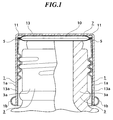
- Fig. 1 illustrates a container lid embodying the present invention.
- the container lid shown in Fig. 1 comprises a screw member 1, a hollow packing member 7 and an outer cap 13.
- Screw member 1 is detachably fitted around a threaded wall 3a of a container mouth 3.
- Outer cap 13 is fitted around screw member 1. More particularly, a lower portion 13a of outer cap 13 tightly overlaps a corresponding lower portion 1a of screw member 1. Further, the lower end of screw member 1 is rounded to the outside upwardly to form an annular groove, into which the lower end of outer cap 13 is inserted and fastened.
- packing member 7 is fitted below a closed top of outer cap 13 and above an open top 5 of screw member 1.
- packing member 7 of this embodiment comprises a pair of oppositely swelling or convexed skins 7a, 7b which are air-tightly connected with each other at rim portions thereof to provide an internal closed air chamber 10.
- a rim portion 11 of lower skin 7b is folded to clamp a flat rim portion of upper skin 7a.
- Packing member 7 is deformably press-fit positioned between the closed top of outer cap 13 and the open top of screw member 1 when the lid is fitted onto container mouth 3.
- packing member 7 is depressed and deformed between the closed top of outer cap 13 and the open top of screw member 1 when the container is lidded.
- the internal closed air chamber 10 of packing member 7 will act as an air spring and facilitate air-tight sealing of container mouth 3, which prevents deterioration and degeneration of contents such as cosmetic in the container for a longer period of time.
- a spring force stored in packing member 7 is readily released and, accordingly, packing member 7 is returned to its original shape.
- Screw member 1 and outer cap 13 are both made of aluminum.
- Packing member 7 is made of an alloyed aluminum, a typical example of which is referred to by "GM-145" manufactured by Sumitomo Aluminum Co., Ltd, having compositions and mechanical characteristics shown in the following Tables I and II.
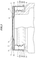
- Fig. 2 illustrate another embodiment of the present invention.
- a press member 15 is interposed between a closed top of outer cap 13 and a packing member 7.
- packing member 7 of this embodiment comprises a flat upper skin 7a and a swelling lower skin 7b to form therebetween an internal closed air chamber 10.
- a rim portion of upper skin 7a is folded to clamp a flat rim portion of lower skin 7b.
- Press member 15 includes a flat bottom 15a in contact with packing member 7 and an upstanding flange 15b fitted below the closed top and within the cylindrical wall of outer cap 13 so that there is another air chamber 16 between the closed top of outer cap 13 and flat bottom 15a of press member 15.
- Internal closed chamber 10 of packing member 7 cooperates with press member 15 to provide a sufficient air-tight sealing against the open top of mouth 3 when the container is capped.
- Press member 15 is also deformable and adjusts a degree of deformation of packing member 7.
- FIG. 3 illustrates still another embodiment of the present invention.
- a packing member 7 of this embodiment does not have a hollow structure, but has a substantially flat bottom 12 surrounding a convexed central area 7c, with an upstanding flange 7d, as shown in Figs. 6A to 6C, thereby providing a closed chamber 8 below a closed top of an outer cap 13.
- convexed central area 7c of packing member 7 is depressed and deformed within chamber 8.
- Such deformation of packing member 7 will act as a leaf spring and facilitate air-tight sealing of container mouth 3, thereby effectively preventing deterioration and degeneration of contents such as cosmetic in the container.
- Screw member 1 of this embodiment has somewhat different shape than in the preceding embodiments, which comprises an inner screw wall engageable with container mouth 3a, an outer wall 1a fitted within a wall of outer cap 13 and having an abutment 1b with the lower end of outer cap 13, and a horizontal top surface 5 connecting the upper ends of the inner screw wall and the outer wall. Horizontal top surface 5 will stably support thereon a bottom 12 of packing member 7 when the container is capped. This is merely a variation regarding a shape of screw member 1.
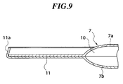
- FIGs. 7 to 10 show various modifications of hollow packing members 7.
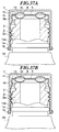
- a packing member 7 shown in Figs. 7A to 7C provides an internal closed air chamber 10 between a flat upper skin 7a and a swelling or convexed lower skin 7b.
- a rim portion of lower skin 7b is folded to overlap a rim portion of upper skin 7a.
- a packing member shown in Figs. 8A to 8C has an upside-down structure of that of Figs. 5A to 5C, which comprises a swelling upper skin 7a and a flat lower skin 7b to form therebetween an internal closed air chamber 10.
- a rim portion of lower skin 7b is folded to clamp a flat rim portion of upper skin 7a.
- Figs. 9 and 10 show modification of packing member 7 of Figs. 4A to 4C.
- both of upper and lower skins 7a and 7b have center swellings which cooperate with each other to define therebetween an internal closed air chamber 10.
- lower packing element 7b has a flat peripheral area 11 with an inwardly upstanding flange 11a engaging a flat face of upper skin 7a.
- both of upper and lower skins 7a and 7b have overlying upstanding flanges 11a.
- packing member 7 may have a multi-layer construction.
- the uppermost layer 7e is made of an alloyed aluminum having compositions and mechanical properties shown in Tables I and II, which is back-coated with a couple of aluminum foils 7g, 7g via adhesive layers 7f, 7f, respectively.
- a single or any number of aluminum foils 7g may be adhered to the underside of uppermost layer 7e.
- the container lid of the present invention is particularly used in combination of a container for cosmetic, for example.
- Cosmetic contained in the container will contact with the underside of packing member 7 every time when the lidded container is tilted inverted and shook. Therefore, packing member 7 preferably has, at its bottom, a resin layer 9 which prevents deterioration and degeneration of cosmetic in the container.
- Resin layer 9 may preferably be made of PET (polyethylene terephthalate) or PP (polypropylene).
- resin layer 9 is different in material than other components, that is screw member 1, outer cap 13 and packing member 7 which are all made of metallic material, such resin material of bottom layer 9 is very thin and, therefore, combustible during metallic material processing (re-dissolution of aluminum, for example).
- the container lid of this invention is an integral, unseparatable assembly but can be disposed in whole.
- Metallic material of the container lid is easily processed after disposal and reusable. Its whole disposal will not at all cause an environmental problem.
- Bottom layer 9 may be made by coating, film lamination or any other suitable method.
- Figs. 12 to 27 show various embodiments of the present invention which include packing member 7 with a bottom resin layer 9.
- the container lid of Fig. 12A employs a dish-like packing member 7 having a substantially horizontal bottom 12 with an upstanding peripheral flange 11 fitted air-tightly below the closed top and within the cylindrical wall of an outer cap 13, so that there is provided an internal closed space 8 therebetween.
- packing member 7 is depressed and deformed within space 8 when the container is lidded due to engagement between screw member 1 and threaded wall 3a of container mouth 3, as shown in Fig. 12B.
- packing member 7 will act as a leaf spring and facilitate air-tight sealing of container mouth 3, which prevents deterioration and degeneration of cosmetic in the container for a longer period of time.
- a spring force stored in packing member 7 is readily released and, accordingly, packing member 7 is returned to its original shape.
- packing member 7 has a back resin coating 9.
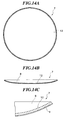
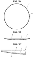
- Packing member 7 may have another dish-like shape, as shown in Fig. 14 and Fig. 15. In either embodiment, packing member 7 has no flange and simply comprises a round concaved bottom 12. The embodiment of Fig. 15 has more gently-sloping concaved bottom 12 than in the embodiment of Fig. 14.
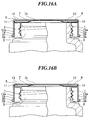
- FIGs. 16 and 17 illustrate a modified embodiment of the present invention.
- a hat-like packing member 7 used in this embodiment resembles one shown in Figs. 6A-6C but has a bottom resin layer 9.
- convexed central area 7c of packing member 7 is depressed and deformed within chamber 8, as shown in Fig. 16B.
- Such deformation of packing member 7 will act as a leaf spring and facilitate air-tight sealing of container mouth 3, thereby effectively preventing deterioration and degeneration of cosmetic in the container.
- packing member 7 is returned to its original shape.
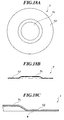
- Packing member 7 of Figs. 6A-6C may be modified as shown in Figs. 18A-18C which has no flange.
- FIGs. 19 and 20 illustrate still another embodiment of the present invention.
- a packing member 7 in this embodiment has a layered construction comprising upper and lower skins 7a and 7b.
- Upper skin 7a is similar to packing member 7 shown in Figs. 6A-6C, having a convexed central portion 7c surrounded by an unflanged flat peripheral face.
- Lower skin 7b has a flat bottom 12 with an upstanding flange 11 that engages a rim of the flat peripheral face of upper skin 7a, whereby upper skin 7a is fixedly supported and superposed on bottom 12 of lower skin 7b.
- an internal closed air chamber 10 is defined between convexed central portion 7c of upper skin 7a and flat bottom 12 of lower skin 7b.
- Upper skin 7a is made of aluminum.
- Lower skin 7b is also made of aluminum, but a resin layer 9 is formed onto its underside.
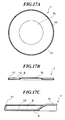
- Packing members 7 shown in Figs. 21, 22, 23A-23C, 24A-24C and 25A-25C are substantially the same as those shown in Figs. 9, 10, 4A-4C, 8A-8C and 7A-7C respectively, but have a bottom resin layer 9.
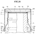
- FIG. 26 An embodiment shown in Fig. 26 has substantially the same construction as that of Fig. 2.
- This embodiment employs a packing member 7 shown in Fig. 27A-27C which resembles that of Figs. 5A-5C but a lower swelling skin 7b has a bottom resin layer 9.
- a press member 15 is interposed between a closed top of outer cap 13 and a packing member 7.
- this construction will provide double air-spring function and improve air-tight sealing capability of the container lid.
- Test samples No.1-1 to 1-4 are examples of the present invention. More specifically, Sample No. 1-1 was prepared as an example of the embodiment shown in Fig. 1 employing a hollow packing member 7 of Figs. 4A-4C. Sample No. 1-2 was prepared as an example of the embodiment shown in Figs. 12 and 13 in which a flanged packing member 7 has a bottom resin layer 9 by coating. Sample No. 1-3 was substantially identical to Sample No. 1-2 but the bottom resin layer was formed by film lamination. Sample No. 1-4 was substantially identical to Sample No. 1-1 but a packing member 7 was a multi-layered one as shown in Fig.
- Sample No. 2 uses a simple flat aluminum plate as a packing member
- Sample No. 3 uses a polypropylene sheet packing
- Sample No. 4 uses a cork packing.
- Weight of Vacant Container (g) Total Weight Weight of Contents (g) Reduction of Contents Before Test After Test Weight (g) Rate (%) 1-1 101.258 126.377 126.336 25.119 0.041 0.163 1-2 160.606 274.289 274.242 113.683 0.047 0.041 1-3 160.942 271.256 271.218 110.314 0.038 0.034 1-4 161.655 279.656 279.626 118.001 0.03 0.025 2 98.929 128.477 124.553 29.548 3.924 13.280 3 98.097 123.185 123.17 25.088 0.015 0.060 4 98.907 123.316 111.509 24.409 11.807 48.372
- a competent packing must have a sealing property that a reduction of contents is lower than 0.2%.
- the test results shown in Table III prove that the samples of the present invention (Sample Nos. 1-1 to 1-4) greatly exceed this requirement and may be used as excellent packing members.
- the sealing properties of these samples are equivalent to or still better than that of Sample No. 3 (polyethylene) which has been recognized as most preferable packing material.
- Sample No. 2 could not satisfy the above-described sealing requirement.
- Sample No. 4 showed an extraordinarily high reduction rate because a considerable amount of the contents leaked out through a porous cork packing.
- the container lid in the preceding embodiments may be used for a container of any material such as glass and plastic.
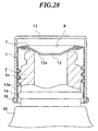
- Figs. 28 and 29 respectively show modifications of the embodiment shown in Fig. 3 which has an internal closed chamber 8 defined between a packing member 7 and an outer cap 13.
- packing member 7 in Figs. 28, 29 has a different shape rather than that of the embodiment of Fig. 3. More particularly, packing member 7 in Fig. 28 has a concaved bottom 12 with an inwardly downward slope surface 12a which provides a sealing contact with a container mouth 3 when the container is capped. In this embodiment, a slight contact between slope surface 12a and container mouth 3 will be enough to provide a sufficient degree of air-tightness of the container.
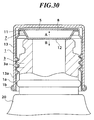
- a packing member 7 is fitted above an open top of a screw member 1 and below a closed top of an outer cap 13. However, as shown in Figs. 30-35, it can be fitted above a container mouth 3 and below a screw member 1.
- a dish-like packing member 7 has a horizontal flange 11 fitted beneath a horizontal top 5 of a screw member 1, and a horizontal bottom 12 fitted above a container mouth 3, thereby providing a hollow chamber 8 between top 5 of screw member 1 and packing member 7.
- packing member 7 is depressed and deformed in a direction A, and then tends to be returned to its original shape in the opposite direction B, which provides a sealing contact with container mouth 3.
- Figs. 31A and 31B show a modification of the embodiment of Fig. 30, in which a packing member 7 is fitted in a different way.
- the upper portion of the cylindrical wall of a screw member 1 has a plurality of spaced, inwardly projecting ridges 5a that engage with a plurality of recesses 11b formed at a horizontal flange portion 11 of packing member 7.
- a packing member 7 has an upstanding rim 11 that is press-fit within the upper cylindrical wall 5b of a screw member 1.
- a packing member 7 has a folded round rim 11 that is press-fit within the upper cylindrical wall 5b of the screw member 1.
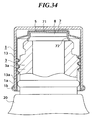
- a packing member 7 in Fig. 34 has a closed top 71 in abutment with the top 5 of a screw member 1 and an enlarged bottom opening. The lower end of an enlarged bottom 72 comes into contact with the top of a container mouth 3 when the container is capped.
- Fig. 32 may be modified as shown in Fig. 35 in which a spacer 18 is interposed between an outer cylindrical wall of a screw member 1 and an inner cylindrical wall of an outer cap 13.
- outer cap 13 may have an apparent diameter substantially identical to the container 20.
- the embodiments shown in Figs. 30-35 are particularly useful when the container is made of glass.
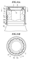
- a packing member 7 is also positioned between a screw member 1 and a container mouth 3, but is normally smaller than the outer cylindrical wall of screw member 1 to provide a gap G therebetween (see Fig. 36A).
- This embodiment is also particularly advantageous when used in combination with a glass container. When the container lid of this embodiment is too much tightly fastened onto container mouth 3, packing member 7 could be deformed outwardly within the gap G (see Fig. 36B) so that container mouth 3 would not be given an excessive force and thus prevented from damage.
- a packing member 7 is normally smaller than the outer cylindrical wall of screw member 1 and has an annular concaved portion for air-tight contact with a container mouth 3, as in the embodiment of Figs. 36A and 36B.
- a top 5 of screw member 1 has an annular convexed portion 5c positioned above the annular concaved portion of packing member 7 to define a hollow chamber 8 therebetween.
- Chamber 8 acts as an air cushion to prevent container mouth 3 from excessive depression.
- a packing member 7 normally smaller than the outer cylindrical wall of a screw member 1 has a central swell 7c that is engaged within a center hole 5d of a top 5 of screw member 1.
- there is another gap G between swell 7c and hole 5d which cooperates with gap G to allow a greater extent of deformation of packing member 7 and prevent more effectively damage of container mouth 3 when the container 20 is capped with an excessive force.
- Packing member 7 may have a flange 11 entirely or partly at a peripheral portion thereof. It may be upstanding (as in Figs. 36A and 36B) or horizontal (as in Figs. 37A and 37B).
- the packing member is preferably made of aluminum but may be of another metallic material.
- the packing member may have a flange of any desired shape, and may have no flange as shown in Figs. 7, 11, 14, 15, 18 and 25.
- An internal closed air chamber must be defined within or above the packing member but its shape is not limitative.
- the metallic packing member preferably have a resin layer that is formed by coating or film lamination on its underside, in order to prevent deterioration and degeneration of the contents, particularly cosmetic in the container.
- PET or PP is a favorable material to be used as such resin layer, but another suitable resin material may be used.
- an aluminum oxide coating may be formed on the underside of the metallic packing member by anodization.
Abstract
Description
- The present invention relates to a container lid, and more particularly to a lid for a cosmetic container.
- A cosmetic container should fulfill some requirements. It should look splendid to increase its commercial value. It is preferable to have a lighter weight and a lower manufacturing cost. A metallic container has a good appearance but is relatively heavy and costly. More importantly, when a metallic material is used as a packing of a container lid, it greatly degrades air-tightness of the container. Since most of recent cosmetic is volatile, the cosmetic container is required to have sufficient air-tightness. Accordingly, most of recent cosmetic container lid has its external parts made of metallic material and internal parts, especially a packing made of elastic material such as cork or resin material.
- The container lid is an integral assembly and, therefore, must be disposed in whole after use. When a container lid has two or more of different material parts, its whole disposal would cause an environmental problem.
- Accordingly, it is an object of the present invention to overcome the drawbacks and disadvantages of the prior art cosmetic container lids.
- Another object of the present invention is to provide a novel construction of a container lid which is made solely of metallic material but still capable of providing a sufficient degree of air-tightness when fitted onto a container body.
- According to an aspect of the present invention there is provided a container lid comprising a cylindrical metallic screw member detachably fittable onto a container mouth; a metallic outer cap fitted around the screw member; and a metallic packing member secured above an open top of the screw member and below a closed top of the outer cap, wherein the packing member is elastically deformable, when the lid is fitted onto the container mouth, to air-tightly seal the container mouth.
- In a preferred embodiment, the packing member has an internal closed air chamber which is deformable when the lid is fitted onto the container mouth. In a specific embodiment, the packing member has a substantially flat lower skin to be placed on the container mouth, a convexed upper skin and an internal closed air chamber formed between the flat lower skin and the convexed upper skin. In another embodiment, the packing member has a convexed lower skin to be placed on the container mouth, a substantially flat upper skin and an internal closed air chamber formed between the convexed lower skin and the flat upper skin. In still another embodiment, the packing member has convexed upper and lower skins and an internal closed air chamber formed between the convexed upper and lower skins. In each of these embodiments, the air chamber is deformable when the lid is fitted onto the container mouth.
- A press member may be positioned between the packing member and the closed top of the outer cap.
- The packing member may have a substantially flat plate with an upstanding rim flange fitted within and below the outer cap. A closed air chamber is formed between the packing member and the closed top of the outer cap.
- The packing member may comprise a hat-like member having a substantially flat peripheral area, with an upstanding rim flange fitted within and below the outer cap, and a convexed crown deformable when the lid is fitted onto the container mouth. In this embodiment, specifically, the upstanding rim flange is engaged within a cylindrical wall of the outer cap and the crown is in contact with the closed top of the outer cap.
- In another preferable embodiment, the underside of the packing member is covered with a resin layer. The resin layer may be formed by a resin coating, a laminated resin film, or a layer of an oxide of a base metal material of the packing member. The underside of the packing member is covered with an aluminum foil.
- Other objects and advantages of the present invention can be understood from the following description when read in conjunction with the accompanying drawings in which:
- Fig. 1 is a vertical cross-section of a container lid embodying the present invention, which is fitted onto a container mouth;
- Fig. 2 is a vertical cross-section of a container lid according to another embodiment of the present invention, which is fitted onto a container mouth;
- Fig. 3 is a vertical cross-section of a container lid according to still another embodiment of the present invention, which is fitted onto a container mouth;
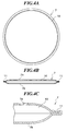
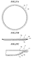
- Figs. 4A to 4C show an example of a packing member to be used in the container lid of the present invention, which is actually used in the embodiment of Fig. 1, in which Fig. 4A is a plan view, Fig. 4B is a vertical cross-section of the packing member and Fig. 4C is an enlarged vertical cross-section showing a part thereof;
- Figs. 5A to 5C show another example of the packing member, which is actually used in the embodiment of Fig. 2, in which Fig. 5A is a plan view, Fig. 5B is a vertical cross-section of the packing member and Fig. 5C is an enlarged vertical cross-section showing a part thereof;
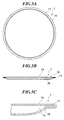
- Figs. 6A to 6C show still another example of the packing member, which is actually used in the embodiment of Fig. 3, in which Fig. 6A is a plan view, Fig. 6B is a vertical cross-section of the packing member and Fig. 6C is an enlarged vertical cross-section showing a part thereof;
- Figs. 7A to 7C show still another example of the packing member, in which Fig. 7A is a plan view, Fig. 7B is a vertical cross-section of the packing member and Fig. 7C is an enlarged vertical cross-section showing a part thereof;
- Figs. 8A to 8C show still another example of the packing member, in which Fig. 8A is a plan view, Fig. 8B is a vertical cross-section of the packing member and Fig. 8C is an enlarged vertical cross-section showing a part thereof;
- Fig. 9 is an enlarged vertical cross-section showing a part of a modified packing member;
- Fig. 10 is an enlarged vertical cross-section showing a part of a modified packing member;
- Figs. 11A to 11C show still another example of the packing member, in which Fig. 11A is a plan view, Fig. 11B is a vertical cross-section of the packing member and Fig. 11C is an enlarged vertical cross-section showing a part thereof;
- Figs. 12A and 12B are cross-sections showing a container lid according to still another embodiment of the present invention, which is fitted onto a container mouth;
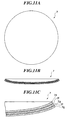
- Figs. 13A to 13C show a packing member used in the container lid of Figs. 12A and 12B, in which Fig. 13A is a plan view, Fig. 13B is a vertical cross-section of the packing member and Fig. 13C is an enlarged vertical cross-section showing a part thereof;
- Figs. 14A to 14C show another example of the packing member, in which Fig. 14A is a plan view, Fig. 14B is a vertical cross-section of the packing member and Fig. 14C is an enlarged vertical cross-section showing a part thereof.
- Figs. 15A to 15C show still another example of the packing member, in which Fig. 15A is a plan view, Fig. 15B is a vertical cross-section of the packing member and Fig. 15C is an enlarged vertical cross-section showing a part thereof;
- Figs. 16A and 16B are vertical cross-sections showing a container lid according to still another embodiment of the present invention, which is fitted onto a container mouth;
- Figs. 17A to 17C show a packing member used in the container lid of Figs. 16A and 16B, in which Fig. 17A is a plan view, Fig. 17B is a vertical cross-section of the packing member and Fig. 17C is an enlarged vertical cross-section showing a part thereof;
- Figs. 18A to 18C show a modified packing member, in which Fig. 18A is a plan view, Fig. 18B is a vertical cross-section of the packing member and Fig. 18C is an enlarged vertical cross-section showing a part thereof.
- Figs. 19A and 19B are vertical cross-section showing a container lid according to still another embodiment of the present invention, which is fitted onto a container mouth;
- Figs. 20A to 20C show a packing member used in the container lid of Figs. 19A and 19B, in which Fig. 20A is a plan view, Fig. 20B is a vertical cross-section of the packing member and Fig. 20C is an enlarged vertical cross-section showing a part thereof;
- Fig. 21 is an enlarged vertical cross-section showing a part of a modified packing member;
- Fig. 22 is an enlarged vertical cross-section showing a part of another modified packing member;
- Figs. 23A to 23C show still another modified packing member, in which Fig. 23A is a plan view, Fig. 23B is a vertical cross-section of the packing member and Fig. 23C is an enlarged vertical cross-section showing a part thereof;
- Figs. 24A to 24C show still another modified packing member, in which Fig. 24A is a plan view, Fig. 24B is a vertical cross-section of the packing member and Fig. 24C is an enlarged vertical cross-section showing a part thereof;
- Figs. 25A to 25C show still another modified packing member, in which Fig. 25A is a plan view, Fig. 25B is a vertical cross-section of the packing member and Fig. 25C is an enlarged vertical cross-section showing a part thereof;
- Fig. 26 is a vertical cross-section showing a container lid according to still another embodiment of the present invention, which is fitted onto a container mouth;
- Figs. 27A to 27C show a packing member used in the container lid of Fig. 26, in which Fig. 27A is a plan view, Fig. 27B is a vertical cross-section of the packing member and Fig. 27C is an enlarged vertical cross-section showing a part thereof;
- Fig. 28 is a vertical cross-section showing a container lid according to still another embodiment of the present invention fitted onto a container mouth;
- Fig. 29 is a vertical cross-section showing a container lid according to still another embodiment of the present invention fitted onto a container mouth;
- Fig. 30 is a vertical cross-section showing a container lid according to still another embodiment of the present invention fitted onto a container mouth;
- Figs. 31A and 31B show a container lid according to still another embodiment of the present invention fitted onto a container mouth, in which Fig. 31A is a vertical cross-section thereof and Fig. 31B is a horizontal cross-section taken along the line B-B in Fig. 31A;
- Fig. 32 is a vertical cross-section showing a container lid according to still another embodiment of the present invention fitted onto a container mouth;
- Fig. 33 is a vertical cross-section showing a container lid according to still another embodiment of the present invention fitted onto a container mouth;
- Fig. 34 is a vertical cross-section showing a container lid according to still another embodiment of the present invention fitted onto a container mouth;
- Fig. 35 is a vertical cross-section showing a container lid according to still another embodiment of the present invention fitted onto a container mouth;
- Fig. 36 is a vertical cross-section showing a container lid according to still another embodiment of the present invention fitted onto a container mouth;
- Fig. 37 is a vertical cross-section showing a container lid according to still another embodiment of the present invention fitted onto a container mouth; and
- Fig. 38 is a vertical cross-section showing a container lid according to still another embodiment of the present invention fitted onto a container mouth;
-
- Some preferred embodiments according to the present invention will be described hereinbelow in reference to the accompanying drawings. The same functional parts and elements are shown by the same reference numbers throughout the drawings.
- Fig. 1 illustrates a container lid embodying the present invention. The container lid shown in Fig. 1 comprises a
screw member 1, ahollow packing member 7 and anouter cap 13.Screw member 1 is detachably fitted around a threadedwall 3a of acontainer mouth 3.Outer cap 13 is fitted aroundscrew member 1. More particularly, alower portion 13a ofouter cap 13 tightly overlaps a correspondinglower portion 1a ofscrew member 1. Further, the lower end ofscrew member 1 is rounded to the outside upwardly to form an annular groove, into which the lower end ofouter cap 13 is inserted and fastened. - A
hollow packing member 7 is fitted below a closed top ofouter cap 13 and above anopen top 5 ofscrew member 1. As best seen in Figs. 4A to 4C, packingmember 7 of this embodiment comprises a pair of oppositely swelling orconvexed skins closed air chamber 10. Arim portion 11 oflower skin 7b is folded to clamp a flat rim portion ofupper skin 7a.Packing member 7 is deformably press-fit positioned between the closed top ofouter cap 13 and the open top ofscrew member 1 when the lid is fitted ontocontainer mouth 3. - In this embodiment, packing
member 7 is depressed and deformed between the closed top ofouter cap 13 and the open top ofscrew member 1 when the container is lidded. In this manner, the internalclosed air chamber 10 of packingmember 7 will act as an air spring and facilitate air-tight sealing ofcontainer mouth 3, which prevents deterioration and degeneration of contents such as cosmetic in the container for a longer period of time. When the container is uncapped, a spring force stored in packingmember 7 is readily released and, accordingly, packingmember 7 is returned to its original shape. -
Screw member 1 andouter cap 13 are both made of aluminum.Packing member 7 is made of an alloyed aluminum, a typical example of which is referred to by "GM-145" manufactured by Sumitomo Aluminum Co., Ltd, having compositions and mechanical characteristics shown in the following Tables I and II.Composition Si 0.20 wt% Mg 4.0-5.0 wt% Fe 0.35 wt% Cr 0.10 wt% Cu 0.15 wt% Zn 0.25 wt% Mn 0.20-0.50 wt% Ti 0.10 wt% Miscellaneous 0.15 wt% (in total) Al rest Mechanical Characteristic Gauge : 0.185 m Tensile Strength: 340-430 N/mZ Yield Strength: 280-340 N/mZ Elongation: minimum 3 % - Fig. 2 illustrate another embodiment of the present invention. In this embodiment, a
press member 15 is interposed between a closed top ofouter cap 13 and a packingmember 7. As best seen in Figs. 5A to 5C, packingmember 7 of this embodiment comprises a flatupper skin 7a and a swellinglower skin 7b to form therebetween an internalclosed air chamber 10. A rim portion ofupper skin 7a is folded to clamp a flat rim portion oflower skin 7b.Press member 15 includes aflat bottom 15a in contact with packingmember 7 and anupstanding flange 15b fitted below the closed top and within the cylindrical wall ofouter cap 13 so that there is anotherair chamber 16 between the closed top ofouter cap 13 andflat bottom 15a ofpress member 15. Internal closedchamber 10 of packingmember 7 cooperates withpress member 15 to provide a sufficient air-tight sealing against the open top ofmouth 3 when the container is capped.Press member 15 is also deformable and adjusts a degree of deformation of packingmember 7. - Fig. 3 illustrates still another embodiment of the present invention. A packing
member 7 of this embodiment does not have a hollow structure, but has a substantially flat bottom 12 surrounding a convexedcentral area 7c, with anupstanding flange 7d, as shown in Figs. 6A to 6C, thereby providing aclosed chamber 8 below a closed top of anouter cap 13. When the container is lidded, convexedcentral area 7c of packingmember 7 is depressed and deformed withinchamber 8. Such deformation of packingmember 7 will act as a leaf spring and facilitate air-tight sealing ofcontainer mouth 3, thereby effectively preventing deterioration and degeneration of contents such as cosmetic in the container. Once the container is uncapped to release a spring force stored in packingmember 7, packingmember 7 is returned to its original shape. -
Screw member 1 of this embodiment has somewhat different shape than in the preceding embodiments, which comprises an inner screw wall engageable withcontainer mouth 3a, anouter wall 1a fitted within a wall ofouter cap 13 and having anabutment 1b with the lower end ofouter cap 13, and a horizontaltop surface 5 connecting the upper ends of the inner screw wall and the outer wall. Horizontaltop surface 5 will stably support thereon a bottom 12 of packingmember 7 when the container is capped. This is merely a variation regarding a shape ofscrew member 1. - Figs. 7 to 10 show various modifications of
hollow packing members 7. A packingmember 7 shown in Figs. 7A to 7C provides an internalclosed air chamber 10 between a flatupper skin 7a and a swelling or convexedlower skin 7b. A rim portion oflower skin 7b is folded to overlap a rim portion ofupper skin 7a. A packing member shown in Figs. 8A to 8C has an upside-down structure of that of Figs. 5A to 5C, which comprises a swellingupper skin 7a and a flatlower skin 7b to form therebetween an internalclosed air chamber 10. A rim portion oflower skin 7b is folded to clamp a flat rim portion ofupper skin 7a. Figs. 9 and 10 show modification of packingmember 7 of Figs. 4A to 4C. More particularly, both of upper andlower skins closed air chamber 10. In Fig. 9,lower packing element 7b has a flatperipheral area 11 with an inwardlyupstanding flange 11a engaging a flat face ofupper skin 7a. In Fig. 10, both of upper andlower skins upstanding flanges 11a. - As shown in Fig. 11, packing
member 7 may have a multi-layer construction. In the illustrated embodiment, theuppermost layer 7e is made of an alloyed aluminum having compositions and mechanical properties shown in Tables I and II, which is back-coated with a couple ofaluminum foils adhesive layers aluminum foils 7g may be adhered to the underside ofuppermost layer 7e. - The container lid of the present invention is particularly used in combination of a container for cosmetic, for example. Cosmetic contained in the container will contact with the underside of packing
member 7 every time when the lidded container is tilted inverted and shook. Therefore, packingmember 7 preferably has, at its bottom, aresin layer 9 which prevents deterioration and degeneration of cosmetic in the container.Resin layer 9 may preferably be made of PET (polyethylene terephthalate) or PP (polypropylene). Althoughresin layer 9 is different in material than other components, that isscrew member 1,outer cap 13 and packingmember 7 which are all made of metallic material, such resin material ofbottom layer 9 is very thin and, therefore, combustible during metallic material processing (re-dissolution of aluminum, for example). This means that the container lid of this invention is an integral, unseparatable assembly but can be disposed in whole. Metallic material of the container lid is easily processed after disposal and reusable. Its whole disposal will not at all cause an environmental problem.Bottom layer 9 may be made by coating, film lamination or any other suitable method. - Figs. 12 to 27 show various embodiments of the present invention which include packing
member 7 with abottom resin layer 9. The container lid of Fig. 12A employs a dish-like packing member 7 having a substantially horizontal bottom 12 with an upstandingperipheral flange 11 fitted air-tightly below the closed top and within the cylindrical wall of anouter cap 13, so that there is provided an internalclosed space 8 therebetween. In this embodiment, packingmember 7 is depressed and deformed withinspace 8 when the container is lidded due to engagement betweenscrew member 1 and threadedwall 3a ofcontainer mouth 3, as shown in Fig. 12B. Such deformation of packingmember 7 will act as a leaf spring and facilitate air-tight sealing ofcontainer mouth 3, which prevents deterioration and degeneration of cosmetic in the container for a longer period of time. When the container is uncapped, a spring force stored in packingmember 7 is readily released and, accordingly, packingmember 7 is returned to its original shape. As best seen in Fig. 13C, packingmember 7 has aback resin coating 9. -
Packing member 7 may have another dish-like shape, as shown in Fig. 14 and Fig. 15. In either embodiment, packingmember 7 has no flange and simply comprises around concaved bottom 12. The embodiment of Fig. 15 has more gently-sloping concaved bottom 12 than in the embodiment of Fig. 14. - Figs. 16 and 17 illustrate a modified embodiment of the present invention. A hat-
like packing member 7 used in this embodiment resembles one shown in Figs. 6A-6C but has abottom resin layer 9. When the container is lidded, convexedcentral area 7c of packingmember 7 is depressed and deformed withinchamber 8, as shown in Fig. 16B. Such deformation of packingmember 7 will act as a leaf spring and facilitate air-tight sealing ofcontainer mouth 3, thereby effectively preventing deterioration and degeneration of cosmetic in the container. Once the container is uncapped to release a spring force stored in packingmember 7, packingmember 7 is returned to its original shape. -
Packing member 7 of Figs. 6A-6C may be modified as shown in Figs. 18A-18C which has no flange. - Figs. 19 and 20 illustrate still another embodiment of the present invention. A packing
member 7 in this embodiment has a layered construction comprising upper andlower skins Upper skin 7a is similar to packingmember 7 shown in Figs. 6A-6C, having a convexedcentral portion 7c surrounded by an unflanged flat peripheral face.Lower skin 7b has a flat bottom 12 with anupstanding flange 11 that engages a rim of the flat peripheral face ofupper skin 7a, wherebyupper skin 7a is fixedly supported and superposed onbottom 12 oflower skin 7b. Thus, an internalclosed air chamber 10 is defined between convexedcentral portion 7c ofupper skin 7a andflat bottom 12 oflower skin 7b.Upper skin 7a is made of aluminum.Lower skin 7b is also made of aluminum, but aresin layer 9 is formed onto its underside. - In this embodiment, when the container is capped, packing
member 7 is depressed and deformed between the closed top ofouter cap 13 and the open top ofscrew member 1. An air cushioning function ofchamber 10 permits deformation of packingmember 7 and facilitates air-tight sealing ofcontainer mouth 3, thus prevents deterioration and degeneration of cosmetic in the container. When the container is uncapped,chamber 10 is released from compression andcomposite packing member 7 is readily returned to its original shape. -
Packing members 7 shown in Figs. 21, 22, 23A-23C, 24A-24C and 25A-25C are substantially the same as those shown in Figs. 9, 10, 4A-4C, 8A-8C and 7A-7C respectively, but have abottom resin layer 9. - An embodiment shown in Fig. 26 has substantially the same construction as that of Fig. 2. This embodiment employs a packing
member 7 shown in Fig. 27A-27C which resembles that of Figs. 5A-5C but alower swelling skin 7b has abottom resin layer 9. In this embodiment, as in the embodiment of Fig. 2, apress member 15 is interposed between a closed top ofouter cap 13 and a packingmember 7. As having been described in connection with the embodiment of Fig. 2, this construction will provide double air-spring function and improve air-tight sealing capability of the container lid. - A test was conducted to show that the container lid according to the present invention has good sealing properties in comparison with the prior art one. Test samples No.1-1 to 1-4 are examples of the present invention. More specifically, Sample No. 1-1 was prepared as an example of the embodiment shown in Fig. 1 employing a
hollow packing member 7 of Figs. 4A-4C. Sample No. 1-2 was prepared as an example of the embodiment shown in Figs. 12 and 13 in which aflanged packing member 7 has abottom resin layer 9 by coating. Sample No. 1-3 was substantially identical to Sample No. 1-2 but the bottom resin layer was formed by film lamination. Sample No. 1-4 was substantially identical to Sample No. 1-1 but a packingmember 7 was a multi-layered one as shown in Fig. 11 having 3cm in thickness. As comparative test samples, Sample No. 2 uses a simple flat aluminum plate as a packing member, Sample No. 3 uses a polypropylene sheet packing and Sample No. 4 uses a cork packing. These test samples were subjected to an inverter test wherein they were fitted to the container at a fastening torque of 10kg and placed up-side-down in an atmosphere of 500mmHg for 30 minutes. The test results are shown in the following Table III.Sample No. Weight of Vacant Container (g) Total Weight Weight of Contents (g) Reduction of Contents Before Test After Test Weight (g) Rate (%) 1-1 101.258 126.377 126.336 25.119 0.041 0.163 1-2 160.606 274.289 274.242 113.683 0.047 0.041 1-3 160.942 271.256 271.218 110.314 0.038 0.034 1-4 161.655 279.656 279.626 118.001 0.03 0.025 2 98.929 128.477 124.553 29.548 3.924 13.280 3 98.097 123.185 123.17 25.088 0.015 0.060 4 98.907 123.316 111.509 24.409 11.807 48.372 - A competent packing must have a sealing property that a reduction of contents is lower than 0.2%. The test results shown in Table III prove that the samples of the present invention (Sample Nos. 1-1 to 1-4) greatly exceed this requirement and may be used as excellent packing members. The sealing properties of these samples are equivalent to or still better than that of Sample No. 3 (polyethylene) which has been recognized as most preferable packing material. On the other hand, Sample No. 2 could not satisfy the above-described sealing requirement. Sample No. 4 showed an extraordinarily high reduction rate because a considerable amount of the contents leaked out through a porous cork packing.
- The container lid in the preceding embodiments may be used for a container of any material such as glass and plastic.
- Figs. 28 and 29 respectively show modifications of the embodiment shown in Fig. 3 which has an internal
closed chamber 8 defined between a packingmember 7 and anouter cap 13. It can be noted that packingmember 7 in Figs. 28, 29 has a different shape rather than that of the embodiment of Fig. 3. More particularly, packingmember 7 in Fig. 28 has a concaved bottom 12 with an inwardlydownward slope surface 12a which provides a sealing contact with acontainer mouth 3 when the container is capped. In this embodiment, a slight contact betweenslope surface 12a andcontainer mouth 3 will be enough to provide a sufficient degree of air-tightness of the container. The bottom 12 of packingmember 7 in Fig. 29 has, in addition to the inwardlydownward slope surface 12a, an outwardlydownward slope surface 12b which provides supplemental or secondary sealing contact with the outer rim portion ofcontainer mouth 3. These embodiments are particularly advantageous when applied to acontainer 20 of fragile material such as glass. Any suitable means may be used to secure packingmember 7 to ascrew member 1. - In the preceding embodiments, a packing
member 7 is fitted above an open top of ascrew member 1 and below a closed top of anouter cap 13. However, as shown in Figs. 30-35, it can be fitted above acontainer mouth 3 and below ascrew member 1. - In Fig. 30, a dish-
like packing member 7 has ahorizontal flange 11 fitted beneath ahorizontal top 5 of ascrew member 1, and a horizontal bottom 12 fitted above acontainer mouth 3, thereby providing ahollow chamber 8 betweentop 5 ofscrew member 1 and packingmember 7. When the container is capped, packingmember 7 is depressed and deformed in a direction A, and then tends to be returned to its original shape in the opposite direction B, which provides a sealing contact withcontainer mouth 3. - Figs. 31A and 31B show a modification of the embodiment of Fig. 30, in which a packing
member 7 is fitted in a different way. The upper portion of the cylindrical wall of ascrew member 1 has a plurality of spaced, inwardly projectingridges 5a that engage with a plurality ofrecesses 11b formed at ahorizontal flange portion 11 of packingmember 7. In Fig. 32, a packingmember 7 has anupstanding rim 11 that is press-fit within the uppercylindrical wall 5b of ascrew member 1. In Fig. 33, a packingmember 7 has a folded round rim 11 that is press-fit within the uppercylindrical wall 5b of thescrew member 1. - A packing
member 7 in Fig. 34 has a closed top 71 in abutment with thetop 5 of ascrew member 1 and an enlarged bottom opening. The lower end of anenlarged bottom 72 comes into contact with the top of acontainer mouth 3 when the container is capped. - The embodiment of Fig. 32 may be modified as shown in Fig. 35 in which a
spacer 18 is interposed between an outer cylindrical wall of ascrew member 1 and an inner cylindrical wall of anouter cap 13. By this arrangement, even when there is a great difference between diameters of acontainer mouth 3 and a containermain body 20,outer cap 13 may have an apparent diameter substantially identical to thecontainer 20. The embodiments shown in Figs. 30-35 are particularly useful when the container is made of glass. - In Figs. 36A and 36B, a packing
member 7 is also positioned between ascrew member 1 and acontainer mouth 3, but is normally smaller than the outer cylindrical wall ofscrew member 1 to provide a gap G therebetween (see Fig. 36A). This embodiment is also particularly advantageous when used in combination with a glass container. When the container lid of this embodiment is too much tightly fastened ontocontainer mouth 3, packingmember 7 could be deformed outwardly within the gap G (see Fig. 36B) so thatcontainer mouth 3 would not be given an excessive force and thus prevented from damage. - In Figs. 37A and 37B, a packing
member 7 is normally smaller than the outer cylindrical wall ofscrew member 1 and has an annular concaved portion for air-tight contact with acontainer mouth 3, as in the embodiment of Figs. 36A and 36B. In this embodiment, a top 5 ofscrew member 1 has an annularconvexed portion 5c positioned above the annular concaved portion of packingmember 7 to define ahollow chamber 8 therebetween.Chamber 8 acts as an air cushion to preventcontainer mouth 3 from excessive depression. - In Figs. 38A and 38B, a packing
member 7 normally smaller than the outer cylindrical wall of ascrew member 1 has acentral swell 7c that is engaged within acenter hole 5d of a top 5 ofscrew member 1. In this case, there is another gap G betweenswell 7c andhole 5d, which cooperates with gap G to allow a greater extent of deformation of packingmember 7 and prevent more effectively damage ofcontainer mouth 3 when thecontainer 20 is capped with an excessive force. - The embodiments of Figs. 36-37 may have various modification.
Packing member 7 may have aflange 11 entirely or partly at a peripheral portion thereof. It may be upstanding (as in Figs. 36A and 36B) or horizontal (as in Figs. 37A and 37B). - Although preferred embodiments of the present invention has been described in detail in reference to the accompanying drawings, it is to be understood that many variations and modifications may be made without departing from spirits and scopes of the present invention as defined in the appended claims. The packing member is preferably made of aluminum but may be of another metallic material. The packing member may have a flange of any desired shape, and may have no flange as shown in Figs. 7, 11, 14, 15, 18 and 25. An internal closed air chamber must be defined within or above the packing member but its shape is not limitative.
- The metallic packing member preferably have a resin layer that is formed by coating or film lamination on its underside, in order to prevent deterioration and degeneration of the contents, particularly cosmetic in the container. PET or PP is a favorable material to be used as such resin layer, but another suitable resin material may be used. In place of the resin layer, an aluminum oxide coating may be formed on the underside of the metallic packing member by anodization.
Claims (24)
- A container lid comprising a metallic screw member detachably fittable onto a container mouth; a metallic outer cap fitted around said screw member; and a metallic packing member secured above an open top of said screw member and below a closed top of said outer cap, said packing member being elastically deformable, when the lid is fitted onto the container mouth, to air-tightly seals the container mouth.
- A container lid according to claim 1 wherein said packing member has an internal closed air chamber, said air chamber being deformable when the lid is fitted onto the container mouth.
- A container lid according to claim 1 wherein said packing member has a substantially flat lower skin to be placed on the container mouth, a convexed upper skin and an internal closed air chamber formed between said flat lower skin and said convexed upper skin, said air chamber being deformable when the lid is fitted onto the container mouth.
- A container lid according to claim 1 wherein said packing member has a convexed lower skin to be placed on the container mouth, a substantially flat upper skin and an internal closed air chamber formed between said convexed lower skin and said flat upper skin, said air chamber being deformable when the lid is fitted onto the container mouth.
- A container lid according to claim 1 wherein said packing member has convexed upper and lower skins and an internal closed air chamber formed between said convexed upper and lower skins, said air chamber being deformable when the lid is fitted onto the container mouth.
- A container lid according to claim 1 which further comprises a press member positioned between said packing member and the closed top of said outer cap.
- A container lid according to claim 1 wherein said packing member has a substantially flat plate with an upstanding rim flange fitted within and below said outer cap, a closed air chamber being formed between said packing member and the closed top of said outer cap.
- A container lid according to claim 1 wherein said packing member comprises a hat-like member having a substantially flat peripheral area, with an upstanding rim flange fitted within and below said outer cap, and a convexed crown deformable when the lid is fitted onto the container mouth.
- A container lid according to claim 8 wherein said upstanding rim flange is engaged within a cylindrical wall of said outer cap and said crown is in contact with the closed top of said outer cap.
- A container lid according to claim 1 wherein the underside of said packing member is covered with a resin layer.
- A container lid according to claim 1 wherein the underside of said packing member is covered with a resin coating.
- A container lid according to claim 1 wherein the underside of said packing member is covered with a laminated resin film.
- A container lid according to claim 1 wherein the underside of said packing member is coated with a layer of an oxide of a base metal material of said packing member.
- A container lid according to claim 1 wherein the underside of said packing member is covered with an aluminum foil.
- A container lid comprising a metallic screw member detachably fittable onto a container mouth; a metallic outer cap fitted around said screw member; and a metallic packing member secured to said screw member, said packing member being elastically deformable, when the lid is fitted onto the container mouth, to air-tightly seals the container mouth.
- A container lid according to claim 15 wherein said packing member has a rim flange fitted within said screw member to provide a hollow space below a closed top of said screw member.
- A container lid according to claim 16 wherein said rim flange extends horizontally.
- A container lid according to claim 16 wherein said rim flange is upstanding.
- A container lid according to claim 16 wherein said rim flange is an annular groove formed by folding inwardly a peripheral portion of said packing member.
- A container lid according to claim 15 wherein said packing member has a hat-like shape including an abutment with a top of said screw member and an enlarged lower portion for air-tight contact with the container mouth when the container lid is fitted onto the container.
- A container lid according to claim 1 or 15 wherein said packing member provides a circular contact line with the container mouth when the container lid is fitted onto the container.
- A container lid according to claim 1 or 15 which further comprises a spacer between said outer cap and said screw member so that said outer cap has a diameter equivalent to that of the container.
- A container lid according to claim 15 wherein there is a gap between a wall of said screw member and a periphery of said packing member.
- A container lid according to claim 23 wherein said packing member has a swell inserted into and engaged within a hole formed on a top of said screw member with an additional gap therebetween.
Applications Claiming Priority (9)
| Application Number | Priority Date | Filing Date | Title |
|---|---|---|---|
| JP23915897 | 1997-08-21 | ||
| JP23915897 | 1997-08-21 | ||
| JP239158/97 | 1997-08-21 | ||
| JP317790/97 | 1997-11-05 | ||
| JP31779097 | 1997-11-05 | ||
| JP31779097 | 1997-11-05 | ||
| JP16919398 | 1998-06-03 | ||
| JP169193/98 | 1998-06-03 | ||
| JP10169193A JPH11193041A (en) | 1997-08-21 | 1998-06-03 | Container cover |
Publications (2)
| Publication Number | Publication Date |
|---|---|
| EP0897876A2 true EP0897876A2 (en) | 1999-02-24 |
| EP0897876A3 EP0897876A3 (en) | 1999-11-24 |
Family
ID=27323136
Family Applications (1)
| Application Number | Title | Priority Date | Filing Date |
|---|---|---|---|
| EP98112896A Withdrawn EP0897876A3 (en) | 1997-08-21 | 1998-07-10 | Container lid |
Country Status (2)
| Country | Link |
|---|---|
| EP (1) | EP0897876A3 (en) |
| JP (1) | JPH11193041A (en) |
Cited By (2)
| Publication number | Priority date | Publication date | Assignee | Title |
|---|---|---|---|---|
| WO2014204068A1 (en) * | 2013-06-18 | 2014-12-24 | Ctk Co., Ltd | Cap for cosmetic case having active type sealing structure |
| WO2017083581A1 (en) | 2015-11-10 | 2017-05-18 | Tecnocap, Llc | Composite closure with support brace and method for making the same |
Families Citing this family (1)
| Publication number | Priority date | Publication date | Assignee | Title |
|---|---|---|---|---|
| KR20220032103A (en) * | 2019-09-25 | 2022-03-15 | 니혼 야마무라가라스 가부시키가이샤 | cap |
Citations (8)
| Publication number | Priority date | Publication date | Assignee | Title |
|---|---|---|---|---|
| US1346112A (en) * | 1918-03-04 | 1920-07-13 | Richard E Bruns | Sealing-cap |
| US1632086A (en) * | 1920-06-18 | 1927-06-14 | Lee Nixon | Closure |
| US2041403A (en) * | 1932-09-17 | 1936-05-19 | Alan R Fergusson | Closure cap for receptacles |
| US2058214A (en) * | 1933-07-03 | 1936-10-20 | Gutmann & Co Ferd | Container closure |
| GB652565A (en) * | 1948-10-08 | 1951-04-25 | Bertram Harley Penn | Improvements in orifice caps or stoppers |
| FR1061561A (en) * | 1952-08-21 | 1954-04-13 | Improvements to sealing washers for stopper caps and the like | |
| GB1495544A (en) * | 1973-11-06 | 1977-12-21 | United Glass Ltd | Sealing of containers |
| EP0411385A2 (en) * | 1989-08-03 | 1991-02-06 | Abbott Laboratories | Retortable composite closure for plastic containers |
Family Cites Families (1)
| Publication number | Priority date | Publication date | Assignee | Title |
|---|---|---|---|---|
| JPH04313438A (en) * | 1991-04-12 | 1992-11-05 | Toppan Printing Co Ltd | Metallic seaming cover |
-
1998
- 1998-06-03 JP JP10169193A patent/JPH11193041A/en active Pending
- 1998-07-10 EP EP98112896A patent/EP0897876A3/en not_active Withdrawn
Patent Citations (8)
| Publication number | Priority date | Publication date | Assignee | Title |
|---|---|---|---|---|
| US1346112A (en) * | 1918-03-04 | 1920-07-13 | Richard E Bruns | Sealing-cap |
| US1632086A (en) * | 1920-06-18 | 1927-06-14 | Lee Nixon | Closure |
| US2041403A (en) * | 1932-09-17 | 1936-05-19 | Alan R Fergusson | Closure cap for receptacles |
| US2058214A (en) * | 1933-07-03 | 1936-10-20 | Gutmann & Co Ferd | Container closure |
| GB652565A (en) * | 1948-10-08 | 1951-04-25 | Bertram Harley Penn | Improvements in orifice caps or stoppers |
| FR1061561A (en) * | 1952-08-21 | 1954-04-13 | Improvements to sealing washers for stopper caps and the like | |
| GB1495544A (en) * | 1973-11-06 | 1977-12-21 | United Glass Ltd | Sealing of containers |
| EP0411385A2 (en) * | 1989-08-03 | 1991-02-06 | Abbott Laboratories | Retortable composite closure for plastic containers |
Non-Patent Citations (1)
| Title |
|---|
| DATABASE WPI Section Ch, Week 9251 Derwent Publications Ltd., London, GB; Class A18, AN 92-419053 XP002085460 & JP 04 313438 A (TOPPAN PRINTING) , 5 November 1992 * |
Cited By (5)
| Publication number | Priority date | Publication date | Assignee | Title |
|---|---|---|---|---|
| WO2014204068A1 (en) * | 2013-06-18 | 2014-12-24 | Ctk Co., Ltd | Cap for cosmetic case having active type sealing structure |
| WO2017083581A1 (en) | 2015-11-10 | 2017-05-18 | Tecnocap, Llc | Composite closure with support brace and method for making the same |
| EP3374280A4 (en) * | 2015-11-10 | 2019-08-07 | Tecnocap, LLC | Composite closure with support brace and method for making the same |
| AU2016353152B2 (en) * | 2015-11-10 | 2022-05-19 | Tecnocap, Llc | Composite closure with support brace and method for making the same |
| US11453530B2 (en) | 2015-11-10 | 2022-09-27 | Tecnocap, Llc | Composite closure with support brace and method for making the same |
Also Published As
| Publication number | Publication date |
|---|---|
| JPH11193041A (en) | 1999-07-21 |
| EP0897876A3 (en) | 1999-11-24 |
Similar Documents
| Publication | Publication Date | Title |
|---|---|---|
| US3270904A (en) | Press-on turn-off cap | |
| US4466553A (en) | Composite container construction | |
| US9493288B2 (en) | Resealable moisture tight containers | |
| US20060261067A1 (en) | Molded plastic container combination including a snap-on snap ring | |
| US4154360A (en) | Overcap and container assembly | |
| US4166548A (en) | Containers and closures therefor | |
| US20060201944A1 (en) | Easily openable container lid with resealability and method of producing the same | |
| CA1249240A (en) | Vacuum indicating thermoplastic closure | |
| US11884449B2 (en) | Can lid, can and method for manufacturing a can lid | |
| KR20160045757A (en) | Easily openable container lid | |
| IE903841A1 (en) | "Plastics cap for blow-moulded plastics containers" | |
| US5242073A (en) | Resealable container closure | |
| HUT67404A (en) | Can with push-on cover | |
| EP0897876A2 (en) | Container lid | |
| US5803298A (en) | Container and container lid assembly with retaining ring | |
| US4757936A (en) | Sealed container and process of manufacture thereof | |
| US5685449A (en) | Lug lid for materials container with sacrificial depressions and annular expansion bead | |
| US4852793A (en) | Sealed container and process of manufacture thereof | |
| AU2004266755B2 (en) | Lever ring having a slanted flat strip | |
| EP0414249A2 (en) | Resealable container closure | |
| US20060081631A1 (en) | Polymeric coated storage container | |
| US2343716A (en) | Fiber container | |
| EP0546051B1 (en) | A closure device for a container | |
| GB2119343A (en) | Sheet-metal containers having press-in covers | |
| CN110267882A (en) | Closed cell |
Legal Events
| Date | Code | Title | Description |
|---|---|---|---|
| PUAI | Public reference made under article 153(3) epc to a published international application that has entered the european phase |
Free format text: ORIGINAL CODE: 0009012 |
|
| AK | Designated contracting states |
Kind code of ref document: A2 Designated state(s): AT BE CH CY LI |
|
| AX | Request for extension of the european patent |
Free format text: AL;LT;LV;MK;RO;SI |
|
| 17P | Request for examination filed |
Effective date: 19990702 |
|
| PUAL | Search report despatched |
Free format text: ORIGINAL CODE: 0009013 |
|
| AK | Designated contracting states |
Kind code of ref document: A3 Designated state(s): AT BE CH CY DE DK ES FI FR GB GR IE IT LI LU MC NL PT SE |
|
| AX | Request for extension of the european patent |
Free format text: AL;LT;LV;MK;RO;SI |
|
| AKX | Designation fees paid |
Free format text: AT BE CH CY LI |
|
| RBV | Designated contracting states (corrected) |
Designated state(s): DE FR GB IT |
|
| REG | Reference to a national code |
Ref country code: DE Ref legal event code: 8566 |
|
| 17Q | First examination report despatched |
Effective date: 20010402 |
|
| STAA | Information on the status of an ep patent application or granted ep patent |
Free format text: STATUS: THE APPLICATION IS DEEMED TO BE WITHDRAWN |
|
| 18D | Application deemed to be withdrawn |
Effective date: 20010814 |