EP0897216A2 - Piezoelectric resonator, its manufacturing method and its use as a sensor for measuring the concentration of a constituent in a fluid and/or defining the physical properties of the fluid - Google Patents
Piezoelectric resonator, its manufacturing method and its use as a sensor for measuring the concentration of a constituent in a fluid and/or defining the physical properties of the fluid Download PDFInfo
- Publication number
- EP0897216A2 EP0897216A2 EP98114232A EP98114232A EP0897216A2 EP 0897216 A2 EP0897216 A2 EP 0897216A2 EP 98114232 A EP98114232 A EP 98114232A EP 98114232 A EP98114232 A EP 98114232A EP 0897216 A2 EP0897216 A2 EP 0897216A2
- Authority
- EP
- European Patent Office
- Prior art keywords
- piezoelectric resonator
- fluid
- flow cell
- resonator
- sensor element
- Prior art date
- Legal status (The legal status is an assumption and is not a legal conclusion. Google has not performed a legal analysis and makes no representation as to the accuracy of the status listed.)
- Withdrawn
Links
- 239000012530 fluid Substances 0.000 title claims description 62
- 230000000704 physical effect Effects 0.000 title claims description 17
- 238000004519 manufacturing process Methods 0.000 title claims description 9
- 239000000470 constituent Substances 0.000 title 1
- 239000000758 substrate Substances 0.000 claims abstract description 26
- 238000000576 coating method Methods 0.000 claims abstract description 22
- 238000000034 method Methods 0.000 claims abstract description 17
- 239000011248 coating agent Substances 0.000 claims abstract description 11
- VYPSYNLAJGMNEJ-UHFFFAOYSA-N silicon dioxide Inorganic materials O=[Si]=O VYPSYNLAJGMNEJ-UHFFFAOYSA-N 0.000 claims description 43
- 239000010453 quartz Substances 0.000 claims description 41
- 239000010410 layer Substances 0.000 claims description 31
- 239000000126 substance Substances 0.000 claims description 31
- 239000013078 crystal Substances 0.000 claims description 26
- 239000012790 adhesive layer Substances 0.000 claims description 13
- 239000007788 liquid Substances 0.000 claims description 13
- 238000005259 measurement Methods 0.000 claims description 11
- PCHJSUWPFVWCPO-UHFFFAOYSA-N gold Chemical compound [Au] PCHJSUWPFVWCPO-UHFFFAOYSA-N 0.000 claims description 8
- 239000010931 gold Substances 0.000 claims description 8
- 229910052737 gold Inorganic materials 0.000 claims description 8
- 238000001816 cooling Methods 0.000 claims description 7
- 238000010438 heat treatment Methods 0.000 claims description 7
- 238000002347 injection Methods 0.000 claims description 7
- 239000007924 injection Substances 0.000 claims description 7
- 239000000853 adhesive Substances 0.000 claims description 6
- 230000001070 adhesive effect Effects 0.000 claims description 6
- VNNRSPGTAMTISX-UHFFFAOYSA-N chromium nickel Chemical compound [Cr].[Ni] VNNRSPGTAMTISX-UHFFFAOYSA-N 0.000 claims description 4
- 239000004020 conductor Substances 0.000 claims description 4
- 238000005530 etching Methods 0.000 claims description 4
- 229910052759 nickel Inorganic materials 0.000 claims description 4
- 229910052719 titanium Inorganic materials 0.000 claims description 4
- 229910004298 SiO 2 Inorganic materials 0.000 claims description 3
- 238000006243 chemical reaction Methods 0.000 claims description 3
- 229910052804 chromium Inorganic materials 0.000 claims description 3
- 238000004140 cleaning Methods 0.000 claims description 3
- 239000003599 detergent Substances 0.000 claims description 3
- 229910001120 nichrome Inorganic materials 0.000 claims description 3
- 238000002161 passivation Methods 0.000 claims description 3
- 230000002093 peripheral effect Effects 0.000 claims description 3
- 239000004033 plastic Substances 0.000 claims description 3
- XUIMIQQOPSSXEZ-UHFFFAOYSA-N Silicon Chemical compound [Si] XUIMIQQOPSSXEZ-UHFFFAOYSA-N 0.000 claims description 2
- 229910052710 silicon Inorganic materials 0.000 claims description 2
- 239000010703 silicon Substances 0.000 claims description 2
- 238000004544 sputter deposition Methods 0.000 claims description 2
- 229910052721 tungsten Inorganic materials 0.000 claims description 2
- 235000012431 wafers Nutrition 0.000 claims description 2
- 229910021489 α-quartz Inorganic materials 0.000 claims description 2
- 230000008878 coupling Effects 0.000 claims 1
- 238000010168 coupling process Methods 0.000 claims 1
- 238000005859 coupling reaction Methods 0.000 claims 1
- 230000000149 penetrating effect Effects 0.000 claims 1
- 229920001643 poly(ether ketone) Polymers 0.000 claims 1
- 238000003825 pressing Methods 0.000 claims 1
- 239000000463 material Substances 0.000 description 8
- 238000007789 sealing Methods 0.000 description 7
- 238000001514 detection method Methods 0.000 description 5
- 230000010354 integration Effects 0.000 description 4
- PXHVJJICTQNCMI-UHFFFAOYSA-N nickel Substances [Ni] PXHVJJICTQNCMI-UHFFFAOYSA-N 0.000 description 3
- 229910001080 W alloy Inorganic materials 0.000 description 2
- 238000009825 accumulation Methods 0.000 description 2
- 229910052782 aluminium Inorganic materials 0.000 description 2
- XAGFODPZIPBFFR-UHFFFAOYSA-N aluminium Chemical compound [Al] XAGFODPZIPBFFR-UHFFFAOYSA-N 0.000 description 2
- 238000013461 design Methods 0.000 description 2
- 239000012777 electrically insulating material Substances 0.000 description 2
- 238000003780 insertion Methods 0.000 description 2
- 230000037431 insertion Effects 0.000 description 2
- 238000009434 installation Methods 0.000 description 2
- 239000007791 liquid phase Substances 0.000 description 2
- 244000005700 microbiome Species 0.000 description 2
- 229920001296 polysiloxane Polymers 0.000 description 2
- 230000035882 stress Effects 0.000 description 2
- 239000010936 titanium Substances 0.000 description 2
- MAKDTFFYCIMFQP-UHFFFAOYSA-N titanium tungsten Chemical compound [Ti].[W] MAKDTFFYCIMFQP-UHFFFAOYSA-N 0.000 description 2
- 241000589248 Legionella Species 0.000 description 1
- 208000007764 Legionnaires' Disease Diseases 0.000 description 1
- 229910018487 Ni—Cr Inorganic materials 0.000 description 1
- 239000004696 Poly ether ether ketone Substances 0.000 description 1
- RTAQQCXQSZGOHL-UHFFFAOYSA-N Titanium Chemical compound [Ti] RTAQQCXQSZGOHL-UHFFFAOYSA-N 0.000 description 1
- 230000002411 adverse Effects 0.000 description 1
- 239000000427 antigen Substances 0.000 description 1
- 102000036639 antigens Human genes 0.000 description 1
- 108091007433 antigens Proteins 0.000 description 1
- JUPQTSLXMOCDHR-UHFFFAOYSA-N benzene-1,4-diol;bis(4-fluorophenyl)methanone Chemical compound OC1=CC=C(O)C=C1.C1=CC(F)=CC=C1C(=O)C1=CC=C(F)C=C1 JUPQTSLXMOCDHR-UHFFFAOYSA-N 0.000 description 1
- 238000005842 biochemical reaction Methods 0.000 description 1
- 239000011651 chromium Substances 0.000 description 1
- 239000002131 composite material Substances 0.000 description 1
- 150000001875 compounds Chemical class 0.000 description 1
- 238000000151 deposition Methods 0.000 description 1
- 230000000694 effects Effects 0.000 description 1
- 239000007772 electrode material Substances 0.000 description 1
- 238000005516 engineering process Methods 0.000 description 1
- 238000003018 immunoassay Methods 0.000 description 1
- 238000011065 in-situ storage Methods 0.000 description 1
- 238000011835 investigation Methods 0.000 description 1
- 230000002045 lasting effect Effects 0.000 description 1
- 229910052751 metal Inorganic materials 0.000 description 1
- 239000002184 metal Substances 0.000 description 1
- 238000001465 metallisation Methods 0.000 description 1
- 229920006260 polyaryletherketone Polymers 0.000 description 1
- 229920002530 polyetherether ketone Polymers 0.000 description 1
- 229920000642 polymer Polymers 0.000 description 1
- 238000002360 preparation method Methods 0.000 description 1
- 238000007639 printing Methods 0.000 description 1
- 230000000284 resting effect Effects 0.000 description 1
- 230000008646 thermal stress Effects 0.000 description 1
- WFKWXMTUELFFGS-UHFFFAOYSA-N tungsten Chemical compound [W] WFKWXMTUELFFGS-UHFFFAOYSA-N 0.000 description 1
- 239000010937 tungsten Substances 0.000 description 1
- XLYOFNOQVPJJNP-UHFFFAOYSA-N water Substances O XLYOFNOQVPJJNP-UHFFFAOYSA-N 0.000 description 1
Images

Classifications
-
- H—ELECTRICITY
- H03—ELECTRONIC CIRCUITRY
- H03H—IMPEDANCE NETWORKS, e.g. RESONANT CIRCUITS; RESONATORS
- H03H3/00—Apparatus or processes specially adapted for the manufacture of impedance networks, resonating circuits, resonators
- H03H3/007—Apparatus or processes specially adapted for the manufacture of impedance networks, resonating circuits, resonators for the manufacture of electromechanical resonators or networks
- H03H3/02—Apparatus or processes specially adapted for the manufacture of impedance networks, resonating circuits, resonators for the manufacture of electromechanical resonators or networks for the manufacture of piezoelectric or electrostrictive resonators or networks
-
- B—PERFORMING OPERATIONS; TRANSPORTING
- B01—PHYSICAL OR CHEMICAL PROCESSES OR APPARATUS IN GENERAL
- B01L—CHEMICAL OR PHYSICAL LABORATORY APPARATUS FOR GENERAL USE
- B01L3/00—Containers or dishes for laboratory use, e.g. laboratory glassware; Droppers
- B01L3/50—Containers for the purpose of retaining a material to be analysed, e.g. test tubes
- B01L3/502—Containers for the purpose of retaining a material to be analysed, e.g. test tubes with fluid transport, e.g. in multi-compartment structures
-
- G—PHYSICS
- G01—MEASURING; TESTING
- G01N—INVESTIGATING OR ANALYSING MATERIALS BY DETERMINING THEIR CHEMICAL OR PHYSICAL PROPERTIES
- G01N11/00—Investigating flow properties of materials, e.g. viscosity, plasticity; Analysing materials by determining flow properties
- G01N11/10—Investigating flow properties of materials, e.g. viscosity, plasticity; Analysing materials by determining flow properties by moving a body within the material
- G01N11/16—Investigating flow properties of materials, e.g. viscosity, plasticity; Analysing materials by determining flow properties by moving a body within the material by measuring damping effect upon oscillatory body
-
- G—PHYSICS
- G01—MEASURING; TESTING
- G01N—INVESTIGATING OR ANALYSING MATERIALS BY DETERMINING THEIR CHEMICAL OR PHYSICAL PROPERTIES
- G01N29/00—Investigating or analysing materials by the use of ultrasonic, sonic or infrasonic waves; Visualisation of the interior of objects by transmitting ultrasonic or sonic waves through the object
- G01N29/02—Analysing fluids
- G01N29/036—Analysing fluids by measuring frequency or resonance of acoustic waves
-
- H—ELECTRICITY
- H03—ELECTRONIC CIRCUITRY
- H03H—IMPEDANCE NETWORKS, e.g. RESONANT CIRCUITS; RESONATORS
- H03H9/00—Networks comprising electromechanical or electro-acoustic devices; Electromechanical resonators
- H03H9/15—Constructional features of resonators consisting of piezoelectric or electrostrictive material
- H03H9/17—Constructional features of resonators consisting of piezoelectric or electrostrictive material having a single resonator
- H03H9/19—Constructional features of resonators consisting of piezoelectric or electrostrictive material having a single resonator consisting of quartz
-
- B—PERFORMING OPERATIONS; TRANSPORTING
- B01—PHYSICAL OR CHEMICAL PROCESSES OR APPARATUS IN GENERAL
- B01L—CHEMICAL OR PHYSICAL LABORATORY APPARATUS FOR GENERAL USE
- B01L2200/00—Solutions for specific problems relating to chemical or physical laboratory apparatus
- B01L2200/02—Adapting objects or devices to another
- B01L2200/026—Fluid interfacing between devices or objects, e.g. connectors, inlet details
-
- B—PERFORMING OPERATIONS; TRANSPORTING
- B01—PHYSICAL OR CHEMICAL PROCESSES OR APPARATUS IN GENERAL
- B01L—CHEMICAL OR PHYSICAL LABORATORY APPARATUS FOR GENERAL USE
- B01L2300/00—Additional constructional details
- B01L2300/06—Auxiliary integrated devices, integrated components
- B01L2300/0627—Sensor or part of a sensor is integrated
- B01L2300/0663—Whole sensors
-
- B—PERFORMING OPERATIONS; TRANSPORTING
- B01—PHYSICAL OR CHEMICAL PROCESSES OR APPARATUS IN GENERAL
- B01L—CHEMICAL OR PHYSICAL LABORATORY APPARATUS FOR GENERAL USE
- B01L2300/00—Additional constructional details
- B01L2300/08—Geometry, shape and general structure
- B01L2300/0861—Configuration of multiple channels and/or chambers in a single devices
- B01L2300/0877—Flow chambers
-
- B—PERFORMING OPERATIONS; TRANSPORTING
- B01—PHYSICAL OR CHEMICAL PROCESSES OR APPARATUS IN GENERAL
- B01L—CHEMICAL OR PHYSICAL LABORATORY APPARATUS FOR GENERAL USE
- B01L2300/00—Additional constructional details
- B01L2300/18—Means for temperature control
-
- G—PHYSICS
- G01—MEASURING; TESTING
- G01N—INVESTIGATING OR ANALYSING MATERIALS BY DETERMINING THEIR CHEMICAL OR PHYSICAL PROPERTIES
- G01N2291/00—Indexing codes associated with group G01N29/00
- G01N2291/02—Indexing codes associated with the analysed material
- G01N2291/025—Change of phase or condition
- G01N2291/0256—Adsorption, desorption, surface mass change, e.g. on biosensors
Definitions
- the invention relates to a piezoelectric resonator, a method for Production of the resonator and its use as a sensor element, the implemented in a flow cell in a measuring system for detecting the Concentration of a substance contained in a fluid and / or the determination physical properties of the fluid can be integrated.
- the piezoelectric Resonator is flat and has electrical on its surface Contact areas for electrode and counter electrode on that with a signal source and a measuring device can be connected.
- the piezoelectric is used for the measurement Resonator brought into contact on one side with the fluid to be examined, the Resonator on a mass accumulation of the substance to be detected or on a Changing the physical properties of the fluid by changing its Resonance frequency and / or the vibration amplitude.
- Piezoelectric resonators usually have quartz crystal plates that for integration and electrical contact to an electrical resonant circuit Provide conductive contact areas over which the quartz crystal plate with a for the plate typical resonant AC voltage can be applied. Because of however, the platelet structure that can now be produced in a filigree manner can do that Resonance behavior of the resonator i.a. also by mechanical tensioning of the Platelets, caused by support beams or by contact with electrical Supply lines are adversely affected.
- Piezoelectric resonators serve among other things as active sensor elements for example Detection of a substance in a medium or to measure the concentration of the Substance in a liquid.
- Ensuring a tension-free mounting of a Quartz crystal plates must also have the Electrically contactable quartz crystal is liquid-tight compared to the investigating liquid to be isolated to cause electrical short circuits avoid.
- a sensor in this regard is described in DE 40 13 665.
- Known sensor provides a quartz crystal plate 4, which on both sides between two silicone seals clamped, and additionally with conductive adhesive bodies is contacted.
- the use of conductive adhesive has the consequence that the electrical contact cannot be released, which means, for example, that the Quartz crystal plates not possible or at least with a large manual Skill is connected.
- the quartz plates are glued or clamped in brackets, which makes Resonance behavior of the resonator itself due to mechanical tension can be affected.
- the piezoelectric resonator has both on its Contact areas on the front as well as on the back that lead to electrical Contacting an electrical resonant circuit or a measuring arrangement are to be connected.
- the integration of the piezoelectric resonator into one Housing with appropriate electrical contacting is time consuming and difficult. Consistent good quality of the electrical properties especially when using a piezoelectric resonator in a Bracket that allows the quartz crystal plate on one side with a It is not possible to bring the examining liquid into contact.
- Such brackets are also referred to as flow cells, which are a unit represent in which the quartz crystal plate is already electrically contacted with Connection electrodes is connected. There is also a defined inflow and outflow channel provided, via which the liquid to be examined is the piezoelectric Resonator can be added and removed in a targeted manner.
- a flow cell is possible for example from the above-mentioned article by M. Thomson in FIG. 4 forth.
- the invention is based on the object of a piezoelectric resonator develop the preamble of claim 1 such that it is reliable and without Risk of short circuits can be contacted electrically and integration in Carrier devices should be free of mechanical tension.
- the piezoelectric resonator in a sensor element according to the invention be integrable, that for detecting the concentration of a in a fluid contained substance or for determining physical properties of a fluid is designed and requires no complex sealing measures to a safe operation especially against electrical short circuit, too guarantee.
- the sensor element should be easy to manufacture and, in particular, should be such be designed so that cumbersome sealing measures are dispensed with can.
- the sensor element should in particular also be part of a flow cell be that allows easy replacement within a measuring arrangement. In particular, the flow cell is said to have no major structural and Handling technical effort electrically contactable and to any Liquid channel system can be connected in a fluid-tight manner.
- the invention is based on the idea of a piezoelectric resonator that is flat is formed with a on the surface of the piezoelectric resonator applied electrode and at least one counter electrode area in such a way design that a first side of the piezoelectric resonator only provides an electrode area that is electrically conductive with a Electrode area on the second side of the piezoelectric resonator is connected, on the electrically insulated from the electrode area Counter electrode area is provided.
- the piezoelectric resonator designed as a quartz crystal plate has one electrode or counter electrode arrangement according to the invention, which allows it to contact the piezoelectric resonator from only one side.
- the electrode area which is provided only on one side, over the edge of the quartz crystal plate to the opposite side out above, so that an electrical contact of the electrode area of the opposite side can be done.
- the opposite sees Side of the quartz crystal plate at least one contact area for the Counter electrode on, which is electrically isolated from the electrode area is arranged.
- Electrodes area on the opposite side of the quartz plate over the edge of the Platelets can also have electrical paths that run vertically through the platelet run, an electrical contact between the electrode areas on both Create surfaces of the plate.
- a central arrangement of a counter electrode area on the opposite side of the piezoelectric resonator because in this way a safe spatial spacing between that on the same side located electrode area to the counter electrode area can be realized.
- the spaces between the two are electrical conductive areas filled with electrically insulating material.
- electrically insulating material are also depending Requires two or more counter electrode areas on the resonator surface applicable.
- a shear oscillator is suitable as the material for the piezoelectric resonator ⁇ -quartz, which has been processed according to the AT cut.
- an additional adhesive layer directly on the surface of the Vibrating quartz flake applied preferably made of NiCr, Cr, Ni, Ti and / or W exists.
- a suitable material for the electrodes or counter-electrode areas preferably gold.
- Typical layer thicknesses for the adhesive layer move approximately between 10 and 50 nm, whereas the layer thickness from the electrically conductive material existing electrode or counter electrode layers be between 50 and 500 nm.
- Electrode and / or counter electrodes applied to the vibrating pad web-like heels, which are used to attach or Bond wires are provided.
- By providing concrete contact structures in the electrode and counter electrode areas can be component-specific Deviations that may affect any measurement results can be significantly restricted.
- the piezoelectric resonator according to the invention is as described above covered with an electrode area that extends from one side to the other Side either over the edge of the resonator or over electrical Connection channels extends to the other side of the resonator.
- an electrode area that extends from one side to the other Side either over the edge of the resonator or over electrical Connection channels extends to the other side of the resonator.
- Suitable selected substrate platelets which are available in any thickness and size to be acquired are placed on a carrier which holds each tile fixed at least one fixing point such that the plate for the Coating process is otherwise freely accessible.
- a shading mask is applied, wherein the shading mask is structured such that an area on the Platelet surface that should not be coated from a mask structure is covered.
- a fixing cover is placed on the Shading mask detachably applied, which is structured identically to the carrier.
- This arrangement which carries the substrate platelets to be coated, will appeal to you known coating process supplied in which without the process interrupt, both the top and the bottom of the substrate plates is coated.
- the support structure according to the invention provides a Coating of the plate from the side to the edge area Side, so that deposits surrounding the platelet, the platelet can be separated.
- the coating process is carried out in a conventional manner by means of CVD or sputtering processes.
- the substrate plates are first coated with an adhesive layer, which preferably consists of nickel chromium, nickel, titanium and / or tungsten.
- an electrically conductive layer is then deposited on the adhesive layer, which for many applications of the piezoelectric resonator consists of gold and has a layer thickness of approximately 50-500 nm.
- passivation layers are deposited on the substrate platelets, which consist of the following element compounds: SiC, Fi 3 N 4 , SiO 2 .
- a cleaning step in the support structure to provide introduced substrate plate which in the context of a known etching process can be performed.
- Materials of the carrier, the shading mask and the fixing cover choose that they are inert to the etching or Coating operations are.
- a suitable material for this is aluminum.
- the piezoelectric resonator according to the invention can basically be versatile Find use, such as in telecommunications equipment in which a very stable resonance frequency is needed, but the following are aimed Comments on the use of the piezoelectric resonator as a sensor element, with which the detection and detection of the concentration of dissolved in fluids Substances as well as for measuring physical properties of fluids is possible.
- the inventive electrode arrangement on the piezoelectric Resonator is a sensor element for detecting the concentration of one in one Fluid contained substance or for determining physical properties of a Fluids designed such that the sensor element of only one single side is electrically contactable and in this way with one for the Operation of the sensor element required signal source and a measuring arrangement is connectable.
- the sensor element allows it through Change in its resonance behavior when it comes into contact with the fluid under investigation regarding the physical properties of the fluid Detect viscosity, elasticity and density of the fluid. You bring up additionally a chemical or biochemical layer on the electrode area side, on which specifically accumulate or deposit substances that are contained in a fluid to be examined there is a mass accumulation on this side by the Resonance behavior of the piezoelectric resonator is also affected.
- the sensor element according to the invention in a trained according to the invention Flow cell integrated, preferably as a disc-like injection molded part is formed and according to the invention two electrical on its surface Has contact areas, which are connected to the Contact areas for the electrode and counter electrode of the sensor element are connectable.
- the sensor element closes exclusively with the Side having the electrode area and the injection molded part a cavity forming the flow cell volume with the cavity at least two Has passage channels through which the fluid to be examined can be supplied or discharged is.
- the particular advantage of the flow cell designed according to the invention is in that the flow cell as an easily replaceable module in one for the Measurement of the concentration of a substance in a liquid or the determination of the physical properties of a fluid designed measuring arrangement easily can be implemented and removed from it.
- the Flow cell through the mere contacting of the sensor element by means of Bond wires a tension-free fit that is not caused by tensile stress can act on the sensor element via connection wires, for example, is irritated.
- the actual electrical contacting of the flow cell takes place via Contact areas that are applied to the injection molded part and on which are suitable configured connection contacts can be placed.
- the flow cell according to the invention is suitable as a modular unit for one uncomplicated and quick use in a measuring arrangement, which is used to record the Concentration of a substance contained in a fluid and / or the determination physical properties of the fluid is designed. Because in all known Arrangements the insertion of the sensor element or that Flow cell including sensor element with great manual effort is connected, especially since fixed adhesive connections and cumbersome Sealing measures are used is a generic arrangement, such as it emerges, for example, from DE 40 13 665 C2, thereby according to the invention formed that a fluid channel system fluid-tight on one side of the Flow cell can be coupled and connection electrodes for a signal source and a measuring arrangement with the electrical contact areas on the opposite surface of the flow cell are connectable.
- the arrangement has a type of quick-change housing, which consists of two mutually definable housing parts is assembled, between which the flow cell only in a corresponding recess, which is on the outer contour the flow cell is adapted, can be inserted. More details on the Arrangement according to the invention are described in connection with the figures.
- Composite measuring arrangement is suitable for carrying out various types Measurements. So it is using suitable biochemical Reaction layers that can be applied on one side to the piezoelectric resonator are possible, the concentration of certain biochemical substances or To determine microorganisms.
- the arrangement can be used as an immunosensor be understood.
- the reaction kinetics can also be between at least two Substances are determined, with a substance on the resonator surface in immobilized form is deposited. Even without adding one biochemically active layer on the surface of the piezoelectric
- the arrangement according to the invention generally serves for resonators physical properties of fluids. In particular, the arrangement can also can be used as a detergent sensor or process rheometer.
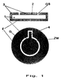
- Fig. 1 is a cross-sectional view through a coated in the upper part Piezoelectric resonator shown, the core of a quartz substrate 1st consists.
- the quartz substrate 1 designed as a quartz crystal plate is shown in FIG. 1 upper representation with an adhesive layer 2 largely completely with the exception of covered both open positions OS.
- the adhesive layer 2 consists of a Titanium-tungsten alloy and is also provided with an electrically conductive layer 3 plated, which is preferably made of gold.
- the electrode area E extends over the Edges of the piezoelectric resonator on top of the quartz substrate 1 on which a counter electrode area G is additionally deposited, opposite spatially spaced from the electrode area E and thus electrically insulated is arranged.
- An advantageous planar arrangement of electrode area E and Counter electrode area G is on the top of the piezoelectric resonator can be seen from the lower representation according to FIG. 1.
- the middle Counter electrode area G a web-like shoulder 4 through which an area for electrical contacting by means of bond wires is specified.
- the bare spatial spacing between electrode area E and Counter-electrode area G can be the space ZW with electrically insulating Material to be replenished to short-circuit effects caused, for example, by Exclude moisture completely.
- the manufacture of the piezoelectric resonator shown in Fig. 1 is below
- the support structures shown in FIG. 2 can be used. 1 a round quartz crystal plate is shown, but are also different Geometries, for example rectangular shapes, are conceivable.
- the untreated quartz plates the optionally subjected to an etching step for cleaning, on a support 5 applied, which is shown in the plan view on the left in Fig. 2.
- a support 5 which is shown in the plan view on the left in Fig. 2.
- Carrier 5 has a multiplicity of openings, each of which closes coating quartz plates are placed.
- the openings are like this shaped that the platelets with only with their peripheral edge area minimal support surface rest on the carrier 5. This ensures that Platelet is largely freely accessible for those in the coating process Platelet-depositing materials.
- a Shading mask 6 placed, the per to be coated quartz plates provides a ring region 7 which rests directly on the plate, so that this area is not coated during a coating process.
- a fixing cover 8 is used to fix the shading mask 6 how the carrier 5 is structured.
- the quartz substrates to be coated which are introduced between the support structure can be opened on both sides without opening the bracket Layer material can be coated without the coating process must be interrupted.
- Adhesive layer can be applied to the individual substrate surfaces typically a layer thickness of about 35 nm.
- suitable Materials are suitable for this purpose titanium-tungsten alloys.
- To separate the Electrically conductive material layers are basically suitable for any bondable Metallization layers, however, as mentioned above, in the most common cases use gold.
- Passivation layers such as SiC, Si 3 N 4 , SiO 2 or plasma polymer layers, can also be applied to the substrate surfaces in the same holder.
- the masks shown in FIG. 2 preferably consist of aluminum and typically have a mask diameter of 125 mm.
- a cross-sectional representation of a quartz crystal plate to be coated, that is introduced between the carrier 5 and the fixing cover 7 is shown in FIG. 3 shown.
- the quartz crystal plate 1 only protrudes at the stops Support in about 100 microns deep paragraphs A, which are incorporated into the carrier 5 are.
- the shading mask 6 is arranged, via which the fixing cover 7 is applied.
- the fixing cover 7 has connecting pins to the carrier 5, via which the Fixing cover can be fixed with the carrier 5.
- the fixing cover 8 can do this Coating material also get to the edges of the quartz plates, so that the electrode area makes electrical contact from one side to the other side can be.
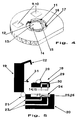
- Fig. 4 is an injection molded part designed according to the invention for realizing a Flow cell shown, both for manufacturing reasons and preferably made of plastic for reasons of chemical resistance Polyaryl ether ketone is made.
- the plastic offers PEEK on the one hand with thin layers acceptable heat transfers and on the other hand it is chemically resistant, heat-resistant up to 300 ° C and easy to machine.
- a recess 11 is worked into the center of the molded body, which is used for insertion of the sensor element described above is suitable.
- Flush on the support web 12 is a quartz crystal plate not shown in FIG. 4 placed on the side through three guide limits 16 in the center of the recess 11 is centered on the support web 12.
- the one resting on the support web 12 Sensor element is firmly fixed with a suitable adhesive, with excess Adhesive can flow into the peripheral groove 17 surrounding the support web 12.
- the sensor element closes between the underside of the quartz crystal plate and the inner surface 13 forming cavity, which forms the flow cell chamber.
- the electrodes and counter-electrode areas are made by means of the sensor element Bond wires connected to the electrical contact surfaces 9 and 10.
- the flow cell shown in Fig. 4 is a modular installation element consider and must be specially modified depending on the desired measuring tasks.
- the Flow cell allows quick installation and removal from a measuring arrangement, which is described below and can also be used as a consumable or to be understood as a disposable item.
- the arrangement consists of two Housing parts 19, 20 which can be pivoted relative to one another via a hinge joint 21 are connected.
- the upper housing part 19 also sees one Locking device in the form of a locking hook 22 through which the upper Housing part 19 with the lower housing part 20 are firmly supported against each other can.
- the lower housing part 20 is equipped with a fluid channel system 23, through its one channel, the fluid to be examined, the housing part 20 fed and discharged the fluid from the housing part via the other channel can be.
- the lower housing part provides a recess 24 which fits the outer contour of the one marked with the reference number 18 Flow cell is formed. Flush with those in the flow cell 18 incorporated through channels 14, 15 are the openings 25, 26 of the Fluid channel system 23 incorporated in the lower housing part 20.
- For fluid tight Connection between the lower housing part 20 and the flow cell 18 are each provided sealing rings 27.
- the flow cell 18 is as in the aforementioned case with reference to FIG 4 from an injection molded part into each of the two electrical contact areas 9, 10 are incorporated, which are connected via bonding wires 28 to the electrodes or Counter electrode areas on the sensor element 29 are electrically connected.
- the sensor element 29 closes a flow cell volume with the flow cell 30 a, in which the fluid to be examined with the underside of the sensor element 29 comes into contact, which affects the resonance behavior of the sensor element becomes.
- the flow cell 18 inserted into the recess 24 is by means of Spring contacts formed connecting electrodes 31 with the upper housing part 19 are connected, contacted.
- Spring contacts formed connecting electrodes 31 with the upper housing part 19 are connected, contacted.
- the measuring arrangement is particularly attractive because of simple pivoting and locking of both housing parts against each other Flow cell can be safely integrated into the arrangement. After The flow cell is completed by taking it out of the Measuring arrangement simple and inexpensive by implementing a new, to replace unused flow cell.
- the measuring arrangement is quasi as Quick-change measuring housing designed, which allows a variety differently prepared flow cells in immediate measurement sequence without great effort to exchange one another.
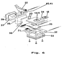
- the lower housing part 19 is made of a large number of individual components assembled: a support plate 32 to which the hinge joint 21 is articulated is used to hold a heat sink 33 and a base plate 34.
- the carrier plate has 32 cutouts for receiving a heating / cooling device 35, which is preferably designed as a Peltier element.
- a heating / cooling device 35 which is preferably designed as a Peltier element.
- the Base plate 34 has a recess on its top for receiving the Flow cell 18 and a recess to facilitate removal of the Flow cell 18 from the base plate 34.
- the supply and discharge lines of the Fluid channel systems 23 are mounted behind the base plate 34 and open into the Through channels 14 and 15, which are introduced symmetrically in the flow cell are.
- the upper housing part 19 consists of a pressure plate 36, an oscillator 37 also serves as a signal source for operating the piezoelectric resonator associated housing 38, a cover 39, the locking hook 22 and associated holding elements 40 and 41.
- the oscillator housing 38 also serves as a receptacle for the pressure plate 36 attached to the oscillator housing from below, as well as for attaching the Brackets 40 and 41.
- the measuring arrangement is placed over the locking hook 22 unlocked and the upper housing part 19 opened until it stops. Then the correspondingly prepared flow cell is preferably used Using tweezers, insert them into the recess in the base plate.
- the flow cell is connected to two spring contacts are carried out by the oscillator 37 through the housing 38 and the base plate 37, contacted.
- the fluidic sealing of the flow cell 18 against the base plate 35 takes place due to the resulting pressure on the sealing rings 27 (see FIG. 5 in the Base plate).
- the locking hook 22 is so far printed downwards until it engages in a corresponding grid.
- the advantage of this structure is that it can be exchanged quickly and easily Handling the flow cell.
- the inflow opening in the base plate is ready away from the actual measuring cell that drift in the oscillator frequency thermal stresses can be minimized. It is also through the design the measuring arrangement ensures that the fluid to be examined has a sufficiently long way through the tempered by the heating and cooling device Base plate goes through to provide a necessary temperature compensation for stable Experience measurements.
- the sensor element is on one side a biochemical, preferably coated with an antigen, so store selectively microorganisms or similar components from the sample to be examined Fluid on the sensor surface.
- the resulting mass change The resonator surface leads to a resonance change, which is reflected in the change affects the resonance frequency and / or vibration amplitude.
- the measuring arrangement is used for determination the physical properties of fluids, such as the detection of the Density, viscosity and / or elasticity of fluids. In this way, for example.
- Detergent sensors or process rheometers can be implemented.
Abstract
Description
Die Erfindung bezieht sich auf einen piezoelektrischen Resonator, ein Verfahren zur Herstellung des Resonators sowie dessen Einsatz als Sensorelement, das implementiert in einer Durchflußzelle in eine Meßanlage zum Erfassen der Konzentration eines in einem Fluid enthaltenen Stoffes und/oder der Bestimmung physikalischer Eigenschaften des Fluids integrierbar ist. Der piezoelektrische Resonator ist flächig ausgebildet und weist an seiner Oberfläche elektrische Kontaktbereiche für Elektrode- und Gegenelektrode auf, die mit einer Signalquelle sowie einer Meßeinrichtung verbindbar sind. Zur Messung wird der piezoelektrische Resonator einseitig mit dem zu untersuchenden Fluid in Kontakt gebracht, wobei der Resonator auf eine Massenanlagerung des zu erfassenden Stoffes oder auf eine Änderung der physikalischen Eigenschaften des Fluids durch Änderung seiner Resonanzfrequenz und/oder der Schwingungsamplitude anspricht.The invention relates to a piezoelectric resonator, a method for Production of the resonator and its use as a sensor element, the implemented in a flow cell in a measuring system for detecting the Concentration of a substance contained in a fluid and / or the determination physical properties of the fluid can be integrated. The piezoelectric Resonator is flat and has electrical on its surface Contact areas for electrode and counter electrode on that with a signal source and a measuring device can be connected. The piezoelectric is used for the measurement Resonator brought into contact on one side with the fluid to be examined, the Resonator on a mass accumulation of the substance to be detected or on a Changing the physical properties of the fluid by changing its Resonance frequency and / or the vibration amplitude.
Piezoelektrische Resonatoren weisen in aller Regel Schwingquarzplättchen auf, die zur Integration und elektrischen Kontaktierung an einen elektrischen Schwingkreis leitende Kontaktbereiche vorsehen, über die das Schwingquarzplättchen mit einer für das Plättchen typischen resonanten Wechselspannung beaufschlagbar ist. Aufgrund der mittlerweile in filigraner Weise herstellbaren Plättchenstruktur kann jedoch das Resonanzverhalten des Resonators u.a. auch durch mechanisches Verspannen des Plättchens, verursacht durch Halteträger oder durch Kontaktieren mit elektrischen Zuleitungen, nachteilhaft beeinträchtigt werden.Piezoelectric resonators usually have quartz crystal plates that for integration and electrical contact to an electrical resonant circuit Provide conductive contact areas over which the quartz crystal plate with a for the plate typical resonant AC voltage can be applied. Because of however, the platelet structure that can now be produced in a filigree manner can do that Resonance behavior of the resonator i.a. also by mechanical tensioning of the Platelets, caused by support beams or by contact with electrical Supply lines are adversely affected.
Ein Beispiel zum elektrischen Kontaktieren eines Schwingquarzplättchens, das in
einem Halteträger fixiert ist, ist in der DE 34 46 612 A1 beschrieben. Das
Schwingquarzplättchen 8 weist flächig auf seiner Oberfläche abgeschiedene
Elektroden 301 auf und ist zwischen zwei Haltebügeln 201 sowohl räumlich fixiert als
auch elektrisch kontaktiert. Nachteilhaft bei dieser bekannten Anordnung ist jedoch,
daß das zwischen den Teilen 7 eingeklebte Plättchen 8 bereits durch geringste
Kraftmomente, die auf beiden getrennt voneinander angeordneten Teilen 7 einwirken
können, mechanisch verspannt werden kann, wodurch das Resonanzverhalten des
Plättchens 8 beeinflußt wird.An example for the electrical contacting of a quartz crystal plate, which in
a support bracket is fixed is described in
Piezoelektrische Resonatoren dienen u.a. als aktive Sensorelemente bspw. zum Nachweis eines Stoffes in einem Medium bzw. zum Messen der Konzentration des Stoffes in einer Flüssigkeit. Neben dem vorstehend genannten Problem zur Gewährleistung einer möglichst spannungsfreien Halterung eines Schwingquarzplättchens muß beim Umgang mit Flüssigkeiten zusätzlich der elektrisch zu kontaktierende Schwingquarz flüssigkeitsdicht gegenüber der zu untersuchenden Flüssigkeit isoliert werden, um elektrische Kurzschlüsse zu vermeiden. In der DE 40 13 665 ist ein diesbezüglicher Sensor beschrieben. Der bekannte Sensor sieht ein Schwingquarzplättchen 4 vor, das beidseitig zwischen zwei Silikondichtungen eingeklemmt, und zusätzlich mit leitfähigen Klebstoffkörpern kontaktiert ist. Die Verwendung von leitfähigem Klebstoff hat jedoch zur Folge, daß die elektrische Kontaktierung nicht lösbar ist, wodurch bspw. ein Wechsel des Schwingquarzplättchens nicht möglich oder zumindest mit großem handwerklichen Geschick verbunden ist. Ebenso müssen die Silikondichtungen, die das Schwingquarzplättchen allseitig umfassen hochgenau gearbeitet sein, um mögliche Verformungen im Plättchen zu vermeiden.Piezoelectric resonators serve among other things as active sensor elements for example Detection of a substance in a medium or to measure the concentration of the Substance in a liquid. In addition to the problem mentioned above Ensuring a tension-free mounting of a Quartz crystal plates must also have the Electrically contactable quartz crystal is liquid-tight compared to the investigating liquid to be isolated to cause electrical short circuits avoid. A sensor in this regard is described in DE 40 13 665. Of the Known sensor provides a quartz crystal plate 4, which on both sides between two silicone seals clamped, and additionally with conductive adhesive bodies is contacted. However, the use of conductive adhesive has the consequence that the electrical contact cannot be released, which means, for example, that the Quartz crystal plates not possible or at least with a large manual Skill is connected. Likewise, the silicone seals that the Vibrating quartz plates encompass all sides to be worked to the highest possible Avoid deformation in the plate.
Ein ähnlicher Aufbau zum Erfassen bzw. Messen der Konzentration bestimmter
Stoffe, die in einer Flüssigkeit gelöst sind unter Verwendung eines
Schwingquarzplättchens ist in dem Artikel von W. Stöckl und R. Schumacher, ![]()
![]()
Allen bekannten, auf der Basis piezoelektrischer Resonatoren arbeitenden Sensoren zur Messung von Stoffkonzentrationen in Flüssigkeiten sowie auch zur Erfassung von physikalischen Eigenschaften von Flüssigkeiten haften zusammenfassend folgende Nachteile an: All known sensors based on piezoelectric resonators for measuring substance concentrations in liquids as well as for recording summarize physical properties of liquids the following disadvantages:
Die Schwingquarzplättchen sind in Halterungen geklebt oder geklemmt, wodurch das Resonanzverhalten des Resonators selbst durch mechanische Verspannungen beeinträchtigt werden kann. Auch sind geklebte und geklemmte elektrische Kontakte auf der Oberfläche des Schwingquarzplättchens insbesondere für den Einsatz zum Messen von Stoffkonzentrationen in Flüssigkeiten nicht uneingeschränkt betriebssicher. Vorkehrungen müssen getroffen werden, um elektrische Kurzschlüsse zu vermeiden. Eine dauerhafte und gleichbleibende Qualität der Kontaktierung läßt sich auf diese Weise nicht erreichen.The quartz plates are glued or clamped in brackets, which makes Resonance behavior of the resonator itself due to mechanical tension can be affected. There are also glued and clamped electrical contacts on the surface of the quartz crystal plate, especially for use in Measurement of substance concentrations in liquids is not unlimited reliable. Precautions must be taken to ensure electrical Avoid short circuits. A lasting and constant quality of Contacting cannot be achieved in this way.
In allen bekannten Fällen weist der piezoelektrische Resonator sowohl auf seiner Vorder- als auch auf seiner Rückseite Kontakbereiche auf, die zur elektrischen Kontaktierung an einen elektrischen Schwingkreis bzw. an eine Meßanordnung anzuschließen sind. Die Integration des piezoelektrischen Resonators in eine Gehäusung mit entsprechender elektrischer Kontaktierung ist zeitaufwendig und schwierig. Eine gleichbleibende gute Qualität der elektrischen Eigenschaften insbesondere bei Verwendung eines piezoelektrischen Resonators in einer Halterung, die es gestattet das Schwingquarzplättchen einseitig mit einer zu untersuchenden Flüssigkeit in Kontakt zu bringen, ist nicht möglich.In all known cases, the piezoelectric resonator has both on its Contact areas on the front as well as on the back that lead to electrical Contacting an electrical resonant circuit or a measuring arrangement are to be connected. The integration of the piezoelectric resonator into one Housing with appropriate electrical contacting is time consuming and difficult. Consistent good quality of the electrical properties especially when using a piezoelectric resonator in a Bracket that allows the quartz crystal plate on one side with a It is not possible to bring the examining liquid into contact.
Derartige Halterungen werden auch als Durchflußzellen bezeichnet, die eine Einheit darstellen, in der das Schwingquarzplättchen bereits elektrisch kontaktiert mit Anschlußelektroden verbunden ist. Ferner ist ein definierter Zu- und Abflußkanal vorgesehen, über die die zu untersuchende Flüssigkeit dem piezoelektrischen Resonator gezielt zu- und wieder abführbar ist. Eine derartige Durchflußzelle geht beispielsweise aus dem obenstehend genannten Artikel von M. Thomson in Fig. 4 hervor.Such brackets are also referred to as flow cells, which are a unit represent in which the quartz crystal plate is already electrically contacted with Connection electrodes is connected. There is also a defined inflow and outflow channel provided, via which the liquid to be examined is the piezoelectric Resonator can be added and removed in a targeted manner. Such a flow cell is possible for example from the above-mentioned article by M. Thomson in FIG. 4 forth.
Für Anwender derartiger Durchflußzellen sind ein hoher Zeitaufwand und handwerkliches Geschick beim Wechseln der Zelle notwendig. Insbesondere im Bereich der Biosensorik sind häufige Wechselmaßnahmen notwendig, zumal für jeden unterschiedlich zu erfassenden Stoff eine eigens präparierte Durchflußzelle notwendig ist. Die mit dem Wechsel verbundenen Arbeiten stehen einer kommerziellen Verbreitung von piezoelektrischen Resonatoren entgegen.For users of such flow cells are a lot of time and manual skill necessary when changing the cell. Especially in In the area of biosensor technology, frequent change measures are necessary, especially for each substance to be detected differently has a specially prepared flow cell necessary is. The work associated with the change is one against the commercial spread of piezoelectric resonators.
Der Erfindung liegt die Aufgabe zugrunde, einen piezoelektrischen Resonator gemäß
dem Oberbegriff des Anspruchs 1 derart weiterzubilden, daß er zuverlässig und ohne
Gefahr von Kurzschlüssen elektrisch kontaktiert werden kann und eine Integration in
Trägervorrichtungen frei von mechanischen Verspannungen erfolgen soll. Überdies
soll der piezoelektrische Resonator in ein erfindungsgemäßes Sensorelement
integrierbar sein, das zum Erfassen der Konzentration eines in einem Fluid
enthaltenen Stoffes oder zur Bestimmung physikalischer Eigenschaften eines Fluids
ausgelegt ist und keine aufwendigen Dichtungsmaßnahmen erfordert, um einen
sicheren Betrieb insbesondere gegenüber elektrischem Kurzschluß, zu
gewährleisten. Das Sensorelement soll leicht herstellbar und insbesondere derart
konzipiert sein, so daß auf umständliche Dichtungsmaßnahmen verzichtet werden
kann. Das Sensorelement soll insbesondere auch Bestandteil einer Durchflußzelle
sein, die ein leichtes Auswechseln innerhalb einer Meßanordnung gestattet.
Insbesondere soll die Durchflußzelle ohne großen konstruktiven und
handhabungstechnischen Aufwand elektrisch kontaktierbar und an ein etwaiges
Flüssigkeitskanalsystem fluiddicht anschließbar sein.The invention is based on the object of a piezoelectric resonator
develop the preamble of
Der Erfindung liegt die Idee zugrunde, einen piezoelektrischen Resonator, der flächig ausgebildet ist, mit einem auf der Oberfläche des piezoelektrischen Resonators aufgebrachten Elektroden- und mindestens einem Gegenelektrodenbereich derart auszugestalten, daß eine erste Seite des piezoelektrischen Resonators ausschließlich einen Elektrodenbereich vorsieht, der elektrisch leitend mit einem Elektrodenbereich auf der zweiten Seite des piezoelektrischen Resonators verbunden ist, auf der gegenüber dem Elektrodenbereich elektrisch isoliert der Gegenelektrodenbereich vorgesehen ist.The invention is based on the idea of a piezoelectric resonator that is flat is formed with a on the surface of the piezoelectric resonator applied electrode and at least one counter electrode area in such a way design that a first side of the piezoelectric resonator only provides an electrode area that is electrically conductive with a Electrode area on the second side of the piezoelectric resonator is connected, on the electrically insulated from the electrode area Counter electrode area is provided.
Der als Schwingquarzplättchen ausgebildete piezoelektrische Resonator weist eine erfindungsgemäße Elektroden- bzw. Gegenelektrodenanordnung auf, die es erlaubt den piezoelektrischen Resonator von nur einer einzigen Seite aus zu kontaktieren. Hierbei ist der Elektrodenbereich, der ausschließlich auf einer Seite vorgesehen ist, über den Rand des Schwingquarzplättchen auf die gegenüberliegende Seite nach oben geführt, so daß eine elektrische Kontaktierung des Elektrodenbereiches von der gegenüberliegenden Seite erfolgen kann. Zudem sieht die gegenüberliegende Seite des Schwingquarzplättchens wenigstens einen Kontaktbereich für die Gegenelektrode auf, der elektrisch isoliert gegenüber dem Elektrodenbereich angeordnet ist.The piezoelectric resonator designed as a quartz crystal plate has one electrode or counter electrode arrangement according to the invention, which allows it to contact the piezoelectric resonator from only one side. Here, the electrode area, which is provided only on one side, over the edge of the quartz crystal plate to the opposite side out above, so that an electrical contact of the electrode area of the opposite side can be done. In addition, the opposite sees Side of the quartz crystal plate at least one contact area for the Counter electrode on, which is electrically isolated from the electrode area is arranged.
Alternativ oder zusätzlich zu der elektrischen Kontaktierung des Elektrodenbereiches auf die gegenüberliegende Schwingquarzplättchenseite über den Rand des Plättchens, können auch elektrische Leitpfade die senkrecht durch das Plättchen verlaufen, einen elektrischen Kontakt zwischen den Elektrodenbereichen auf beiden Oberflächen des Plättchens herstellen.Alternatively or in addition to the electrical contacting of the electrode area on the opposite side of the quartz plate over the edge of the Platelets can also have electrical paths that run vertically through the platelet run, an electrical contact between the electrode areas on both Create surfaces of the plate.
Vorteilhaft ist eine mittige Anordnung eines Gegenelektrodenbereiches auf der gegenüberliegenden Seite des piezoelektrischen Resonators, da auf diese Weise eine sichere räumliche Beabstandung zwischen dem auf der gleichen Seite befindlichen Elektrodenbereich zum Gegenelektrodenbereich realisierbar ist.A central arrangement of a counter electrode area on the opposite side of the piezoelectric resonator because in this way a safe spatial spacing between that on the same side located electrode area to the counter electrode area can be realized.
Alternativ oder zusätzlich sind die Zwischenräume zwischen beiden elektrisch leitenden Bereichen mit elektrisch isolierendem Material aufgefüllt. Auch sind je nach Bedarf zwei oder mehr Gegenelektrodenbereiche auf der Resonatoroberfläche aufbringbar.Alternatively or additionally, the spaces between the two are electrical conductive areas filled with electrically insulating material. Are also depending Requires two or more counter electrode areas on the resonator surface applicable.
Als Material für den piezoelektrischen Resonator eignet sich ein Scherschwinger aus α-Quarz, der gemäß dem AT-Schnitt bearbeitet worden ist.A shear oscillator is suitable as the material for the piezoelectric resonator α-quartz, which has been processed according to the AT cut.
Um eine ausreichende Haftfähigkeit zwischen dem Schwingquarzplättchen und den auf diesem aufzubringenden Elektroden- bzw. Gegenelektrodenschichten zu erreichen, ist zusätzliche eine Haftschicht direkt auf der Oberfläche des Schwingquarzplättchens aufgebracht, die vorzugsweise aus NiCr, Cr, Ni, Ti und/oder W besteht. Als Material für die Elektroden bzw. Gegenelektrodenbereiche eignet sich vorzugsweise Gold. Typische Schichtdicken für die Haftschicht bewegen sich etwa zwischen 10 und 50 nm, wohingegen die Schichtdicke der aus dem elektrisch leitenden Material bestehenden Elekroden- bzw. Gegenelektrodenschichten etwa zwischen 50 bis 500 nm betragen.To ensure sufficient adhesion between the quartz crystal plate and the on this to be applied electrode or counter electrode layers achieve is an additional adhesive layer directly on the surface of the Vibrating quartz flake applied, preferably made of NiCr, Cr, Ni, Ti and / or W exists. A suitable material for the electrodes or counter-electrode areas preferably gold. Typical layer thicknesses for the adhesive layer move approximately between 10 and 50 nm, whereas the layer thickness from the electrically conductive material existing electrode or counter electrode layers be between 50 and 500 nm.
Zur elektrischen Kontaktierung des piezoelektrischen Resonators weisen die auf dem Schwingquatzplättchen aufgebrachten Elektroden- und/oder Gegenelektroden stegartig ausgebildete Absätze auf, die zum Anbringen von Anschluß bzw. Bonddrähten vorgesehen sind. Durch das Vorsehen konkreter Kontaktstrukturen in den Elektroden- und Gegenelektrodenbereichen können bauelementspezifische Abweichungen, die sich möglicherweise auf etwaige Meßergebnisse auswirken können, erheblich eingeschränkt werden.For electrical contacting of the piezoelectric resonator, the have on the Electrode and / or counter electrodes applied to the vibrating pad web-like heels, which are used to attach or Bond wires are provided. By providing concrete contact structures in the electrode and counter electrode areas can be component-specific Deviations that may affect any measurement results can be significantly restricted.
Der erfindungsgemäße piezoelektrische Resonator ist wie vorstehend beschrieben mit einem Elektrodenbereich überzogen, der sich von einer Seite auf die andere Seite entweder über den Rand des Resonators oder über elektrische Verbindungskanäle auf die andere Seite des Resonators erstreckt. Zur wirtschaftlichen Herstellung derartiger piezoelektrischer Resonatoren, die aus flächigen Substratplättchen bestehen und vorzugsweise Schwingquarzplättchen sind, wird erfindungsgemäß ein Verfahren zur Herstellung einer Beschichtung aus derartigen Substratplättchen angegeben, das sich aus folgenden Verfahrensschritten zusammensetzt:The piezoelectric resonator according to the invention is as described above covered with an electrode area that extends from one side to the other Side either over the edge of the resonator or over electrical Connection channels extends to the other side of the resonator. For economical manufacture of such piezoelectric resonators, which flat substrate platelets exist and are preferably quartz crystal platelets, According to the invention, a method for producing a coating is made from indicated such substrate platelets, which results from the following process steps composed:
Geeignet ausgewählte Substratplättchen, die in beliebiger Dicke und Größe käuflich zu erwerben sind, werden auf einen Träger plaziert, der jedes Plättchen an wenigstens einer Fixierstelle derart fixiert, daß das Plättchen für den Beschichtungsvorgang ansonsten frei zugänglich ist. Auf die, auf dem Träger aufgebrachten Substratplättchen wird eine Abschattungsmaske aufgebracht, wobei die Abschattungsmaske derart strukturiert ist, daß ein Bereich auf der Plättchenoberfläche, der nicht beschichtet werden soll, von einer Maskenstruktur abgedeckt wird. Zum Fixieren wird schließlich ein Fixierdeckel auf die Abschattungsmaske lösbar fest aufgebracht, der identisch zum Träger strukturiert ist. Diese, die zu beschichtenden Substratplättchen tragende Anordnung wird einem an sich bekannten Beschichtungsprozeß zugeführt, in dem, ohne den Prozeß zu unterbrechen, sowohl die Oberseite als auch die Unterseite der Substratplättchen beschichtet wird. Insbesondere gewährt die erfindungsgemäße Trägerstruktur eine Beschichtung des Plättchens über den Randbereich von einer Seite zur anderen Seite, so daß auf das Plättchen, das Plättchen umschließende Ablagerungen abgeschieden werden können.Suitable selected substrate platelets, which are available in any thickness and size to be acquired are placed on a carrier which holds each tile fixed at least one fixing point such that the plate for the Coating process is otherwise freely accessible. On the, on the carrier a shading mask is applied, wherein the shading mask is structured such that an area on the Platelet surface that should not be coated from a mask structure is covered. Finally, a fixing cover is placed on the Shading mask detachably applied, which is structured identically to the carrier. This arrangement, which carries the substrate platelets to be coated, will appeal to you known coating process supplied in which without the process interrupt, both the top and the bottom of the substrate plates is coated. In particular, the support structure according to the invention provides a Coating of the plate from the side to the edge area Side, so that deposits surrounding the platelet, the platelet can be separated.
In üblicher Weise erfolgt der Beschichtungsvorgang mittels CVD oder Sputter-Verfahren. Aus Gründen der besseren Haftungsfähigkeit der elektrisch leitenden Elektroden- und Gegenelektrodenbereichen auf dem Plättchen, werden die Substratplättchen zunächst mit einer Haftschicht beaufschlagt, die vorzugsweise aus Nickelchrom, Nickel, Titan und/oder Wolfram bestehen. Nach dem Abscheiden einer typischerweise 10 bis 50 nm dicken Haftschicht wird anschließend auf die Haftschicht eine elektrisch leitfähige Schicht abgeschieden, die für viele Anwendungsfälle des piezoelektrischen Resonators aus Gold besteht und eine Schichtdicke von etwa 50 - 500 nm aufweist. Je nach weiterer Verwendung werden auf den Substratplättchen Passivierungsschichten abgeschieden, die aus folgenden Elementverbindungen bestehen: SiC, Fi3N4, SiO2.The coating process is carried out in a conventional manner by means of CVD or sputtering processes. For reasons of better adhesion of the electrically conductive electrode and counter-electrode areas on the plate, the substrate plates are first coated with an adhesive layer, which preferably consists of nickel chromium, nickel, titanium and / or tungsten. After a typically 10 to 50 nm thick adhesive layer has been deposited, an electrically conductive layer is then deposited on the adhesive layer, which for many applications of the piezoelectric resonator consists of gold and has a layer thickness of approximately 50-500 nm. Depending on the further use, passivation layers are deposited on the substrate platelets, which consist of the following element compounds: SiC, Fi 3 N 4 , SiO 2 .
Je nach Oberflächenqualität der käuflich zu erwerbenden Substratplättchen ist vor dem Beschichtungsvorgang ein Reinigungsschritt der in der Trägerstruktur eingebrachten Substratplättchen vorzusehen, der im Rahmen eines an sich bekannten Ätzvorganges durchgeführt werden kann. Selbstverständlich sind die Materialien des Trägers, der Abschattungsmaske sowie des Fixierdeckels derart zu wählen, daß sie inert gegenüber den durchzuführenden Ätz- bzw. Beschichtungsvorgängen sind. Ein geeignetes Material hierfür stellt Aluminium dar.Depending on the surface quality of the substrate platelets that can be purchased, is available the coating process, a cleaning step in the support structure to provide introduced substrate plate, which in the context of a known etching process can be performed. Of course they are Materials of the carrier, the shading mask and the fixing cover choose that they are inert to the etching or Coating operations are. A suitable material for this is aluminum.
Der erfindungsgemäße piezoelektrische Resonator kann grundsätzlich vielseitige Verwendung finden, wie beispielsweise in Telekommunikationsgeräten, in denen eine sehr stabile Resonanzfrequenz benötigt wird, doch richten sich die folgenden Ausführungen auf den Einsatz des piezoelektrischen Resonators als Sensorelement, mit dem der Nachweis und die Erfassung der Konzentration von in Fluiden gelösten Stoffen sowie zur Messung physikalischer Eigenschaften von Fluiden möglich ist.The piezoelectric resonator according to the invention can basically be versatile Find use, such as in telecommunications equipment in which a very stable resonance frequency is needed, but the following are aimed Comments on the use of the piezoelectric resonator as a sensor element, with which the detection and detection of the concentration of dissolved in fluids Substances as well as for measuring physical properties of fluids is possible.
Durch die erfindungsgemäße Elektrodenanordnung auf dem piezoelektrischen Resonator ist ein Sensorelement zum Erfassen der Konzentration eines in einem Fluid enthaltenen Stoffes oder zur Bestimmung physikalischer Eigenschaften eines Fluids derart erfindungsgemäß ausgestaltet, daß das Sensorelement nur von einer einzigen Seite elektrisch kontaktierbar ist und auf diese Weise mit einer für den Betrieb des Sensorelementes erforderlichen Signalquelle und einer Meßanordnung verbindbar ist.The inventive electrode arrangement on the piezoelectric Resonator is a sensor element for detecting the concentration of one in one Fluid contained substance or for determining physical properties of a Fluids designed such that the sensor element of only one single side is electrically contactable and in this way with one for the Operation of the sensor element required signal source and a measuring arrangement is connectable.
Durch die elektrische Kontaktierung des Sensorelementes von nur einer Seite ist es möglich, das zu untersuchende Fluid ausschließlich mit der Seite des piezoelektrischen Resonators in Kontakt zu bringen, auf der ausschließlich der Elektrodenbereich aufgebracht ist. Das Sensorelement erlaubt es durch die Änderung seines Resonanzverhaltens bei Inkontakttreten mit dem zu untersuchenden Fluid die physikalischen Eigenschaften des Fluids hinsichtlich Viskosität, Elastizität sowie Dichte des Fluids zu erfassen. Bringt man zusätzlich auf der Elektrodenbereichsseite eine chemische bzw. biochemische Schicht auf, an der sich gezielt Stoffe ab- bzw. anlagern, die in einem zu untersuchenden Fluid enthalten sind, so erfolgt an dieser Seite eine Massenanlagerung durch die das Resonanzverhalten des piezoelektrischen Resonators ebenfalls beeinflußt wird.It is due to the electrical contacting of the sensor element from only one side possible to examine the fluid only with the side of the to bring piezoelectric resonator into contact on which only the Electrode area is applied. The sensor element allows it through Change in its resonance behavior when it comes into contact with the fluid under investigation regarding the physical properties of the fluid Detect viscosity, elasticity and density of the fluid. You bring up additionally a chemical or biochemical layer on the electrode area side, on which specifically accumulate or deposit substances that are contained in a fluid to be examined there is a mass accumulation on this side by the Resonance behavior of the piezoelectric resonator is also affected.
Zur operativen Durchführung der vorstehend genannten Messungen wird das erfindungsgemäße Sensorelement in eine erfindungsgemäß ausgebildete Durchflußzelle integriert, die vorzugsweise als scheibenartiges Spritzgußteil ausgebildet ist und erfindungsgemäß an ihrer Oberfläche zwei elektrische Kontaktbereiche aufweist, die über Anschluß- bzw. Bonddrähte mit den Kontaktbereichen für die Elektrode und Gegenelektrode des Sensorelementes verbindbar sind. Zur Integration des Sensorelementes in das Spritzgußteil, weist dieses an seiner Oberfläche eine Vertiefung auf, in die das Sensorelement einsetzbar ist. Hierbei schließt das Sensorelement mit seiner ausschließlich den Elektrodenbereich aufweisenden Seite und das Spritzgußteil einen Hohlraum ein, der das Durchflußzellenvolumen bildet, wobei der Hohlraum wenigstens zwei Durchlaßkanäle aufweist, durch die das zu untersuchende Fluid zu- bzw. ableitbar ist.For the operational implementation of the above measurements, the sensor element according to the invention in a trained according to the invention Flow cell integrated, preferably as a disc-like injection molded part is formed and according to the invention two electrical on its surface Has contact areas, which are connected to the Contact areas for the electrode and counter electrode of the sensor element are connectable. For integration of the sensor element in the injection molded part, points this has a depression on its surface into which the sensor element can be used. Here, the sensor element closes exclusively with the Side having the electrode area and the injection molded part a cavity forming the flow cell volume with the cavity at least two Has passage channels through which the fluid to be examined can be supplied or discharged is.
Der besondere Vorteil der erfindungsgemäß ausgestalteten Durchflußzelle besteht darin, daß die Durchflußzelle als leicht auswechselbares Modul in eine für die Messung der Konzentration eines Stoffes in einer Flüssigkeit bzw. der Ermittlung der physikalischen Eigenschaften eines Fluids ausgelegten Meßanordnung leicht implementierbar und aus dieser wieder entnehmbar ist. Insbesondere gewährt die Durchflußzelle durch die bloße Kontaktierung des Sensorelementes mittels Bonddrähten einen spannungsfreien Sitz, der nicht durch Zugspannungen, die beispielsweise über Anschlußdrähte auf das Sensorelement einwirken können, irritiert wird.The particular advantage of the flow cell designed according to the invention is in that the flow cell as an easily replaceable module in one for the Measurement of the concentration of a substance in a liquid or the determination of the physical properties of a fluid designed measuring arrangement easily can be implemented and removed from it. In particular, the Flow cell through the mere contacting of the sensor element by means of Bond wires a tension-free fit that is not caused by tensile stress can act on the sensor element via connection wires, for example, is irritated.
Die eigentliche elektrische Kontaktierung der Durchflußzelle erfolgt über Kontaktbereiche, die auf dem Spritzgußteil aufgebracht sind und auf die geeignet ausgestaltete Anschlußkontakte aufsetzbar sind.The actual electrical contacting of the flow cell takes place via Contact areas that are applied to the injection molded part and on which are suitable configured connection contacts can be placed.
Die erfindungsgemäße Durchflußzelle eignet sich als modulare Einheit für einen unkomplizierten und schnellen Einsatz in eine Meßanordnung, die zum Erfassen der Konzentration eines in einem Fluid enthaltenen Stoffes und/oder der Bestimmung physikalischer Eigenschaften des Fluids ausgelegt ist. Da in allen bekannten Anordnungen das Einsetzen des Sensorelementes respektive der, das Sensorelement einschließenden Durchflußzelle mit großem handwerklichen Aufwand verbunden ist, zumal häufig feste Klebeverbindungen und umständliche Dichtungsmaßnahmen verwendet werden, ist eine gattungsgemäße Anordnung, wie sie bspw. aus der DE 40 13 665 C2 hervorgeht, erfindungsgemäß dadurch ausgebildet, daß ein Fluidkanalsystem fluiddicht auf der einen Seite der Durchflußzelle ankoppelbar ist und Anschlußelektroden für eine Signalquelle und eine Meßanordnung mit den elektrischen Kontaktbereichen an der gegenüberliegenden Oberfläche der Durchflußzelle verbindbar sind.The flow cell according to the invention is suitable as a modular unit for one uncomplicated and quick use in a measuring arrangement, which is used to record the Concentration of a substance contained in a fluid and / or the determination physical properties of the fluid is designed. Because in all known Arrangements the insertion of the sensor element or that Flow cell including sensor element with great manual effort is connected, especially since fixed adhesive connections and cumbersome Sealing measures are used is a generic arrangement, such as it emerges, for example, from DE 40 13 665 C2, thereby according to the invention formed that a fluid channel system fluid-tight on one side of the Flow cell can be coupled and connection electrodes for a signal source and a measuring arrangement with the electrical contact areas on the opposite surface of the flow cell are connectable.
Die Anordnung weist eine Art Schnellwechselgehäuse auf, die aus zwei gegeneinander festlegbaren Gehäuseteilen zusammengesetzt ist, zwischen denen die Durchflußzelle lediglich in eine entsprechende Vertiefung, die an die Außenkontur der Durchflußzelle angepaßt ist, eingelegt werden kann. Weitere Einzelheiten zu der erfindungsgemäßen Anordnung werden in Verbindung mit den Figuren beschrieben.The arrangement has a type of quick-change housing, which consists of two mutually definable housing parts is assembled, between which the flow cell only in a corresponding recess, which is on the outer contour the flow cell is adapted, can be inserted. More details on the Arrangement according to the invention are described in connection with the figures.
Die aus den vorstehend beschriebenen erfindungsgemäßen Einzelkomponenten zusammengesetzte Meßanordnung eignet sich zur Durchführung verschiedenartiger Messungen. So ist es unter Verwendung geeigneter biochemischer Reaktionsschichten, die einseitig auf den piezoelektrischen Resonator aufbringbar sind, es möglich, die Konzentration bestimmter biochemischer Stoffe bzw. Mikroorganismen zu bestimmen. Die Anordnung kann quasi als Immunosensor aufgefaßt werden. Ebenso kann die Reaktionskinetik zwischen mindestens zwei Substanzen bestimmt werden, wobei eine Substanz an der Resonatoroberfläche in immobilisierter Form abgeschieden wird. Auch ohne zusätzlichem Aufbringen einer biochemisch wirksamen Schicht auf der Oberfläche des piezoelektrischen Resonators dient die erfindungsgemäße Anordnung zur Messung allgemein physikalischer Eigenschaften von Fluiden. Insbesondere kann die Anordnung auch als Waschmittelsensor oder Prozeßrheometer verwendet werden.The individual components according to the invention described above Composite measuring arrangement is suitable for carrying out various types Measurements. So it is using suitable biochemical Reaction layers that can be applied on one side to the piezoelectric resonator are possible, the concentration of certain biochemical substances or To determine microorganisms. The arrangement can be used as an immunosensor be understood. The reaction kinetics can also be between at least two Substances are determined, with a substance on the resonator surface in immobilized form is deposited. Even without adding one biochemically active layer on the surface of the piezoelectric The arrangement according to the invention generally serves for resonators physical properties of fluids. In particular, the arrangement can also can be used as a detergent sensor or process rheometer.
Die Erfindung wird nachstehend ohne Beschränkung des allgemeinen Erfindungsgedankens anhand von Ausführungsbeispielen unter Bezugnahme auf die Zeichnungen exemplarisch beschrieben. Es zeigen:
- Fig. 1
- Querschnitt und Draufsichtdarstellung eines erfindungsgemäß ausgebildeten piezoelektrischen Resonators,
- Fig. 2
- Erforderliche Trägerstrukturen zur Durchführung des Verfahrens zur Herstellung des in Fig. 1 hergestellten piezoelektrischen Resonators,
- Fig. 3
- Querschnittsdarstellung eines Ausschnittes durch die Trägerstruktur zum Aufbringen von Elektrodenmaterial auf einen piezoelektrischen Resonator,
- Fig. 4
- perspektivische Darstellung der Grundstruktur einer Durchflußzelle,
- Fig. 5
- schematisierte Querschnittsdarstellung durch ein erfindungsgemäß ausgestaltetes Schnellwechselgehäuse sowie
- Fig. 6
- Explosionsdarstellung einer Ausführungsform eines Schnellwechselgehäuses.
- Fig. 1
- Cross-section and top view of a piezoelectric resonator designed according to the invention,
- Fig. 2
- Carrier structures required to carry out the method for producing the piezoelectric resonator produced in FIG. 1,
- Fig. 3
- Cross-sectional representation of a section through the support structure for applying electrode material to a piezoelectric resonator,
- Fig. 4
- perspective view of the basic structure of a flow cell,
- Fig. 5
- schematic cross-sectional view through a quick-change housing designed according to the invention and
- Fig. 6
- Exploded view of an embodiment of a quick change housing.
In Fig. 1 ist im oberen Teil eine Querschnittsdarstellung durch einen beschichteten
piezoelektrischen Resonator dargestellt, dessen Kern aus einem Quarzsubstrat 1
besteht. Das als Schwingquarzplättchen ausgebildete Quarzsubstrat 1 ist gemäß Fig.
1 obere Darstellung mit einer Haftschicht 2 weitgehend vollständig mit Ausnahme der
beiden offen gelassenen Stellen OS überzogen. Die Haftschicht 2 besteht aus einer
Titan-Wolfram-Legierung und ist ferner mit einer elektrisch leitenden Schicht 3
überzogen, die vorzugsweise aus Gold besteht.In Fig. 1 is a cross-sectional view through a coated in the upper part
Piezoelectric resonator shown, the core of a quartz substrate 1st
consists. The
Im gezeigten Ausführungsbeispiel gemäß Fig. 1 ist die gesamte Unterseite des
piezoelektrischen Resonators mit einer Goldschicht überzogen, die zugleich auch
den Elektrodenbereich E definiert. Der Elektrodenbereich E zieht sich über die
Ränder des piezoelektrischen Resonators auf die Oberseite des Quarzsubstrats 1
auf der zusätzlich ein Gegenelektrodenbereich G abgeschieden ist, der gegenüber
dem Elektrodenbereich E räumlich beabstandet und somit elektrisch isoliert
angeordnet ist. Eine vorteilhafte flächige Anordnung von Elektrodenbereich E und
Gegenelektrodenbereich G auf der Oberseite des piezoelektrischen Resonators ist
aus der unteren Darstellung gemäß Fig. 1 zu entnehmen. Zusätzlich weist der mittige
Gegenelektrodenbereich G einen stegartigen Absatz 4 auf, durch den ein Bereich zur
elektrischen Kontaktierung mittels Bonddrähte vorgegeben ist. Neben der bloßen
räumlichen Beabstandung zwischen Elektrodenbereich E und
Gegenelektrodenbereich G kann der Zwischenraum ZW mit elektrisch isolierendem
Material aufgefüllt werden, um Kurzschlußeffekte, die beispielsweise durch
Feuchtigkeit auftreten können, vollständig auszuschließen.In the embodiment shown in FIG. 1, the entire bottom of the
Piezoelectric resonator covered with a gold layer, which at the same time
defines the electrode area E. The electrode area E extends over the
Edges of the piezoelectric resonator on top of the
Die Herstellung des in Fig. 1 gezeigten piezoelektrischen Resonators ist unter Zuhilfenahme der in Fig. 2 dargestellten Trägerstrukturen möglich. Zwar ist in Fig. 1 ein rundes Schwingquarzplättchen dargestellt, doch sind auch davon abweichende Geometrien, beispielsweise rechteckige Formen, denkbar.The manufacture of the piezoelectric resonator shown in Fig. 1 is below The support structures shown in FIG. 2 can be used. 1 a round quartz crystal plate is shown, but are also different Geometries, for example rectangular shapes, are conceivable.
Zur Beschichtung werden die unbehandelten Schwingquarzplättchen, die
gegebenenfalls zur Reinigung einem Ätzschritt unterzogen werden, auf einen Träger
5 aufgebracht, der in der Draufsichtdarstellung links in Fig. 2 abgebildet ist. Der
Träger 5 weist eine Vielzahl von Öffnungen auf, über die jeweils die zu
beschichtenden Quarzplättchen aufgelegt werden. Die Öffnungen sind derart
geformt, daß die Plättchen jeweils nur mit ihrem peripheren Randbereich mit
minimaler Auflagefläche auf dem Träger 5 aufliegen. Somit ist gewährleistet, daß das
Plättchen weitgehend frei zugänglich ist für die im Beschichtungsprozeß sich am
Plättchen abscheidenden Materialien.For the coating, the untreated quartz plates, the
optionally subjected to an etching step for cleaning, on a
Über die auf dem Träger 5 aufliegenden Schwingquarzplättchen wird eine
Abschattungsmaske 6 aufgelegt, die pro zu beschichtendem Schwingquarzplättchen
einen Ringbereich 7 vorsieht, der unmittelbar auf dem Plättchen aufliegt, so daß
eben dieser Bereich während eines Beschichtungsprozesses nicht beschichtet wird.
Zum Fixieren der Abschattungsmaske 6 dient ein Fixierdeckel 8, der gleichermaßen
wie der Träger 5 strukturiert ist. About the quartz plates on the
Die zwischen der Trägerstruktur eingebrachten, zu beschichtenden Quarzsubstrate können ohne Öffnen der Halterung auf beiden Seiten mit dem entsprechenden Schichtmaterial beschichtet werden, ohne daß der Beschichtungsvorgang unterbrochen werden muß. So kann in einem ersten Durchgang zunächst eine Haftschicht auf die einzelnen Substratoberflächen aufgebracht werden, die typischerweise eine Schichtdicke von etwa 35 nm betragen. Als besonders geeignete Materialien eignen sich hierzu Titan-Wolframlegierungen. Zum Abscheiden der elektrisch leitfähigen Materialschicht eignen sich grundsätzlich jegliche bondbare Metallisierungsschichten, doch wird wie vorstehend bereits erwähnt, in den häufigsten Fällen Gold verwendet.The quartz substrates to be coated which are introduced between the support structure can be opened on both sides without opening the bracket Layer material can be coated without the coating process must be interrupted. In a first run, one can Adhesive layer can be applied to the individual substrate surfaces typically a layer thickness of about 35 nm. As particularly suitable Materials are suitable for this purpose titanium-tungsten alloys. To separate the Electrically conductive material layers are basically suitable for any bondable Metallization layers, however, as mentioned above, in the most common cases use gold.
In der gleichen Halterung können auch Passivierungsschichten auf die Substratoberflächen aufgebracht werden, wie beispielsweise SiC, Si3N4, SiO2 oder Plasmapolymerschichten.Passivation layers, such as SiC, Si 3 N 4 , SiO 2 or plasma polymer layers, can also be applied to the substrate surfaces in the same holder.
Vorzugsweise bestehen die in Fig. 2 dargestellten Masken aus Aluminium und
weisen einen Maskendurchmesser typischerweise von 125 mm auf.
Eine Querschnittsdarstellung von einem zu beschichtenden Schwingquarzplättchen,
das zwischen dem Träger 5 und dem Fixierdeckel 7 eingebracht ist, ist in Fig. 3
dargestellt. Das Schwingquarzplättchen 1 ragt lediglich an den Haltestellen zur
Unterstützung in etwa 100 µm tiefe Absätze A ein, die in den Träger 5 eingearbeitet
sind. Unmittelbar über den zu beschichtenden Schwingquarzplättchen 1 und dem
Träger 5 ist die Abschattungsmaske 6 angeordnet, über die der Fixierdeckel 7
aufgebracht ist.The masks shown in FIG. 2 preferably consist of aluminum and
typically have a mask diameter of 125 mm.
A cross-sectional representation of a quartz crystal plate to be coated,
that is introduced between the
Der Fixierdeckel 7 weist Verbindungsstifte zum Träger 5 auf, über die der
Fixierdeckel mit dem Träger 5 fixiert werden kann. Durch die im gezeigten Beispiel
kreuzförmige Struktur der Durchbrüche im Träger 5 sowie Fixierdeckel 8 kann das
Beschichtungsmaterial auch an die Ränder der Schwingquarzplättchen gelangen, so
daß der Elektrodenbereich von einer Seite auf die andere Seite elektrisch kontaktiert
werden kann. The fixing
In Fig. 4 ist ein erfindungsgemäß ausgestaltetes Spritzgußteil zur Realisierung einer Durchflußzelle dargestellt, das sowohl aus herstellungstechnischen Gründen sowie aus Gründen der chemischen Beständigkeit aus Kunststoff vorzugsweise aus Polyaryletherketon hergestellt ist. Insbesondere bietet der Kunststoff PEEK einerseits bei dünnen Schichten akzeptable Wärmeübergänge und zum anderen ist er chemisch beständig, warmfest bis 300 °C und gut zu bearbeiten.In Fig. 4 is an injection molded part designed according to the invention for realizing a Flow cell shown, both for manufacturing reasons and preferably made of plastic for reasons of chemical resistance Polyaryl ether ketone is made. In particular, the plastic offers PEEK on the one hand with thin layers acceptable heat transfers and on the other hand it is chemically resistant, heat-resistant up to 300 ° C and easy to machine.
Der mittels Spritzgußverfahren herstellbare Formkörper gemäß Fig. 4 sieht auf seiner Oberfläche zwei Vertiefungen 9, 10 vor, in die zur elektrischen Kontaktierung Kontaktflächen, vorzugsweise goldbesputterte Siliziumplättchen (nicht in der Figur dargestellt) eingeklebt werden können.4 can be seen on it Surface two recesses 9, 10 in front, for making electrical contact Contact surfaces, preferably gold-sputtered silicon wafers (not in the figure shown) can be glued.
Mittig in dem Formkörper ist eine Vertiefung 11 eingearbeitet, die für das Einlegen
des vorstehend beschriebenen Sensorelementes geeignet ist. In der Vertiefung 11 ist
eine Struktur eingearbeitet, die einen umlaufenden Auflagesteg 12 vorsieht, der
ringförmig über eine innere Fläche 13, die der Auflagesteg 12 umschließt, emporragt.
Im Bereich der inneren Fläche 13 sind zwei Durchgangskanäle 14 und 15
eingearbeitet, durch die das zu untersuchende Fluid zu- bzw. ableitbar ist. Bündig
auf den Auflagesteg 12 ist ein nicht in der Fig. 4 dargestelltes Schwingquarzplättchen
aufgelegt, das seitlich durch drei Führungsbegrenzungen 16 mittig in der Vertiefung
11 auf dem Auflagesteg 12 zentriert wird. Das auf dem Auflagesteg 12 aufliegende
Sensorelement wird mit geeignetem Klebstoff fest fixiert, wobei überschüssiger
Klebstoff in die peripher um den Auflagesteg 12 umlaufende Nut 17 abfließen kann.
Das Sensorelement schließt in dieser Anordnung einen sich, zwischen der Unterseite
des Schwingquarzplättchens und der inneren Fläche 13 bildenden Hohlraum ein,
der die Durchflußzellenkammer bildet. Auf der gegenüberliegenden Oberseite des
Sensorelementes werden die Elektroden und Gegenelektrodenbereiche mittels
Bonddrähten mit den elektrischen Kontaktflächen 9 und 10 verbunden. Durch die
relativ großflächig ausgestalteten Kontaktflächen 9 und 10 bieten diese relativ
robuste elektrische Anschlußmöglichkeiten, die als auf die Kontaktbereiche
aufsetzbare Anschlußelektroden ausgebildet sind. A recess 11 is worked into the center of the molded body, which is used for insertion
of the sensor element described above is suitable. In the recess 11 is
incorporated a structure that provides a
Unabhängig vom mechanischen Anpreßdruck etwaiger Anschlußelektroden auf den elektrischen Kontaktbereichen 9 und 10 verbleibt die elektrische Kontaktierung des eingeklebten Sensorelementes frei von äußeren mechanischen Spannungen, da das Sensorelement ausschließlich mittels feinster Bonddrähte kontaktiert ist.Regardless of the mechanical contact pressure of any connection electrodes on the electrical contact areas 9 and 10 remains the electrical contact of the glued sensor element free of external mechanical stresses, because that Sensor element is contacted only by means of the finest bond wires.
Die in Fig. 4 dargestellte Durchflußzelle ist als modulares Einbauelement zu betrachten und ist je nach gewünschten Meßaufgaben speziell zu modifizieren. Die Durchflußzelle gestattet einen schnellen Ein- bzw. Ausbau aus einer Meßanordnung, die im folgenden beschrieben wird und kann darüber hinaus als Verbrauchsmaterial bzw. als Einwegartikel verstanden werden.The flow cell shown in Fig. 4 is a modular installation element consider and must be specially modified depending on the desired measuring tasks. The Flow cell allows quick installation and removal from a measuring arrangement, which is described below and can also be used as a consumable or to be understood as a disposable item.
In Fig. 5 ist eine bevorzugte Ausführungsform einer Meßanordnung zum Messen der
Konzentration eines in einem Fluid enthaltenen Stoffes und/oder der Bestimmung
physikalischer Eigenschaften des Fluids dargestellt. Die Anordnung besteht aus zwei
Gehäuseteilen 19, 20, die über ein Scharniergelenk 21 gegeneinander schwenkbar
verbunden sind. Das obere Gehäuseteil 19 sieht darüber hinaus eine
Schließvorrichtung in Form eines Schließhakens 22 vor, durch den das obere
Gehäuseteil 19 mit dem unteren Gehäuseteil 20 fest gegeneinander gelagert werden
kann. Das untere Gehäuseteil 20 ist mit einem Fluidkanalsystem 23 ausgestattet,
durch dessen einen Kanal das zu untersuchende Fluid dem Gehäuseteil 20
zugeführt und über den anderen Kanal das Fluid aus dem Gehäuseteil abgeführt
werden kann. Ferner sieht das untere Gehäuseteil eine Ausnehmung 24 vor, die
paßgenau an die äußere Kontur der mit der Bezugsziffer 18 gekennzeichneten
Durchflußzelle ausgeformt ist. Bündig mit den in der Durchflußzelle 18
eingearbeiteten Durchgangskanäle 14, 15 sind die Öffnungen 25, 26 des
Fluidkanalsystems 23 in dem unteren Gehäuseteil 20 eingearbeitet. Zur fluiddichten
Verbindung zwischen dem unteren Gehäuseteil 20 und der Durchflußzelle 18 sind
jeweils Dichtungsringe 27 vorgesehen.5 is a preferred embodiment of a measuring arrangement for measuring the
Concentration of a substance contained in a fluid and / or the determination
physical properties of the fluid. The arrangement consists of two
Die Durchflußzelle 18 besteht wie im vorgeschilderten Fall unter Bezugnahme auf
Fig. 4 aus einem Spritzgußteil in das jeweils zwei elektrische Kontaktbereiche 9, 10
eingearbeitet sind, die über Bonddrähte 28 mit den Elektroden bzw.
Gegenelektrodenbereichen auf dem Sensorelement 29 elektrisch verbunden sind.
Das Sensorelement 29 schließt mit der Durchflußzelle ein Durchflußzellenvolumen
30 ein, in dem das zu untersuchende Fluid mit der Unterseite des Sensorelementes
29 in Kontakt tritt, wodurch das Resonanzverhalten des Sensorelementes beeinflußt
wird.The
Die in die Ausnehmung 24 eingelegte Durchflußzelle 18 wird mittels als
Federkontakte ausgebildete Anschlußelektroden 31, die mit dem oberen Gehäuseteil
19 verbunden sind, kontaktiert. Durch entsprechendes Verriegeln beider
Gehäuseteile 19 und 20 gegeneinander mittels des Schließhakens 22 wird zum
einen die Durchflußzelle fluiddicht von oben gegen die Dichtungen 27 gepreßt und
zugleich mit Hilfe der Federkontakte 31 elektrisch kontaktiert.The
Die Meßanordnung gewinnt insbesondere dadurch an Attraktivität, da durch einfaches Verschwenken und Verriegeln beider Gehäuseteile gegeneinander die Durchflußzelle betriebssicher in der Anordnung integriert werden kann. Nach Vollendung einer Messung ist die Durchflußzelle durch Entnehmen aus der Meßanordnung einfach und kostengünstig durch das Implementieren einer neuen, unverbrauchten Durchflußzelle zu ersetzen. Die Meßanordnung ist quasi als Schnellwechselmeßgehäuse ausgebildet, das es erlaubt eine Vielzahl unterschiedlich präparierter Durchflußzellen in unmittelbarer Meßabfolge ohne großen Aufwand beim Wechsel gegeneinander auszutauschen.The measuring arrangement is particularly attractive because of simple pivoting and locking of both housing parts against each other Flow cell can be safely integrated into the arrangement. After The flow cell is completed by taking it out of the Measuring arrangement simple and inexpensive by implementing a new, to replace unused flow cell. The measuring arrangement is quasi as Quick-change measuring housing designed, which allows a variety differently prepared flow cells in immediate measurement sequence without great effort to exchange one another.
Aus Fig. 6 ist eine detailliertere Darstellung des vorstehend beschriebenen
Schnellwechselgehäuses im Rahmen einer Explosionsdarstellung gezeigt. Das
untere Gehäuseteil 19, ist aus einer Vielzahl einzelner Komponenten
zusammengesetzt: Eine Trägerplatte 32, an der das Scharniergelenk 21 angelenkt
ist, dient zur Aufnahme eines Kühlkörpers 33 sowie einer Grundplatte 34. Außerdem
besitzt die Trägerplatte 32 Ausfräsungen für die Aufnahme einer Heiz/Kühleinrichtung
35, die vorzugsweise als Peltierelement ausgebildet ist. Der
Kühlkörper 23 sowie die Grundplatte 34 sind mit der dazwischen liegenden Heiz/Kühleinrichtung
35 durch die Trägerplatte 32 fest miteinander verschraubt. Die
Grundplatte 34 besitzt an ihrer Oberseite eine Ausnehmung für die Aufnahme der
Durchflußzelle 18 sowie eine Vertiefung zur erleichterten Entnahme der
Durchflußzelle 18 aus der Grundplatte 34. Die Zu- und Ableitungen des
Fluidkanalsystems 23 sind hinter der Grundplatte 34 angebracht und münden in den
Durchgangskanälen 14 und 15, die symmetrisch in der Durchflußzelle eingebracht
sind.6 is a more detailed illustration of that described above
Quick change housing shown in an exploded view. The
Das obere Gehäuseteil 19 besteht aus einer Druckplatte 36, einem Oszillator 37 der
als Signalquelle zum Betrieb des piezoelektrischen Resonators dient mit
zugehörigem Gehäuse 38, einem Deckel 39, dem Schließhaken 22 sowie
zugehörigen Halteelementen 40 und 41.The
Das Oszillatorgehäuse 38 dient überdies als Aufnahme für die Druckplatte 36, die
von unten an das Oszillatorgehäuse angebracht ist, sowie zum Anbringen der
Halterungen 40 und 41.The
Zum Einlegen der Durchflußzelle 18 wird die Meßanordnung über den Schließhaken
22 entriegelt und das obere Gehäuseteil 19 bis zum Anschlag geöffnet.
Anschließend wird die entsprechend präparierte Durchflußzelle vorzugsweise mit
Hilfe einer Pinzette in die vorgesehene Ausnehmung in der Grundplatte eingelegt.
Beim Schließen der Vorrichtung wird die Durchflußzelle über zwei Federkontakte, die
vom Oszillator 37 durch das Gehäuse 38 und die Grundplatte 37 durchgeführt sind,
kontaktiert. Die fluidische Abdichtung der Durchflußzelle 18 gegen die Grundplatte 35
erfolgt durch den entstehenden Druck auf die Dichtringe 27 (s. hierzu Fig. 5 in der
Grundplatte). Zum Verschließen der Meßanordnung wird der Schließhaken 22 soweit
nach unten gedruckt, bis er in eine entsprechende Rasterung einrastet.To insert the
Vorteil dieses Aufbaus ist die schnelle Austauschbarkeit und die einfache Handhabung der Durchflußzelle. Die Einströmöffnung in der Grundplatte ist soweit von der eigentlichen Meßzelle entfernt, daß eine Drift der Oszillatorfrequenz durch thermische Spannungen minimiert werden kann. Außerdem ist durch die Gestaltung der Meßanordnung gewährleistet, daß das zu untersuchende Fluid einen ausreichend langen Weg durch die durch die Heiz- und Kühleinrichtung temperierte Grundplatte durchläuft, um einen nötigen Temperaturausgleich für stabile Messungen zu erfahren.The advantage of this structure is that it can be exchanged quickly and easily Handling the flow cell. The inflow opening in the base plate is ready away from the actual measuring cell that drift in the oscillator frequency thermal stresses can be minimized. It is also through the design the measuring arrangement ensures that the fluid to be examined has a sufficiently long way through the tempered by the heating and cooling device Base plate goes through to provide a necessary temperature compensation for stable Experience measurements.
Je nach Präparation des in die Durchflußzelle eingesetzten Sensorelementes können unterschiedliche Meßaufgaben erfüllt werden. Wird das Sensorelement einseitig mit einem biochemischen Stoff, vorzugsweise einem Antigen beschichtet, so lagern sich selektiv Mikroorganismen oder ähnliche Bestandteile aus dem zu untersuchenden Fluid an der Sensoroberfläche ab. Die dadurch entstehende Massenänderung an den Resonatoroberfläche führt zu einer Resonanzänderung, die sich in der Änderung der Resonanzfrequenz und/oder Schwingungsamplitude auswirkt. Mit Hilfe einer geeigneten Meßanordnung können diese Resonanzänderungen exakt festgestellt werden und in Verhältnis zu der Konzentration des angelagerten Stoffes in der zu untersuchenden Flüssigkeit bzw. dem Fluid gesetzt werden. Ein bevorzugtes Anwendungsgebiet der vorbeschriebenen Meßanordnung dient dem Erfassen von Legionellen in Wasser.Depending on the preparation of the sensor element used in the flow cell different measuring tasks can be performed. If the sensor element is on one side a biochemical, preferably coated with an antigen, so store selectively microorganisms or similar components from the sample to be examined Fluid on the sensor surface. The resulting mass change The resonator surface leads to a resonance change, which is reflected in the change affects the resonance frequency and / or vibration amplitude. With the help of a These resonance changes can be determined exactly with a suitable measuring arrangement and in relation to the concentration of the deposited substance in the investigating liquid or the fluid are set. A preferred one Field of application of the measuring arrangement described above is used for the detection of Legionella in water.
Auch ohne einer extra vorgesehenen Beschichtung des Sensorelementes mit einer chemischen bzw. biochemischen Schicht dient die Meßanordnung zur Bestimmung der physikalischen Eigenschaften von Fluiden, wie beispielsweise die Erfassung der Dichte, Viskosität und/oder Elastizität von Fluiden. Auf diese Weise sind bspw. Waschmittelsensoren oder Prozeßrheometer realisierbar. Even without a specially provided coating of the sensor element with a chemical or biochemical layer, the measuring arrangement is used for determination the physical properties of fluids, such as the detection of the Density, viscosity and / or elasticity of fluids. In this way, for example. Detergent sensors or process rheometers can be implemented.
- 11
- QuarzsubstratQuartz substrate
- 22nd
- HaftschichtAdhesive layer
- 33rd
- elektrisch leitende Schichtelectrically conductive layer
- 44th
- stegartiger Absatzweb-like heel
- 55
- Trägercarrier
- 66
- AbschattungsmaskeShading mask
- 77
- RingbereichRing area
- 88th
- FixierdeckelFixing cover
- 99
- Vertiefung für elektrische KontaktflächenRecess for electrical contact areas
- 1010th
- Vertiefung für elektrische KontaktflächenRecess for electrical contact areas
- 1111
- Vertiefungdeepening
- 1212th
- AuflagestegFootbridge
- 1313
- innere Flächeinner surface
- 1414
- DurchgangskanalThrough channel
- 1515
- DurchgangskanalThrough channel
- 1616
- FührungsbegrenzungLeadership limitation
- 1717th
- NutGroove
- 1818th
- DurchflusszelleFlow cell
- 1919th
- Oberes GehäuseteilUpper part of the housing
- 2020th
- Unteres GehäuseteilLower part of the housing
- 2121
- ScharniergelenkHinge joint
- 2222
- SchließhakenLocking hook
- 2323
- FluidkanalsystemFluid channel system
- 2424th
- AusnehmungRecess
- 2525th
- Öffnung des FluidkanalsystemOpening of the fluid channel system
- 2626
- Öffnung des FluidkanalsystemOpening of the fluid channel system
- 2727
- DichtringeSealing rings
- 2828
- BonddrähteBond wires
- 2929
- Sensorelement Sensor element
- 3030th
- DurchflußzellenvolumenFlow cell volume
- 3131
- FederkontaktSpring contact
- 3232
- TrägerplatteCarrier plate
- 3333
- KühlkörperHeatsink
- 3434
- GrundplatteBase plate
- 3535
- Heiz-/KühleinrichtungHeating / cooling device
- 3636
- Druckplatteprinting plate
- 3737
- Oszillatoroscillator
- 3838
- OszillatorgehäuseOscillator housing
- 3939
- Deckelcover
- 40, 4140, 41
- HalteelementeHolding elements
- OSOS
- offene Stellenvacancies
- EE
- ElektrodenbereichElectrode area
- GG
- GegenelektrodenbereichCounter electrode area
- ZWZW
- ZwischenraumSpace
- AA
- Absatzparagraph
Claims (51)
dadurch gekennzeichnet, daß eine erste Seite des piezoelektrischen Resonators ausschließlich einen Elektrodenbereich vorsieht, der elektrisch leitend mit einem Elektrodenbereich auf der zweiten Seite des piezoelektrischen Resonators verbunden ist, auf der gegenüber dem Elektrodenbereich elektrisch isoliert mindestens ein Gegenelektrodenbereich vorgesehen ist.Piezoelectric resonator, which is flat, with an electrode area and at least one counter electrode area applied to the surface of the piezoelectric resonator,
characterized in that a first side of the piezoelectric resonator exclusively provides an electrode area which is electrically conductively connected to an electrode area on the second side of the piezoelectric resonator, on which at least one counter-electrode area is provided in an electrically insulated manner from the electrode area.
dadurch gekennzeichnet, daß der piezoelektrische Resonator als Schwingquarzplättchen ausgebildet ist.Piezoelectric resonator according to claim 1,
characterized in that the piezoelectric resonator is designed as a quartz crystal plate.
Dickenscherschwinger aus α-Quarz im AT-Schnitt ausgebildet ist.Piezoelectric resonator 2, characterized in that the quartz crystal plate as
Dickerscherschwinger is made of α-quartz in an AT cut.
dadurch gekennzeichnet, daß der Elektrodenbereich auf der ersten Seite des piezoelektrischen Resonators wenigstens stellenweise über den Rand des piezoelektrischen Resonators auf die zweite Seite des Resonators geführt ist.Piezoelectric resonator according to one of Claims 1 to 3,
characterized in that the electrode region on the first side of the piezoelectric resonator is guided at least in places over the edge of the piezoelectric resonator to the second side of the resonator.
dadurch gekennzeichnet, daß ein Gegenelektrodenbereich mittig auf dem Resonator aufgebracht ist und vom Elektrodenbereich beabstandet ist.Piezoelectric resonator according to one of Claims 1 to 4,
characterized in that a counter electrode area is applied centrally to the resonator and is spaced from the electrode area.
dadurch gekennzeichnet, daß 2 oder mehr Gegenelektrodenbereiche auf dem Resonator aufgebracht sind. Piezoelectric resonator according to one of Claims 1 to 5,
characterized in that 2 or more counter electrode areas are applied to the resonator.
dadurch gekennzeichnet, daß die Elektroden- und Gegenelektrodenbereiche als elektrisch leitende Schicht auf der Resonatoroberfläche aufgebracht sind.Piezoelectric resonator according to one of claims 1 to 6,
characterized in that the electrode and counter electrode areas are applied as an electrically conductive layer on the resonator surface.
dadurch gekennzeichnet, daß die Elektroden- und Gegenelektrodenbereiche aus einer Goldschicht bestehen.Piezoelectric resonator according to one of claims 1 to 7,
characterized in that the electrode and counter electrode regions consist of a gold layer.
dadurch gekennzeichnet, daß zwischen der Resonatoroberfläche und der Goldschicht eine Haftschicht vorgesehen ist.Piezoelectric resonator according to claim 8,
characterized in that an adhesive layer is provided between the resonator surface and the gold layer.
dadurch gekennzeichnet, daß die Haftschicht NiCr, Cr, Ni, Ti oder W aufweist.Piezoelectric resonator according to claim 9,
characterized in that the adhesive layer has NiCr, Cr, Ni, Ti or W.
dadurch gekennzeichnet, daß der Elektroden- und Gegenelektrodenbereich, die auf der zweiten Seite des Resonators aufgebracht sind, eine Struktur aufweisen, die mit Anschluß- bzw. Bonddrähten verbindbar sind.Piezoelectric resonator according to one of claims 1 to 10,
characterized in that the electrode and counterelectrode region which are applied to the second side of the resonator have a structure which can be connected to connecting or bonding wires.
dadurch gekennzeichnet, daß der Gegenelektrodenbereich einen stegartigen Absatz aufweist, der zum Anbringen eines Anschluß- bzw. Bondrahtes vorgesehen ist.Piezoelectric resonator according to one of Claims 1 to 11,
characterized in that the counter-electrode area has a web-like shoulder, which is provided for attaching a connecting or bonding wire.
dadurch gekennzeichnet, daß die erste Seite des Resonators mit einer chemischen oder biochemischen Schicht überzogen ist. Piezoelectric resonator according to one of Claims 1 to 12,
characterized in that the first side of the resonator is coated with a chemical or biochemical layer.
dadurch gekennzeichnet, daß das Fluid mit der ersten Seite des piezoelektrischen Resonators in Kontakt bringbar ist und der piezoelektrische Resonator derart ausgebildet ist, daß sein Resonanzverhalten durch die physikalischen Eigenschaften des Fluids veränderbar ist und mittels der Meßanordnung erfassbar ist.Sensor element according to claim 14,
characterized in that the fluid can be brought into contact with the first side of the piezoelectric resonator and the piezoelectric resonator is designed such that its resonance behavior can be changed by the physical properties of the fluid and can be detected by means of the measuring arrangement.
dadurch gekennzeichnet, daß die erste Seite des piezoelektrischen Resonators mit einer chemischen oder biochemischen Schicht überzogen ist und mit dem Fluid in Kontakt bringbar ist, und daß infolge einer selektiven Reaktion mit dem im Fluid enthaltenen Stoffes eine Massenänderung der chemischen oder biochemischen Schicht verbunden ist, durch die das Resonanzverhalten des piezoelektrischen Resonators beeinflußbar ist, das mittels der Meßanordnung erfassbar ist.Sensor element according to claim 14 or 15,
characterized in that the first side of the piezoelectric resonator is coated with a chemical or biochemical layer and can be brought into contact with the fluid, and in that a change in mass of the chemical or biochemical layer is connected as a result of a selective reaction with the substance contained in the fluid which can influence the resonance behavior of the piezoelectric resonator, which can be detected by means of the measuring arrangement.
gekennzeichnet durch die Kombination folgender Verfahrensschritte:
characterized by the combination of the following process steps:
dadurch gekennzeichnet, daß der Beschichtungsvorgang mittels CVD oder Sputter-Verfahren durchgeführt wird und das Substratplättchen beidseitig beschichtet wird.A method according to claim 17,
characterized in that the coating process is carried out by means of CVD or sputtering and the substrate plate is coated on both sides.
dadurch gekennzeichnet, daß das Substratplättchen zunächst mit NiCr, Cr, Ni, Ti und/oder W zur Herstellung einer Haftschicht und anschließend mit einem elektrisch leitenden Material beschichtet wird.Method according to claim 17 or 18,
characterized in that the substrate plate is first coated with NiCr, Cr, Ni, Ti and / or W to produce an adhesive layer and then coated with an electrically conductive material.
dadurch gekennzeichnet, daß die Haftschicht eine Schichtdicke von etwa 10 bis 50 nm und die Schichtdicke der Schicht aus elektrisch leitendem Material von 50 bis 500 nm aufweisen.Method according to claim 19,
characterized in that the adhesive layer has a layer thickness of about 10 to 50 nm and the layer thickness of the layer of electrically conductive material from 50 to 500 nm.
dadurch gekennzeichnet, daß das Substratplättchen mit SiC, Si3N4, SiO2 zur Herstellung einer Passivierungsschicht beschichtet wird.Method according to one of claims 17 to 20,
characterized in that the substrate plate is coated with SiC, Si 3 N4, SiO 2 to produce a passivation layer.
dadurch gekennzeichnet, daß der Träger, die Abschattungsmaske sowie die Fixiervorrichtung eine Vielzahl von Ausnehmungen zum Einbringen von zu beschichtenden Substratplättchen aufweisen.Method according to one of claims 17 to 21,
characterized in that the carrier, the shading mask and the fixing device have a plurality of recesses for introducing substrate platelets to be coated.
dadurch gekennzeichnet, daß das in den Masken eingebrachte Substratplättchen vor dem Beschichtungsvorgang zur Reinigung beidseitig einem Ätzvorgang unterzogen wird.Method according to one of claims 17 to 22,
characterized in that the substrate plate introduced into the masks is subjected to an etching process on both sides before the coating process for cleaning.
dadurch gekennzeichnet, daß der vollständige Beschichtungsvorgang unterbrechungsfrei und ohne Öffnen der Masken durchgeführt wird.Method according to one of claims 17 to 23,
characterized in that the complete coating process is carried out without interruption and without opening the masks.
dadurch gekennzeichnet, daß die Durchflußzelle als eine Vertiefung in einem Körper ausgebildet ist, auf die das Sensorelement aufbringbar ist und mit der Durchflußzelle einen Hohlraum einschließt, der mit wenigstens zwei die Durchflußzelle durchstoßende Durchgangskanäle verbunden ist, durch die das zu untersuchende Fluid zu- bzw. ableitbar ist.Device according to claim 25,
characterized in that the flow cell is designed as a recess in a body to which the sensor element can be applied and encloses with the flow cell a cavity which is connected to at least two through channels penetrating the flow cell through which the fluid to be examined is supplied or can be derived.
dadurch gekennzeichnet, daß die Vertiefung kreisförmig ausgebildet ist.Device according to claim 26,
characterized in that the recess is circular.
dadurch gekennzeichnet, daß in die Oberfläche ein umlaufender Auflagesteg eingearbeitet ist, auf den das Sensorelement aufbringbar ist.Device according to one of claims 25 to 27,
characterized in that a peripheral support web is incorporated into the surface, on which the sensor element can be applied.
dadurch gekennzeichnet, daß wenigstens zwei seitliche Führungsbegrenzungen vorgesehen sind, die das Sensorelement auf der Oberfläche zentrieren.Device according to one of claims 25 to 28,
characterized in that at least two lateral guide limits are provided which center the sensor element on the surface.
dadurch gekennzeichnet, daß die Durchflußzelle als scheibenartiges Spritzgußteil herstellbar ist.Device according to one of claims 25 to 29,
characterized in that the flow cell can be produced as a disk-like injection molded part.
dadurch gekennzeichnet, daß die elektrischen Kontaktbereiche auf der Oberfläche in zwei Aussparungen, die in die Durchflußzelle eingearbeitet sind, eingebracht sind.Device according to one of claims 25 to 30,
characterized in that the electrical contact areas on the surface are introduced in two recesses which are incorporated in the flow cell.
dadurch gekennzeichnet, daß die elektrischen Kontaktbereiche aus goldbeschichteten Siliziumplättchen bestehen.Device according to one of claims 25 to 31,
characterized in that the electrical contact areas consist of gold-coated silicon wafers.
dadurch gekennzeichnet, daß das Sensorelement mit der Durchflußzelle fest verklebt ist.Device according to one of claims 25 to 32,
characterized in that the sensor element is firmly glued to the flow cell.
dadurch gekennzeichnet, daß um den umlaufenden Auflagesteg eine Grabenstruktur in der Durchflußzelle vorgesehen ist, der zur Aufnahme von überschüssigem Klebstoff dient.Device according to one of claims 28 to 33,
characterized in that a trench structure is provided in the flow cell around the circumferential support web, which serves to absorb excess adhesive.
dadurch gekennzeichnet, daß die Durchflußzelle aus Kunststoff, vorzugsweise aus Polyarlyetherketon, gefertigt ist.Device according to one of claims 25 to 34,
characterized in that the flow cell is made of plastic, preferably of poly (ether ketone).
die fluiddicht an ein Fluidkanalsystem ankoppelbar ist und die einseitig mit Anschlußelektroden für die Signalquelle und Meßanordnung an den elektrischen Kontaktbereichen an der Oberfläche der Durchflußzelle verbindbar sind.Arrangement for detecting the concentration of a substance contained in a fluid and / or the determination of physical properties of the fluid using the flow cell according to one of claims 25 to 35,
which can be coupled to a fluid channel system in a fluid-tight manner and which can be connected on one side to connecting electrodes for the signal source and measuring arrangement at the electrical contact areas on the surface of the flow cell.
dadurch gekennzeichnet, daß ein Gehäuse vorgesehen ist, das zwei gegeneinander festlegbare Gehauseteile aufweist, zwischen denen die Durchflußzelle einbringbar ist und fluiddicht an das, in einem Gehäuseteil vorgesehene Fluidkanalsystem ankoppelbar ist,
wobei die Durchflußzelle in das mit dem Fluidkanalsystem vorgesehene Gehäuseteil derart entnehmbar einbringbar ist, daß eine fluiddichte Ankopplung des Fluidkanalsystems an die Durchgangskanäle der Durchflußzelle mittels Dichtungen möglich ist,
und das andere Gehäuseteil die Anschlußelektroden aufweist, die auf die elektrischen Kontaktbereiche der Durchflußzelle aufsetzbar sind, und
durch Festlegen beider Gehäuseteile gegeneinander die Durchflußzelle relativ zum Fluidkanalsystem und zu den Anschlußelektroden fixierbar ist.Arrangement according to claim 36,
characterized in that a housing is provided which has two housing parts which can be fixed relative to one another, between which the flow cell can be inserted and can be coupled in a fluid-tight manner to the fluid channel system provided in a housing part,
the flow cell being removably insertable into the housing part provided with the fluid channel system such that a fluid-tight coupling of the fluid channel system to the through channels of the flow cell is possible by means of seals,
and the other housing part has the connection electrodes which can be placed on the electrical contact areas of the flow cell, and
the flow cell can be fixed relative to the fluid channel system and to the connection electrodes by fixing both housing parts against one another.
dadurch gekennzeichnet, daß die Anschlußelektroden als Federkontakte ausgebildet sind.Arrangement according to claim 36 or 37,
characterized in that the connection electrodes are designed as spring contacts.
dadurch gekennzeichnet, daß das, das Fluidkanalsystem aufweisende Gehäuseteil eine an die Kontur der Durchflußzelle angepaßte Ausnehmung vorsieht, in die die Durchflußzelle einlegbar ist.Arrangement according to one of claims 36 to 38,
characterized in that the housing part having the fluid channel system provides a recess which is adapted to the contour of the flow cell and into which the flow cell can be inserted.
dadurch gekennzeichnet, daß das Fluidkanalsystem aufweisende Gehäuseteil thermisch an einen Temperaturfühler und/oder an eine Heiz-/Kühleinrichtung angekoppelt ist.Arrangement according to claim 39,
characterized in that the housing part comprising the fluid channel system is thermally coupled to a temperature sensor and / or to a heating / cooling device.
dadurch gekennzeichnet, daß die Heiz-/Kühleinrichtung ein Peltierelement ist.Arrangement according to claim 40,
characterized in that the heating / cooling device is a Peltier element.
dadurch gekennzeichnet, daß das Flüssigkeitskanalsystem wenigstens abschnittsweise thermisch an die Heiz-/Kühleinrichtung gekoppelt ist. Arrangement according to claim 40 or 41,
characterized in that the liquid channel system is at least partially thermally coupled to the heating / cooling device.
dadurch gekennzeichnet, daß beide Gehäuseteile schwenkbar um eine Achse miteinander verbunden sind.Arrangement according to one of claims 39 to 42,
characterized in that the two housing parts are pivotally connected to one another about an axis.
dadurch gekennzeichnet, daß das andere Gehäuseteil zum flüssigkeitsdichten Andrücken der Durchflußzelle an das Fluidkanalsystem eine Druckplatte, die Signalquelle sowie eine Schließvorrichtung aufweist.Arrangement according to one of claims 39 to 43,
characterized in that the other housing part for the liquid-tight pressing of the flow cell against the fluid channel system has a pressure plate, the signal source and a closing device.
dadurch gekennzeichnet, daß die Schließvorrichtung als Schließhaken mit Scharnier ausgebildet ist, der beide Gehäuseteile lösbar fest gegeneinander lagert.Arrangement according to claim 44,
characterized in that the locking device is designed as a locking hook with a hinge which releasably supports both housing parts against each other.
dadurch gekennzeichnet, daß durch bloße Kontaktierung des Sensorelementes mit dem zu untersuchenden Fluid durch dessen Einflußnahme auf das geänderte Resonanzverhalten des piezoelektrischen Resonators die physikalischen Eigenschaften des Fluids bestimmbar sind.Use according to claim 48,
characterized in that the physical properties of the fluid can be determined by simply contacting the sensor element with the fluid to be examined by influencing its fluid on the changed resonance behavior of the piezoelectric resonator.
Applications Claiming Priority (2)
| Application Number | Priority Date | Filing Date | Title |
|---|---|---|---|
| DE19734706 | 1997-08-11 | ||
| DE1997134706 DE19734706A1 (en) | 1997-08-11 | 1997-08-11 | Piezoelectric resonator, method for producing the resonator and its use as a sensor element for detecting the concentration of a substance contained in a fluid and / or the determination of physical properties of the fluid |
Publications (2)
| Publication Number | Publication Date |
|---|---|
| EP0897216A2 true EP0897216A2 (en) | 1999-02-17 |
| EP0897216A3 EP0897216A3 (en) | 2004-03-10 |
Family
ID=7838609
Family Applications (1)
| Application Number | Title | Priority Date | Filing Date |
|---|---|---|---|
| EP98114232A Withdrawn EP0897216A3 (en) | 1997-08-11 | 1998-07-29 | Piezoelectric resonator, its manufacturing method and its use as a sensor for measuring the concentration of a constituent in a fluid and/or defining the physical properties of the fluid |
Country Status (2)
| Country | Link |
|---|---|
| EP (1) | EP0897216A3 (en) |
| DE (1) | DE19734706A1 (en) |
Cited By (3)
| Publication number | Priority date | Publication date | Assignee | Title |
|---|---|---|---|---|
| WO2005052554A1 (en) * | 2003-11-26 | 2005-06-09 | Technische Universität Wien | Sensor |
| EP1811292A1 (en) * | 2000-08-08 | 2007-07-25 | Akubio Limited | Quartz crystal sensor cell |
| CN101675336B (en) * | 2007-04-30 | 2013-04-17 | 安塔纳公司 | Mass-sensitive chemical sensor |
Families Citing this family (4)
| Publication number | Priority date | Publication date | Assignee | Title |
|---|---|---|---|---|
| DE10035624A1 (en) * | 2000-07-21 | 2002-02-07 | Siemens Ag | Continuous determination of fluid properties, especially oil and fuel properties in a motor vehicle using non-invasive ultrasound and density measurement transducers linked to an onboard computer |
| DE10123040A1 (en) | 2001-05-11 | 2002-11-21 | Bosch Gmbh Robert | Piezoelectric fluid viscosity sensor has a piezoelectric vibrator that is coated in a dirt repelling layer so that deposition of dirt on the vibrator is largely prevented |
| DE102005024636B3 (en) * | 2005-05-30 | 2006-10-19 | Siemens Ag | Temperature sensor has resonant frequency of resonant circuit dependent on resonant frequency of piezoacoustic resonator; piezoelectric material of piezoelectric layer of piezoacoustic resonator contains langasit |
| DE102006015512B4 (en) * | 2006-03-31 | 2010-01-21 | Andreas Hettich Gmbh & Co. Kg | Device comprising a measuring chamber and a resonator for the liquid sensor system which can be integrated into the measuring chamber via a quick-action closure |
Citations (12)
| Publication number | Priority date | Publication date | Assignee | Title |
|---|---|---|---|---|
| US2385896A (en) * | 1938-12-02 | 1945-10-02 | Beckerath Hans Von | Piezoelectric device |
| US2510811A (en) * | 1942-12-08 | 1950-06-06 | Scophony Corp | Piezoelectric crystal |
| JPS54132187A (en) * | 1978-04-06 | 1979-10-13 | Seiko Instr & Electronics Ltd | Crystal oscillator |
| GB2154058A (en) * | 1984-02-08 | 1985-08-29 | Nihon Dempa Kogyo Co | Piezoelectric resonator |
| US5201215A (en) * | 1991-10-17 | 1993-04-13 | The United States Of America As Represented By The United States Department Of Energy | Method for simultaneous measurement of mass loading and fluid property changes using a quartz crystal microbalance |
| US5252294A (en) * | 1988-06-01 | 1993-10-12 | Messerschmitt-Bolkow-Blohm Gmbh | Micromechanical structure |
| JPH06209225A (en) * | 1993-01-11 | 1994-07-26 | Daishinku Co | Piezoelectric vibrator for overtone oscillation |
| US5405510A (en) * | 1992-05-18 | 1995-04-11 | Ppg Industries, Inc. | Portable analyte measuring system for multiple fluid samples |
| US5486335A (en) * | 1992-05-01 | 1996-01-23 | Trustees Of The University Of Pennsylvania | Analysis based on flow restriction |
| EP0695941A2 (en) * | 1994-06-08 | 1996-02-07 | Affymax Technologies N.V. | Method and apparatus for packaging a chip |
| US5494639A (en) * | 1993-01-13 | 1996-02-27 | Behringwerke Aktiengesellschaft | Biosensor for measuring changes in viscosity and/or density of a fluid |
| WO1997016726A1 (en) * | 1995-11-02 | 1997-05-09 | Chiron Diagnostics Corporation | Planar hematocrit sensor incorporating a seven-electrode conductivity measurement cell |
Family Cites Families (1)
| Publication number | Priority date | Publication date | Assignee | Title |
|---|---|---|---|---|
| JPH04171877A (en) * | 1990-11-05 | 1992-06-19 | Nippon Steel Chem Co Ltd | Piezoelectric body element |
-
1997
- 1997-08-11 DE DE1997134706 patent/DE19734706A1/en not_active Ceased
-
1998
- 1998-07-29 EP EP98114232A patent/EP0897216A3/en not_active Withdrawn
Patent Citations (12)
| Publication number | Priority date | Publication date | Assignee | Title |
|---|---|---|---|---|
| US2385896A (en) * | 1938-12-02 | 1945-10-02 | Beckerath Hans Von | Piezoelectric device |
| US2510811A (en) * | 1942-12-08 | 1950-06-06 | Scophony Corp | Piezoelectric crystal |
| JPS54132187A (en) * | 1978-04-06 | 1979-10-13 | Seiko Instr & Electronics Ltd | Crystal oscillator |
| GB2154058A (en) * | 1984-02-08 | 1985-08-29 | Nihon Dempa Kogyo Co | Piezoelectric resonator |
| US5252294A (en) * | 1988-06-01 | 1993-10-12 | Messerschmitt-Bolkow-Blohm Gmbh | Micromechanical structure |
| US5201215A (en) * | 1991-10-17 | 1993-04-13 | The United States Of America As Represented By The United States Department Of Energy | Method for simultaneous measurement of mass loading and fluid property changes using a quartz crystal microbalance |
| US5486335A (en) * | 1992-05-01 | 1996-01-23 | Trustees Of The University Of Pennsylvania | Analysis based on flow restriction |
| US5405510A (en) * | 1992-05-18 | 1995-04-11 | Ppg Industries, Inc. | Portable analyte measuring system for multiple fluid samples |
| JPH06209225A (en) * | 1993-01-11 | 1994-07-26 | Daishinku Co | Piezoelectric vibrator for overtone oscillation |
| US5494639A (en) * | 1993-01-13 | 1996-02-27 | Behringwerke Aktiengesellschaft | Biosensor for measuring changes in viscosity and/or density of a fluid |
| EP0695941A2 (en) * | 1994-06-08 | 1996-02-07 | Affymax Technologies N.V. | Method and apparatus for packaging a chip |
| WO1997016726A1 (en) * | 1995-11-02 | 1997-05-09 | Chiron Diagnostics Corporation | Planar hematocrit sensor incorporating a seven-electrode conductivity measurement cell |
Non-Patent Citations (3)
| Title |
|---|
| AUGE J ET AL: "New design for QCM sensors in liquids" SENSORS AND ACTUATORS B, ELSEVIER SEQUOIA S.A., LAUSANNE, CH, Bd. 24, Nr. 1-3, März 1995 (1995-03), Seiten 43-48, XP004302099 ISSN: 0925-4005 * |
| PATENT ABSTRACTS OF JAPAN vol. 003, no. 153 (E-159), 15. Dezember 1979 (1979-12-15) -& JP 54 132187 A (SEIKO INSTR & ELECTRONICS LTD), 13. Oktober 1979 (1979-10-13) * |
| PATENT ABSTRACTS OF JAPAN vol. 018, no. 570 (E-1623), 31. Oktober 1994 (1994-10-31) -& JP 06 209225 A (DAISHINKU CO), 26. Juli 1994 (1994-07-26) * |
Cited By (4)
| Publication number | Priority date | Publication date | Assignee | Title |
|---|---|---|---|---|
| EP1811292A1 (en) * | 2000-08-08 | 2007-07-25 | Akubio Limited | Quartz crystal sensor cell |
| WO2005052554A1 (en) * | 2003-11-26 | 2005-06-09 | Technische Universität Wien | Sensor |
| US7694551B2 (en) | 2003-11-26 | 2010-04-13 | Robert Bosch Gmbh | Sensor |
| CN101675336B (en) * | 2007-04-30 | 2013-04-17 | 安塔纳公司 | Mass-sensitive chemical sensor |
Also Published As
| Publication number | Publication date |
|---|---|
| DE19734706A1 (en) | 1999-02-18 |
| EP0897216A3 (en) | 2004-03-10 |
Similar Documents
| Publication | Publication Date | Title |
|---|---|---|
| DE60215962T2 (en) | Flexible construction with integrated sensor / actuator | |
| DE60208313T2 (en) | Microelectronic detector on a chip | |
| DE69721765T2 (en) | DETERMINATION OF LIGAND INTERACTION WITH A POLYMER MATERIAL | |
| DE19822123C2 (en) | Method and device for the detection of analytes | |
| DE4244450C3 (en) | Method of manufacturing a capacitive pressure sensor | |
| DE69833562T2 (en) | NANO ELECTRODE ARRANGEMENT | |
| DE112005001781B4 (en) | Method and device for measuring a time-variable current flowing through an ion channel with a capacitive measuring electrode | |
| DE602005002054T2 (en) | Method for detecting test bodies | |
| DE60023917T2 (en) | SENSOR FOR A MICROFLUIDIC MACHINING SYSTEM | |
| EP0538428B1 (en) | Process for producing miniaturised chemo and bio-sensor elements with an ion-selective diaphragm and bases for these elements | |
| EP0938383B1 (en) | Device for carrying out research on cell specimens and similar material | |
| DE60018473T2 (en) | DEVICE AND METHOD FOR CARRYING OUT ELECTRICAL MEASUREMENTS AT OBJECTS | |
| WO2001094877A1 (en) | Sample for simultaneously conducting electro-chemical and topographic near-field microscopy | |
| DE4415984A1 (en) | Semiconductor sensor with protective layer | |
| EP0453820B1 (en) | Sensor for detecting a substance in a liquid | |
| DE102014116777A1 (en) | Microfluidic sensor | |
| DE19710358C2 (en) | Microstructured sensor | |
| WO2002066596A2 (en) | Device and method for analyzing ion channels in membranes | |
| DE10049901C2 (en) | Apparatus and method for electrically accelerated immobilization and for detection of molecules | |
| DE19703271A1 (en) | Materials testing apparatus for measuring tensile strength of very thin layers | |
| EP0897216A2 (en) | Piezoelectric resonator, its manufacturing method and its use as a sensor for measuring the concentration of a constituent in a fluid and/or defining the physical properties of the fluid | |
| WO2006058882A1 (en) | Biochemical semiconductor chip laboratory comprising a coupled address and control chip and method for producing the same | |
| DE4419267C2 (en) | Semiconductor acceleration sensor and test method therefor | |
| DE19914109C2 (en) | Holder for a quartz crystal | |
| DE19734708C1 (en) | In situ measurement of micro organisms in water supplies |
Legal Events
| Date | Code | Title | Description |
|---|---|---|---|
| PUAI | Public reference made under article 153(3) epc to a published international application that has entered the european phase |
Free format text: ORIGINAL CODE: 0009012 |
|
| AK | Designated contracting states |
Kind code of ref document: A2 Designated state(s): AT BE CH CY DE DK ES FI FR GB GR IE IT LI LU MC NL PT SE |
|
| AX | Request for extension of the european patent |
Free format text: AL;LT;LV;MK;RO;SI |
|
| RIC1 | Information provided on ipc code assigned before grant |
Ipc: 7H 03H 3/02 B Ipc: 7H 03H 9/19 A |
|
| RAP1 | Party data changed (applicant data changed or rights of an application transferred) |
Owner name: FRAUNHOFER-GESELLSCHAFT ZUR FOERDERUNG DERANGEWAND |
|
| PUAL | Search report despatched |
Free format text: ORIGINAL CODE: 0009013 |
|
| AK | Designated contracting states |
Kind code of ref document: A3 Designated state(s): AT BE CH CY DE DK ES FI FR GB GR IE IT LI LU MC NL PT SE |
|
| AX | Request for extension of the european patent |
Extension state: AL LT LV MK RO SI |
|
| RIC1 | Information provided on ipc code assigned before grant |
Ipc: 7B 01L 3/00 B Ipc: 7G 01N 9/00 B Ipc: 7G 01N 27/00 B Ipc: 7H 03H 3/02 B Ipc: 7H 03H 9/19 A |
|
| 17P | Request for examination filed |
Effective date: 20040820 |
|
| AKX | Designation fees paid |
Designated state(s): CH DE FR GB IT LI NL |
|
| RAP1 | Party data changed (applicant data changed or rights of an application transferred) |
Owner name: FRAUNHOFER-GESELLSCHAFT ZUR FOERDERUNG DER ANGEWAN |
|
| 17Q | First examination report despatched |
Effective date: 20070816 |
|
| STAA | Information on the status of an ep patent application or granted ep patent |
Free format text: STATUS: THE APPLICATION IS DEEMED TO BE WITHDRAWN |
|
| 18D | Application deemed to be withdrawn |
Effective date: 20081114 |