EP0897102B1 - Ultraschall-Durchflussmesser - Google Patents
Ultraschall-Durchflussmesser Download PDFInfo
- Publication number
- EP0897102B1 EP0897102B1 EP19970114097 EP97114097A EP0897102B1 EP 0897102 B1 EP0897102 B1 EP 0897102B1 EP 19970114097 EP19970114097 EP 19970114097 EP 97114097 A EP97114097 A EP 97114097A EP 0897102 B1 EP0897102 B1 EP 0897102B1
- Authority
- EP
- European Patent Office
- Prior art keywords
- ultrasonic
- measuring tube
- inlet
- ultrasonic transducer
- flowmeter
- Prior art date
- Legal status (The legal status is an assumption and is not a legal conclusion. Google has not performed a legal analysis and makes no representation as to the accuracy of the status listed.)
- Expired - Lifetime
Links
- 238000006073 displacement reaction Methods 0.000 claims description 8
- 230000007704 transition Effects 0.000 claims description 7
- 238000005259 measurement Methods 0.000 claims description 4
- 239000000463 material Substances 0.000 claims description 3
- 239000002033 PVDF binder Substances 0.000 claims description 2
- 239000002250 absorbent Substances 0.000 claims 1
- 230000001678 irradiating effect Effects 0.000 claims 1
- 229920002981 polyvinylidene fluoride Polymers 0.000 claims 1
- 239000011358 absorbing material Substances 0.000 description 6
- 238000002604 ultrasonography Methods 0.000 description 6
- 239000007788 liquid Substances 0.000 description 4
- 238000005253 cladding Methods 0.000 description 2
- 238000001514 detection method Methods 0.000 description 2
- 238000011144 upstream manufacturing Methods 0.000 description 2
- 229910001369 Brass Inorganic materials 0.000 description 1
- 239000010951 brass Substances 0.000 description 1
- 239000000969 carrier Substances 0.000 description 1
- 230000001419 dependent effect Effects 0.000 description 1
- 238000009434 installation Methods 0.000 description 1
- 238000003801 milling Methods 0.000 description 1
- 210000001331 nose Anatomy 0.000 description 1
- 229910001220 stainless steel Inorganic materials 0.000 description 1
- 239000010935 stainless steel Substances 0.000 description 1
- 230000001629 suppression Effects 0.000 description 1
- XLYOFNOQVPJJNP-UHFFFAOYSA-N water Substances O XLYOFNOQVPJJNP-UHFFFAOYSA-N 0.000 description 1
Images

Classifications
-
- G—PHYSICS
- G01—MEASURING; TESTING
- G01F—MEASURING VOLUME, VOLUME FLOW, MASS FLOW OR LIQUID LEVEL; METERING BY VOLUME
- G01F1/00—Measuring the volume flow or mass flow of fluid or fluent solid material wherein the fluid passes through a meter in a continuous flow
- G01F1/66—Measuring the volume flow or mass flow of fluid or fluent solid material wherein the fluid passes through a meter in a continuous flow by measuring frequency, phase shift or propagation time of electromagnetic or other waves, e.g. using ultrasonic flowmeters
- G01F1/662—Constructional details
Definitions
- the invention relates to an ultrasonic flow meter referred to in the preamble of claim 1 Art.
- Such flowmeters are suitable for the detection of flow velocities and, subsequently, for the detection of flow rates and in combination with temperature difference measurements for heat consumption recording and calculation.
- the invention has for its object to propose an ultrasonic flow meter, which reaches a high dynamics and high accuracy even at low flow rates and the pressure loss is as low as possible.
- the invention uses a tubular housing with an inlet connection, an intermediate part and an outlet connection, through which the medium flows in approximately the same direction.
- An ultrasonic transducer is arranged in the inlet connection and in the outlet connection.
- a measuring tube is optionally arranged between the two ultrasonic transducers, in which at the same time the ultrasonic measuring section is formed.
- the measuring tube serves to increase the flow velocity. Its cross section is dimensioned so small that at a given minimum flow rate to be measured between an upstream and a downstream sent ultrasonic pulse results in a transit time difference that can be measured with a predetermined accuracy.
- the measuring tube acts as a waveguide, as described in the European patent EP 451 355 is described.
- the cladding of the resulting steps is such that the ultrasound radiated by the ultrasound transducer, which hits the cladding frontally and which is not absorbed, is reflected in a direction that passes the ultrasound transducer.
- Fig. 1 shows in longitudinal section a flow meter 1 for determining the amount of flowing through a pipe system medium such as water, oil or gas.
- Its housing 2 has an inlet connection 3 and an outlet connection 4, which are connected by an intermediate part 5.
- a measuring tube 6 is inserted in the intermediate part 5.
- the liquid flows through the inlet nozzle 3, optionally the measuring tube 6 or the intermediate part 5 and the outlet 4 in a substantially same, shown by an arrow axial direction 7.
- the inlet nozzle 3 and the outlet 4 have an external thread.
- 4 ultrasonic transducers 8 and 9 are arranged, which radiate in and against the flow direction directed ultrasonic pulses.
- an ultrasonic measuring section is therefore formed between the two ultrasonic transducers 8 and 9.
- the ultrasonic transducers 8 and 9 each simultaneously transmit an ultrasonic pulse consisting of a plurality of ultrasonic wave trains and subsequently receive the ultrasonic pulse transmitted by the other ultrasonic transducer 9 or 8 which has passed through the ultrasonic measuring path.
- the inner diameter of the inlet nozzle 3 is greater than the inner diameter of the intermediate part 5 or the measuring tube 6.
- the transition from the inlet port 3 to the intermediate part 5 and the measuring tube 6 is now to be such that the ultrasound pulses emitted by the ultrasonic transducers 8 and 9 as far as possible the ultrasonic measuring path directly through, ie without reflections Spurious impulses arise which are undesirably superimposed on the ultrasonic pulse to be received.
- the inlet or outlet 3 and 4 to the ultrasonic measuring section therefore sudden changes in the inner diameter are provided, which are also covered with ultrasound-absorbing material.
- the housing 2 has a step 10, on the other hand, this stage 10 with a body 11 of ultrasound-absorbing Material covered, wherein the body 11 receives the stepped transition substantially.
- the body 11 accordingly has a surface 12 facing the corresponding ultrasonic transducer 8 or 9, which is approximately parallel to the surface 13 of the ultrasonic transducer and thus approximately perpendicular to the axial direction 7.
- PVDF polyvinylidene fluoride
- ultrasonic waves When the ultrasonic transducer 8 transmits an ultrasonic pulse, ultrasonic waves propagate in the medium, of which a small proportion is incident on the body 11.
- the ultrasonic waves impinging on the body 11 partly penetrate into them, partly they are reflected.
- the energy of the penetrated ultrasonic waves is absorbed to a large extent.
- the reflected ultrasonic waves are now reflected in a direction that passes the ultrasonic transducer 8, since the reflected ultrasonic waves are reflected on the surface 12 of the body 11 as on a mirror.
- the ultrasonic transducers 8 and 9 are optionally clad with a displacement body 14.
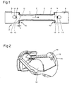
- the body 11 and the displacement body 14 are advantageously made as a single part, as shown by way of example in FIG. 2 in a perspective view. This part can be inserted laterally into the inlet or outlet connection 3 or 4 (FIG. 1), whereby it snaps into the housing 2 (FIG. 1) and is thus immovably fixed.
- Two protruding lugs 15 ensure the axial fixation of the measuring tube 6.
- Further guide elements 16 ensure the radial mounting of the measuring tube. 6
- Fig. 3 shows in detail how the body 11 can store the measuring tube 6 axially.
- the measuring tube 6 either has bevelled ends (FIG. 3) or is slightly widened towards the ends (FIG. 4).
- the measuring tube 6 is sealed radially by an O-ring in the intermediate part 5.
- the body 11 does not cover the front edge of the measuring tube 6 except for the two narrow lugs 15.
- additional surfaces in the inlet and in the outlet 3 and 4 are covered with ultrasound-absorbing material.
- the surface 12 of the body 11 facing the ultrasonic transducer 8 is oriented such that ultrasonic waves radiated by the ultrasonic transducer 8 and reflected by the surface 12 no longer impact the ultrasonic transducer 8. It has been found that this requirement is met when the surface 12 is approximately parallel to the surface 13 of the ultrasonic transducer 8, i. is designed approximately perpendicular to the axial direction 7.
- the displacement body 14 with the integrated body 11 is preferably designed such that it can be used in a flowmeter 1 with the measuring tube 6 or in a flowmeter 1 without measuring tube 6.
- a nominal flow of 0.6 m 3 / h and a designed for a nominal flow of 1.5 m 3 / h Duch flow meter 1 can be realized, which differ only in whether the measuring tube 6 is used or not.
- the ultrasonic transducer 8 (and also the ultrasonic transducer 9) is mounted laterally by means of a flange on the housing 2 of the flow meter 1.
- a mirror 17 made of stainless steel is used for deflecting the ultrasonic pulses emitted by the ultrasonic transducer 8.
- the mirror 17 is held by a plastic carrier 18.
- the plastic carrier 18 is inserted laterally into the inlet nozzle 3, wherein at least two latching noses of the plastic carrier 18 snap into a circumferential groove 19 of the housing 2.
- the plastic carrier 18 further comprises one or two pins 20 which engage in recesses of the housing 2 designed in such a way that the position of the mirror 17 is unambiguous and immovable.
- the plastic support 18 optionally limits the axial bearing of the measuring tube 6, which in turn is sealed with an O-ring in the housing 2.
- the body 11 for covering the step 10 is part of the plastic carrier 18.
- the plastic carrier 18 advantageously covers the entire interior of the inlet or outlet nozzle 3 and 4, respectively. This design of the housing 2 and of the plastic carrier 18 offers the advantages that the housing 2 can be made in a cost effective manner from pressed brass and that the plastic support 18 easily covers all parts of the housing 2, where unwanted reflections of the ultrasound could arise, coated with ultrasound-absorbing material.
- the plastic carrier 18 also serves as a displacement body to minimize the flow resistance.
- the plastic carrier 18 with the integrated body 11 is here also preferably designed such that it can be used in a flow meter 1 with a measuring tube 6 or in a flow meter 1 without measuring tube 6.
- a nominal flow of 0.6 m 3 / h and a designed for a nominal flow of 1.5 m 3 / h Duch flow meter 1 can be realized, which differ only in whether the measuring tube 6 is used or not.
- the lugs 15 and the guide elements 16 are preferably arranged one above the other (not next to one another as shown) and dimensioned so small that they do not lead to pressure loss even in the Duch flow meter 1 without measuring tube 6 contribute.
Landscapes
- Physics & Mathematics (AREA)
- Electromagnetism (AREA)
- Fluid Mechanics (AREA)
- General Physics & Mathematics (AREA)
- Measuring Volume Flow (AREA)
Description
- Die Erfindung betrifft einen Ultraschall-Durchflussmesser der im Oberbegriff des Anspruchs 1 genannten Art.
- Solche Durchflussmesser eignen sich zur Erfassung von Strömungsgeschwindigkeiten und darauf aufbauend zur Erfassung von Durchflussmengen und in Kombination mit Temperaturdifferenzmessungen zur Wärmeverbrauchserfassung und -verrechnung.
- Aus der schweizerischen Patentschrift
CH 670 156 - Aus der internationalen Patentanmeldung
WO 86/02723 - Der Erfindung liegt die Aufgabe zugrunde, einen Ultraschall-Durchflussmesser vorzuschlagen, der bereits bei kleinen Durchflussmengen eine grosse Dynamik und eine hohe Genauigkeit erreicht und dessen Druckverlust möglichst gering ist.
- Die Erfindung besteht in den im Anspruch 1 angegebenen Merkmalen. Vorteilhafte Ausgestaltungen ergeben sich aus den abhängigen Ansprüchen.
- Die Erfindung benützt ein rohrförmiges Gehäuse mit einem Einlassstutzen, einem Zwischenteil und einem Auslassstutzen, die vom Medium in annähernd gleicher Richtung durchströmt werden. Im Einlassstutzen und im Auslassstutzen ist je ein Ultraschallwandler angeordnet. Im Zwischenteil ist zwischen den beiden Ultraschallwandlern fakultativ ein Messrohr angeordnet, in dem zugleich die Ultraschallmessstrecke gebildet ist. Das Messrohr dient zur Erhöhung der Strömungsgeschwindigkeit. Sein Querschnitt ist so klein bemessen, dass bei einer vorgegebenen minimalen zu messenden Durchflussrate zwischen einem stromaufwärts und einem stromabwärts geschickten Ultraschallimpuls eine Laufzeitdifferenz resultiert, die mit einer vorgegebenen Genauigkeit messbar ist. Für die Ultraschallimpulse wirkt das Messrohr als Wellenleiter, wie es in der europäischen Patentschrift
EP 451 355 - Um zu vermeiden, dass ein Teil des von einem Ultraschallwandler in der Sendephase abgestrahlten Ultraschallimpulses irgendwo am Gehäuse reflektiert werden und während der nachfolgenden Empfangsphase wieder auf den Ultraschallwandler auftreffen und sich dabei dem vom anderen Ultraschallwandler abgestrahlten Ultraschallimpuls überlagern, sind beim Übergang vom Einlass- bzw. Auslassstutzen zur Ultraschallmessstrecke, wo sich der Innendurchmesser ändert, die Innenflächen mit ultraschallabsorbierendem Material verkleidet. Aus strömungstechnischen Überlegungen wäre zu erwarten, dass der Übergang vom Einlass- bzw. Auslassstutzen auf das Messrohr zur Erziehlung eines möglichst geringen Druckverlustes möglichst stromlinienförmig, d.h. ohne Ecken und Kanten auszubilden ist. Gemäss der Erfindung ist es jedoch möglich, sprunghafte, d.h. nicht stromlinienförmige Änderungen des Innendurchmessers vorzunehmen, ohne dass dadurch der Druckverlust merklich vergrössert wird. Die Verkleidung der so entstehenden Stufen erfolgt dahingehend, dass der vom Ultraschallwandler abgestrahlte Ultraschall, der frontal auf die Verkleidung auftrifft und der nicht absorbiert wird, in eine Richtung reflektiert wird, die am Ultraschallwandler vorbeigeht.
- Nachfolgend werden Ausführungsbeispiele der Erfindung anhand der Zeichnung näher erläutert.
- Es zeigen:
- Fig. 1
- einen Durchflussmesser mit einem Messrohr,
- Fig. 2
- einen Verdrängungskörper mit einem Verkleidungsstück,
- Fig. 3
- Details eines Durchflussmessers mit Messrohr, und
- Fig. 4
- Details eines Durchflussmessers mit Messrohr und mit Spiegeln.
- Die Fig. 1 zeigt im Längsschnitt einen Durchflussmesser 1 zur Bestimmung der Menge eines durch ein Rohrsystem strömenden Mediums wie beispielsweise Wasser, Öl oder Gas. Sein Gehäuse 2 weist einen Einlassstutzen 3 und einen Auslassstutzen 4 auf, die durch ein Zwischenteil 5 verbunden sind. Im Zwischenteil 5 ist, fakultativ, ein Messrohr 6 eingesetzt. Die Flüssigkeit durchströmt den Einlassstutzen 3, gegebenenfalls das Messrohr 6 bzw. das Zwischenteil 5 und den Auslassstutzen 4 in einer im wesentlichen gleichen, durch einen Pfeil dargestellten axialen Richtung 7. Der Einlassstutzen 3 und der Auslassstutzen 4 weisen ein Aussengewinde auf. Im Einlass- und im Auslassstutzen 3, 4 sind Ultraschallwandler 8 bzw. 9 angeordnet, die in und entgegen der Strömungsrichtung gerichtete Ultraschallimpulse abstrahlen. Im Zwischenteil 5 ist daher zwischen den beiden Ultraschallwandlern 8 und 9 eine Ultraschallmessstrecke gebildet. Die Ultraschallwandler 8 und 9 senden jeweils gleichzeitig einen aus mehreren Ultraschallwellenzügen bestehenden Ultraschallimpuls und empfangen anschliessend den vom anderen Ultraschallwandler 9 bzw. 8 gesendeten, die Ultraschallmessstrecke durcheilt habenden Ultraschallimpuls.
- Der Innendurchmesser des Einlassstutzens 3 ist grösser als der Innendurchmesser des Zwischenteils 5 oder des Messrohres 6. Der Übergang vom Einlassstutzen 3 auf das Zwischenteil 5 bzw. das Messrohr 6 ist nun derart auszubilden, dass die von den Ultraschallwandlern 8 und 9 abgestrahlten Ultraschallimpulse die Ultraschallmessstrecke möglichst direkt durcheilen, d.h. ohne dass infolge von Reflexionen Störimpulse entstehen, die sich dem zu empfangenden Ultraschallimpuls unerwünschterweise überlagern. Beim Übergang vom Einlass- bzw. Auslassstutzen 3 bzw. 4 zur Ultraschallmessstrecke sind deshalb sprunghafte Änderungen des Innendurchmessers vorgesehen, die zudem mit ultraschallabsorbierendem Material verkleidet sind.
- Der Übergang vom Einlassstutzen 3 auf das Zwischenteil 5 bzw. das Messrohr 6 ist also gemäss der Erfindung nicht stromlinienförmig ausgebildet, sondern mit einer Stufe 10. Einerseits weist das Gehäuse 2 eine Stufe 10 auf, andererseits ist diese Stufe 10 mit einem Körper 11 aus ultraschallabsorbierendem Material verkleidet, wobei der Körper 11 den stufenförmigen Übergang im wesentlichen erhält. Der Körper 11 weist demnach eine dem entsprechenden Ultraschallwandler 8 oder 9 zugewandte Fläche 12 auf, die etwa parallel zur Oberfläche 13 des Ultraschallwandlers und somit annähernd senkrecht zur axialen Richtung 7 ist. Als Material für den Körper 11 erweist sich PVDF (Polyvinylidenfluorid) als besonders vorteilhaft, da bei diesem Material eine Dicke d der Fläche 12 von etwa 1.5 mm bereits genügt, um die Reflexionen derart zu mindern, dass eine Erhöhung der Dicke d keine merkliche Verbesserung mehr bringt. Die Stufe 10 lässt sich aufeinfache Weise, beispielsweise durch Fräsen, im Gehäuse 2 anbringen.
- Wenn der Ultraschallwandler 8 einen Ultraschallimpuls sendet, dann breiten sich im Medium Ultraschallwellen aus, wovon ein geringer Anteil auf den Körper 11 auftrifft. Die auf den Körper 11 auftreffenden Ultraschallwellen dringen teilweise in diesen ein, teilweise werden sie reflektiert. Die Energie der eingedrungenen Ultraschallwellen wird zu einem grossen Teil absorbiert. Die reflektierten Ultraschallwellen werden nun in eine Richtung reflektiert, die am Ultraschallwandler 8 vorbeigeht, da die reflektierten Ultraschallwellen an der Fläche 12 des Körpers 11 wie an einem Spiegel reflektiert werden.
- Zur Minimierung des Druckabfalles sind die Ultraschallwandler 8 und 9 fakultativ mit einem Verdrängungskörper 14 verkleidet. Der Körper 11 und der Verdrängungskörper 14 sind mit Vorteil als ein einziges Teil gefertigt, wie es beispielhaft in der Fig. 2 in perspektivischer Darstellung gezeigt ist. Dieses Teil ist seitlich in den Einlass- oder Auslassstutzen 3 bzw. 4 (Fig. 1) einführbar, wobei es im Gehäuse 2 (Fig. 1) einschnappt und damit unverrückbar fixiert ist. Zwei vorstehende Nasen 15 gewährleisten die axiale Fixierung des Messrohres 6. Weitere Führungselemente 16 gewährleisten die radiale Lagerung des Messrohres 6.
- Die Fig. 3 zeigt im Detail wie der Körper 11 das Messrohr 6 axial lagern kann. Das Messrohr 6 weist entweder angeschrägte Enden auf (Fig. 3) oder ist gegen die Enden leicht aufgeweitet (Fig. 4). Mit Vorteil ist das Messrohr 6 durch einen O-Ring radial im Zwischenteil 5 abgedichtet. Der Körper 11 überdeckt die Stirnkante des Messrohres 6 mit Ausnahme der zwei schmalen Nasen 15 nicht. Fakultativ sind weitere Flächen im Einlass- und im Auslassstutzen 3 bzw. 4 mit ultraschallabsorbierendem Material verkleidet. Dem Vorteil der besseren Unterdrückung unerwünschter Ultraschallreflexionen steht der Nachteil gegenüber, dass die Verkleidung den wirksamen Querschnitt verkleinert, was zu einem höheren Druckverlust führt.
- Die dem Ultraschallwandler 8 zugewandte Fläche 12 des Körpers 11 ist derart ausgerichtet, dass vom Ultraschallwandler 8 abgestrahlte und an der Fläche 12 reflektierte Ultraschallwellen nicht mehr auf den Ultraschallwandler 8 auftreffen. Es hat sich gezeigt, dass diese Anforderung erfüllt ist, wenn die Fläche 12 annähernd parallel zur Oberfläche 13 des Ultraschallwandlers 8, d.h. annähernd senkrecht zur axialen Richtung 7 ausgestaltet ist.
- Der Verdrängungskörper 14 mit dem integrierten Körper 11 ist vorzugsweise derart ausgebildet, dass er in einem Duchflussmesser 1 mit dem Messrohr 6 oder in einem Duchflussmesser 1 ohne Messrohr 6 eingesetzt werden kann. Somit lassen sich z.B. ein für einen Nenndurchfluss von 0.6 m3/h und ein für einen Nenndurchfluss von 1.5 m3/h ausgelegter Duchflussmesser 1 realisieren, die sich nur darin unterscheiden, ob das Messrohr 6 eingesetzt ist oder nicht.
- Die Fig. 4 zeigt eine Lösung, bei der der Ultraschallwandler 8 (und auch der Ultraschallwandler 9) seitlich mittels eines Flansches am Gehäuse 2 des Durchflussmessers 1 angebracht ist. Zur Umlenkung der vom Ultraschallwandler 8 abgestrahlten Ultraschallimpulse dient ein Spiegel 17 aus nichtrostendem Stahl. Der Spiegel 17 ist von einem Kunststoffträger 18 gehalten. Bei der Montage wird der Kunststoffträger 18 seitlich in den Einlassstutzen 3 eingeführt, wobei mindestens zwei Rastnasen des Kunststoffträgers 18 in eine umlaufende Nut 19 des Gehäuses 2 einschnappen. Der Kunststoffträger 18 weist weiter ein oder zwei Zapfen 20 auf, die in derart gestaltete Ausnehmungen des Gehäuses 2 eingreifen, dass die Lage des Spiegels 17 eindeutig und unverrückbar ist. Der Kunststoffträger 18 begrenzt gegebenenfalls die axiale Lagerung des Messrohres 6, das seinerseits mit einem O-Ring im Gehäuse 2 abgedichtet ist. Der Körper 11 zur Verkleidung der Stufe 10 ist Teil des Kunststoffträgers 18. Der Kunststoffträger 18 verkleidet mit Vorteil den gesamten Innenraum des Einlass- oder Auslassstutzens 3 bzw. 4. Diese Ausbildung des Gehäuses 2 und des Kunststoffträgers 18 bietet die Vorteile, dass das Gehäuse 2 auf kostengünstige Weise aus Pressmessing hergestellt werden kann und dass der Kunststoffträger 18 problemlos alle Stellen des Gehäuses 2, an denen unerwünschte Reflexionen des Ultraschalls entstehen könnten, mit ultraschallabsorbierendem Material verkleidet. Der Kunststoffträger 18 dient auch als Verdrängungskörper zur Minimierung des Strömungswiderstandes.
- Der Kunststoffträger 18 mit dem integrierten Körper 11 ist auch hier vorzugsweise derart ausgebildet, dass er in einem Duchflussmesser 1 mit einem Messrohr 6 oder in einem Duchflussmesser 1 ohne Messrohr 6 eingesetzt werden kann. Somit lassen sich z.B. ein für einen Nenndurchfluss von 0.6 m3/h und ein für einen Nenndurchfluss von 1.5 m3/h ausgelegter Duchflussmesser 1 realisieren, die sich nur darin unterscheiden, ob das Messrohr 6 eingesetzt ist oder nicht. Die Nasen 15 und die Führungselemente 16 (Fig. 2) sind vorzugsweise übereinander angeordnet (nicht nebeneinander wie dargestellt) und so klein bemessen, dass sie auch beim Duchflussmesser 1 ohne Messrohr 6 nicht zum Druckverlust beitragen.
Claims (3)
- Durchflussmesser (1) mit einem Gehäuse (2) mit einem Einlassstutzen (3) und einem Auslassstutzen (4), zwischen denen eine von einem Medium in einer axialen Richtung (7) durchströmte Ultraschallmessstrecke gebildet ist, wobei im Einlassstutzen (3) und im Auslassstutzen (4) je ein Ultraschallwandler (8 bzw. 9) oder ein von einem Ultraschallwandler (8 bzw. 9) beschallter Spiegel (17) zur Beschallung der Ultraschallmessstrecke angeordnet ist, dadurch gekennzeichnet, dass das Gehäuse (2) beim Übergang vom Einlass- bzw. Auslassstutzen zur Ultraschallmessstrecke inwendig mit einem Körper (11) aus ultraschallabsorbierenden Material verkleidet ist, der eine dem entsprechenden Ultraschallwandler (8 bzw. 9) zugewandte Fläche (12) aufweist, die im wesentlichen senkrecht zur axialen Richtung (7) ausgebildet ist.
- Durchflussmesser (1) nach Anspruch 1, dadurch gekennzeichnet, dass die Ultraschallwandler (8 bzw. 9) bzw. die Spiegel (17) mit einem Verdrängungskörper (14) versehen sind und dass der Verdrängungskörper (14) und der Körper (11) als ein Teil gebildet sind.
- Durchflussmesser nach Anspruch 1 oder 2, dadurch gekennzeichnet, dass der Körper (11) aus PVDF besteht.
Priority Applications (4)
| Application Number | Priority Date | Filing Date | Title |
|---|---|---|---|
| DE59712855T DE59712855D1 (de) | 1997-08-14 | 1997-08-14 | Ultraschall-Durchflussmesser |
| DK97114097T DK0897102T3 (da) | 1997-08-14 | 1997-08-14 | Ultralyd-gennemströmningsmåler |
| EP19970114097 EP0897102B1 (de) | 1997-08-14 | 1997-08-14 | Ultraschall-Durchflussmesser |
| PL98327982A PL187726B1 (pl) | 1997-08-14 | 1998-08-13 | Przepływomierz ultradźwiękowy |
Applications Claiming Priority (1)
| Application Number | Priority Date | Filing Date | Title |
|---|---|---|---|
| EP19970114097 EP0897102B1 (de) | 1997-08-14 | 1997-08-14 | Ultraschall-Durchflussmesser |
Publications (2)
| Publication Number | Publication Date |
|---|---|
| EP0897102A1 EP0897102A1 (de) | 1999-02-17 |
| EP0897102B1 true EP0897102B1 (de) | 2007-06-27 |
Family
ID=8227221
Family Applications (1)
| Application Number | Title | Priority Date | Filing Date |
|---|---|---|---|
| EP19970114097 Expired - Lifetime EP0897102B1 (de) | 1997-08-14 | 1997-08-14 | Ultraschall-Durchflussmesser |
Country Status (4)
| Country | Link |
|---|---|
| EP (1) | EP0897102B1 (de) |
| DE (1) | DE59712855D1 (de) |
| DK (1) | DK0897102T3 (de) |
| PL (1) | PL187726B1 (de) |
Cited By (2)
| Publication number | Priority date | Publication date | Assignee | Title |
|---|---|---|---|---|
| DE102008003404A1 (de) | 2007-01-15 | 2008-07-17 | Georg Zwisler | Verfahren zur Dekoration der Oberflächen von Werkstücken |
| CN101476911B (zh) * | 2004-03-01 | 2013-03-20 | 流速测量计有限公司 | 用于确定流动介质的流量的超声波计数器 |
Families Citing this family (15)
| Publication number | Priority date | Publication date | Assignee | Title |
|---|---|---|---|---|
| DE10235032B3 (de) | 2002-07-31 | 2004-04-08 | Hydrometer Gmbh | Verfahren zum Betrieb eines Ultraschall-Durchflußmessers und entsprechender Ultraschall-Durchflußmesser |
| DE10235060B4 (de) * | 2002-07-31 | 2006-11-30 | Hydrometer Gmbh | Gekrümmte Ultraschall-Messstrecke |
| DK1493998T3 (da) | 2003-06-13 | 2017-02-13 | Diehl Metering Gmbh | Ultralydsmåler til bestemmelse af gennemstrømningsmængden af et strømmende medium |
| EP2278281B1 (de) * | 2009-07-03 | 2018-03-07 | Kamstrup A/S | Durchflussmesser mit einem im Gehäuse eingerasteten Umlenkspiegelhalter |
| CN102831717A (zh) * | 2012-08-27 | 2012-12-19 | 曲宝源 | 预付费小口径超声波智能水表 |
| EP3798583B1 (de) * | 2013-01-29 | 2023-03-08 | Itron Global SARL | Wandlerträger für einen ultraschall-durchflussmesser und ultraschall-durchflussmesser |
| DE102014019424B4 (de) * | 2014-12-20 | 2016-07-21 | Diehl Metering Gmbh | Ultraschallzähler |
| CN107949408B (zh) | 2015-08-28 | 2021-01-29 | 克里斯医疗系统股份有限公司 | 具有吸收器的流量传感器系统 |
| CA3044652C (en) | 2015-08-28 | 2023-08-08 | Crisi Medical Systems, Inc. | Flow sensor system including spring contacts |
| WO2017040202A1 (en) | 2015-08-28 | 2017-03-09 | Crisi Medical Systems, Inc. | Flow sensor system including transmissive connection |
| EP3341045B1 (de) | 2015-08-28 | 2020-12-30 | Crisi Medical Systems, Inc. | Durchflusssensorsystem mit verbindungsanordnung |
| CN109219457B (zh) | 2016-06-17 | 2021-10-29 | 贝克顿·迪金森公司 | 用于润湿流体端口的内部流体路径表面以增进超声信号传输的方法和设备 |
| ES2955308T3 (es) | 2017-06-19 | 2023-11-30 | Becton Dickinson Co | Válvula de cebado para inducir un perfil adecuado de presión y flujo y mejorar la disponibilidad de un sensor |
| CA3105189A1 (en) | 2018-07-06 | 2020-01-09 | Becton, Dickinson And Company | Flow sensor and method for adjusting fluid flow measurement |
| JP7710451B2 (ja) | 2020-01-22 | 2025-07-18 | ベクトン・ディキンソン・アンド・カンパニー | カプラおよびフローチューブを超音波流量計に接合する装置および方法 |
Family Cites Families (4)
| Publication number | Priority date | Publication date | Assignee | Title |
|---|---|---|---|---|
| CH655574B (de) * | 1982-03-01 | 1986-04-30 | ||
| JPS59190621A (ja) * | 1983-04-14 | 1984-10-29 | Honda Motor Co Ltd | 超音波流量計 |
| NL8403222A (nl) * | 1984-10-23 | 1986-05-16 | Nedap Nv | Methode ter vermindering van ongewenste echo's in ultrasone stroomsnelheidsmeters. |
| CH670156A5 (de) * | 1986-06-17 | 1989-05-12 | Landis & Gyr Gmbh |
-
1997
- 1997-08-14 EP EP19970114097 patent/EP0897102B1/de not_active Expired - Lifetime
- 1997-08-14 DK DK97114097T patent/DK0897102T3/da active
- 1997-08-14 DE DE59712855T patent/DE59712855D1/de not_active Expired - Lifetime
-
1998
- 1998-08-13 PL PL98327982A patent/PL187726B1/pl not_active IP Right Cessation
Cited By (2)
| Publication number | Priority date | Publication date | Assignee | Title |
|---|---|---|---|---|
| CN101476911B (zh) * | 2004-03-01 | 2013-03-20 | 流速测量计有限公司 | 用于确定流动介质的流量的超声波计数器 |
| DE102008003404A1 (de) | 2007-01-15 | 2008-07-17 | Georg Zwisler | Verfahren zur Dekoration der Oberflächen von Werkstücken |
Also Published As
| Publication number | Publication date |
|---|---|
| DE59712855D1 (de) | 2007-08-09 |
| DK0897102T3 (da) | 2007-10-29 |
| PL327982A1 (en) | 1999-02-15 |
| EP0897102A1 (de) | 1999-02-17 |
| PL187726B1 (pl) | 2004-09-30 |
Similar Documents
| Publication | Publication Date | Title |
|---|---|---|
| EP0897102B1 (de) | Ultraschall-Durchflussmesser | |
| EP0897101B1 (de) | Ultraschall-Durchflussmesser | |
| EP0890826B1 (de) | Ultraschall-Durchflussmesser mit Messeinsatz aus Kunststoff | |
| EP2172657B1 (de) | Strömungsrichter für ein Durchflussmessgerät, insbesondere ein Ultraschallmessgerät | |
| EP2300786B1 (de) | Ultraschallsensor eines messsystems zur bestimmung und/oder überwachung des durchflusses eines messmediums durch ein messrohr | |
| EP0681162A1 (de) | Messwertgeber zur Messung von Flüssigkeitsströmungen mit Ultraschall | |
| EP2988103B1 (de) | Durchflussmesser mit einem in ein gehäuse eingesetzten messeinsatz | |
| EP1891400A1 (de) | Ultraschallmessstrecke aus kunststoff und entsprechendes messverfahren | |
| EP0559938A1 (de) | Durchflussmesseinrichtung für flüssige Medien nach dem Ultraschall-Laufzeitprinzip | |
| EP1978337B1 (de) | Ultraschallzähler zur Bestimmung der Durchflussmenge eines strömenden Mediums | |
| DE102007011547B4 (de) | Fluidzählanordnung | |
| EP3677877A1 (de) | Messrohr und ultraschall-durchflussmengenmesser | |
| DE3518266A1 (de) | Stroemungsmesser | |
| DE102008013224A1 (de) | Messsystem und Verfahren zur Bestimmung und/oder Überwachung eines Durchflusses eines Messmediums durch ein Messrohr | |
| EP1096237A2 (de) | Ultraschall-Durchflussmessgerät | |
| EP0790490B1 (de) | Ultraschall-Messwertgeber zur Bestimmung der Durchflussmenge einer strömenden Flüssigkeit | |
| DE19533814C2 (de) | Vorrichtung zur Ultraschall-Durchflußmessung | |
| DE10235034B4 (de) | Durchflußmesser | |
| DE9420760U1 (de) | Durchflussmesser | |
| DE102010063789A1 (de) | Ultraschall-Durchflussmessgerät | |
| EP2317288B1 (de) | Durchflussmengenmesseinrichtung mit Spiegel am Messrohrende | |
| CH669039A5 (de) | Durchflussmesser. | |
| DE202019003218U1 (de) | Messrohr und Ultraschall-Durchflussmengenmesser | |
| DE10235033B4 (de) | Durchflußmesser | |
| EP1387149B1 (de) | Ultraschall-Durchflussmesser sowie Verfahren zum Betrieb desselben |
Legal Events
| Date | Code | Title | Description |
|---|---|---|---|
| PUAI | Public reference made under article 153(3) epc to a published international application that has entered the european phase |
Free format text: ORIGINAL CODE: 0009012 |
|
| AK | Designated contracting states |
Kind code of ref document: A1 Designated state(s): CH DE DK FI LI SE |
|
| AX | Request for extension of the european patent |
Free format text: LT |
|
| 17P | Request for examination filed |
Effective date: 19990817 |
|
| AKX | Designation fees paid |
Free format text: CH DE DK FI LI SE |
|
| AXX | Extension fees paid |
Free format text: LT PAYMENT 19990817 |
|
| RAP1 | Party data changed (applicant data changed or rights of an application transferred) |
Owner name: SIEMENS AKTIENGESELLSCHAFT |
|
| RAP1 | Party data changed (applicant data changed or rights of an application transferred) |
Owner name: LANDIS+GYR GMBH |
|
| GRAP | Despatch of communication of intention to grant a patent |
Free format text: ORIGINAL CODE: EPIDOSNIGR1 |
|
| GRAS | Grant fee paid |
Free format text: ORIGINAL CODE: EPIDOSNIGR3 |
|
| GRAA | (expected) grant |
Free format text: ORIGINAL CODE: 0009210 |
|
| AK | Designated contracting states |
Kind code of ref document: B1 Designated state(s): CH DE DK FI LI SE |
|
| AX | Request for extension of the european patent |
Extension state: LT |
|
| REG | Reference to a national code |
Ref country code: CH Ref legal event code: EP |
|
| REF | Corresponds to: |
Ref document number: 59712855 Country of ref document: DE Date of ref document: 20070809 Kind code of ref document: P |
|
| REG | Reference to a national code |
Ref country code: SE Ref legal event code: TRGR |
|
| REG | Reference to a national code |
Ref country code: DK Ref legal event code: T3 |
|
| LTIE | Lt: invalidation of european patent or patent extension |
Effective date: 20070627 |
|
| PLBE | No opposition filed within time limit |
Free format text: ORIGINAL CODE: 0009261 |
|
| STAA | Information on the status of an ep patent application or granted ep patent |
Free format text: STATUS: NO OPPOSITION FILED WITHIN TIME LIMIT |
|
| 26N | No opposition filed |
Effective date: 20080328 |
|
| PGFP | Annual fee paid to national office [announced via postgrant information from national office to epo] |
Ref country code: CH Payment date: 20080630 Year of fee payment: 12 |
|
| PGFP | Annual fee paid to national office [announced via postgrant information from national office to epo] |
Ref country code: FI Payment date: 20080825 Year of fee payment: 12 |
|
| PGFP | Annual fee paid to national office [announced via postgrant information from national office to epo] |
Ref country code: SE Payment date: 20080825 Year of fee payment: 12 |
|
| REG | Reference to a national code |
Ref country code: CH Ref legal event code: PL |
|
| PG25 | Lapsed in a contracting state [announced via postgrant information from national office to epo] |
Ref country code: LI Free format text: LAPSE BECAUSE OF NON-PAYMENT OF DUE FEES Effective date: 20090831 Ref country code: FI Free format text: LAPSE BECAUSE OF NON-PAYMENT OF DUE FEES Effective date: 20090814 Ref country code: CH Free format text: LAPSE BECAUSE OF NON-PAYMENT OF DUE FEES Effective date: 20090831 |
|
| PG25 | Lapsed in a contracting state [announced via postgrant information from national office to epo] |
Ref country code: SE Free format text: LAPSE BECAUSE OF NON-PAYMENT OF DUE FEES Effective date: 20090815 |
|
| PGFP | Annual fee paid to national office [announced via postgrant information from national office to epo] |
Ref country code: DK Payment date: 20150825 Year of fee payment: 19 |
|
| PGFP | Annual fee paid to national office [announced via postgrant information from national office to epo] |
Ref country code: DE Payment date: 20151023 Year of fee payment: 19 |
|
| REG | Reference to a national code |
Ref country code: DE Ref legal event code: R119 Ref document number: 59712855 Country of ref document: DE |
|
| REG | Reference to a national code |
Ref country code: DK Ref legal event code: EBP Effective date: 20160831 |
|
| PG25 | Lapsed in a contracting state [announced via postgrant information from national office to epo] |
Ref country code: DK Free format text: LAPSE BECAUSE OF NON-PAYMENT OF DUE FEES Effective date: 20160831 Ref country code: DE Free format text: LAPSE BECAUSE OF NON-PAYMENT OF DUE FEES Effective date: 20170301 |