EP0896426A1 - Method for simulating a nonlinear amplifier with envelope memory - Google Patents
Method for simulating a nonlinear amplifier with envelope memory Download PDFInfo
- Publication number
- EP0896426A1 EP0896426A1 EP98401958A EP98401958A EP0896426A1 EP 0896426 A1 EP0896426 A1 EP 0896426A1 EP 98401958 A EP98401958 A EP 98401958A EP 98401958 A EP98401958 A EP 98401958A EP 0896426 A1 EP0896426 A1 EP 0896426A1
- Authority
- EP
- European Patent Office
- Prior art keywords
- amplitude
- frequency
- signal
- components
- input
- Prior art date
- Legal status (The legal status is an assumption and is not a legal conclusion. Google has not performed a legal analysis and makes no representation as to the accuracy of the status listed.)
- Withdrawn
Links
Images


Classifications
-
- H—ELECTRICITY
- H03—ELECTRONIC CIRCUITRY
- H03F—AMPLIFIERS
- H03F1/00—Details of amplifiers with only discharge tubes, only semiconductor devices or only unspecified devices as amplifying elements
- H03F1/32—Modifications of amplifiers to reduce non-linear distortion
- H03F1/3241—Modifications of amplifiers to reduce non-linear distortion using predistortion circuits
Definitions
- the present invention relates to the field of response simulation in signal from non-linear amplifiers and relates to a signal simulation system response of a non-linear amplifier with a memory effect.
- An application of such a system is the simulation of amplification high efficiency microwave, in particular in class AB, B or C of amplification and more particularly the simulation of response of power amplifiers in the state solid, SSPA type, and amplifiers based on wave tubes progressive, TOP or TWT type, used in transmission links by terrestrial or satellite radio beam.
- Such amplifying devices exhibit a non-linear response characteristic.
- Figure 1 illustrates an example of an input-output response curve ANL non-linear amplifier.
- the curve giving the output signal level g of the amplifier ANL as a function of the input signal level x is typically bent at high amplitudes A of the input signal x, due to phenomena of saturation.
- gain is not constant depending on the input signal level x, we speak of amplifier operating in a non-linear regime or more simply in non-linear amplification.
- Amplifiers without memory exhibit strong non-linearity in amplitude and less phase distortion.
- the response characteristic input / output of an amplifier without ANL memory can then be reduced, as illustrated in figure 1, with a single curve g (x).
- a (t) represents the envelope of the input signal, which is defined by the limits in amplitude in which the sinusoidal signal x evolves, the envelope varying according to the time.
- FIG. 3 illustrates a timing diagram of a signal x (t) having an envelope A constant.
- g (t) C (A (t)). cos (2 ⁇ .f 0 .t + ⁇ (t))
- C (A) is the Chebyshev transform of the input / output response curve g (x).
- the response of a non-linear ANL amplifier without memory to a signal x modulated can therefore be modeled and simulated simply by a single curve C (A), an example of which is illustrated in solid lines in FIG. 6A.
- A Such a curve giving the output amplitude C as a function of the input amplitude A is called the amplitude non-linearity and noted abbreviated AM / AM curve.
- Figure 2 illustrates a response characteristic of a non-linear amplifier with memory ANLAM, on which a phenomenon of hysteresis appears caused by memory effect.
- the rise curves m and m ' hysteresis do not overlap when the respective amplitudes A and A 'of the signal input x are different.
- the variation in the memorization time linked to the variation amplitude prevents the curves m and m 'from overlapping.
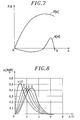
- Figure 7 illustrates an example of curves P (A) and Q (A) equivalent to curves C (A) and ⁇ (A) of Figures 6A and 6B.
- the known quasi-memoryless amplifier response simulation models generally prefer to use features as a pair of curves P (A) and Q (A) rather than as a pair of curves C (A) and ⁇ (A), well that these pairs of curves are strictly equivalent.
- a known principle of non-linear amplifier simulation consists in precharacterize the amplifier produced on a test bench, precharacterization being performed with a signal of determined frequency and amplitude, in order to simulate then the response to a signal of any frequency and amplitude.
- a single frequency signal f 0 taking different amplitudes A ', A'', A ′′′ is applied to the amplifier tested to obtain its characteristics, illustrated for example in FIG. 6 or 7.
- HB Poza's simulator stores only a pair of AM / AM and AM / PM curves, for example the pair of curves obtained at the frequency f 0 , and reconstructs the other pairs of curves (not stored) corresponding to the other frequencies f 0 - , f 0 + or at intermediate frequencies.
- An unstored curve is deduced simply by translating the stored curve of a suitable vector.
- the simulator calculates the components along the axis (A) and along the axis (C) or ( ⁇ ) of the translation vector to best approximate the frequency curve f 0 , shown in solid line in FIG. 6A or 6B, of the frequency curve f 0 - or f 0 + , shown in dotted lines.
- Another disadvantage of such a system is that it does not simulate the response from a memory amplifier.
- FIG. 9 illustrates another known system of simulation, according to the model of A.A.M. Saleh, described in an article titled “Frequency-independent and frequency-dependent models of TWTA Amplifiers "published in November 1981 in the review” IEEE transactions on communication ", volume com-29, n ° 11, page 1715.
- the calculation of the response to an input signal x from a quasi-memoryless non-linear amplifier is decomposed into two stages P (A, f) and Q (A, f) of calculation of two components yp and yq respective of the output signal y.
- the yp component is in phase with the signal input x, while the component yq is in phase quadrature.
- Saleh's simulation system uses characterization results from the amplifier at several frequencies f, several pairs of curves P (A) and Q (A) being established at several frequencies f to calculate transfer functions P (A, f) and Q (A, f) corresponding to each branch of calculation of the components yp and yq of the signal output y.
- Each of the transfer functions P (A, f) or Q (A, f) corresponds to the calculation of a non-linear response without memory effect, no phase shift being introduced in each of these calculation branches.
- Another disadvantage of this model is that it does not apply to memory amplifiers, the system not accounting for distortions appearing at different frequencies when the signal amplitude changes rapidly compared to the storage time constants.
- FIG. 10 illustrates the simulation system described by MT Abuelma'atti which as before comprises two branches for calculating the components in phase yp and in quadrature yq of the output signal y, each branch calculating the contribution of a series of N functions of Bessel J1 depending on the amplitude A of the input signal x, by weighting each function J1 by a coefficient ⁇ and a factor G (f) of frequency correction.
- the coefficients ⁇ n and the factors G n (f) are calculated after having established several pairs of curves P (A) and Q (A) characteristic of the non-linear amplifier, the curves being established at several test frequencies f the amplifier.
- Bessel functions are the Chebychev transforms of sinusoidal functions and that the development following Bessel functions of curves P (A) and Q (A) corresponds to a Fourier expansion following sinusoidal functions of the amplifier's non-linearity curves y (x), which elegantly suited to the sinusoidal shape of the hysteresis curves y (x), such as illustrated in figure 2.
- such a system should allow the simulation of amplification of multi-carrier signals, i.e. signals comprising several sinusoidal components of distinct frequencies.
- Figures 11-14 illustrate the appearance of the intermodulation phenomenon during non-linear amplification of a two-carrier signal.
- FIG. 11 represents a frequency diagram of input signal x two-carrier, on which we see for example, two carrier components of respective frequencies f -1 and f 1 having an equal amplitude A input.
- the two carrier frequencies f -1 and f 1 located in the useful band BU of the amplifier frequency, are separated by a frequency difference df.
- FIG. 14 represents a frequency diagram of output signal y which corresponds to ANLAM amplification with memory effect of the input signal x two-carrier in Figure 11.
- the output signal has a series of harmonics of various frequencies f and of different amplitudes C.
- the frequency of each of the intermodulation components is a integer combination of input carrier frequencies.
- Figure 15 reproduces results provided by the Abuelma'atti model which allowed an estimation of the amplitudes C -1 , C 1 , and C -3 , C 3 of output of the carrier components and the order intermodulation components 3.
- the estimation of the amplitude of the intermodulation components by the Abuelma'atti's model does not correspond well to the reality of distortion measurements intermodulation when amplifying multi-carrier microwave signals by a memory amplifier in non-linear operation with high efficiency.
- envelope memory when amplifying a multi-carrier signal.
- envelope memory when amplifying a multi-carrier signal, the envelope, defined by the positive and negative limits in amplitude of the signal, is not constant.
- FIG. 12 which illustrates the temporal evolution of the input signal x two-carrier of FIG. 11, shows for example that the envelope X (t) and -X (t) of the two-carrier signal varies very quickly and in significant proportions, whereas the amplitude A of each carrier f 1 and f -1 carrier is assumed to be constant.
- FIG. 13 which illustrates the temporal evolution of the output signal y corresponding to the previous input signal x two-carrier, thus shows that the envelope Y (t) and -Y (t) of the output signal y, then appears very distorted by the distortions intermodulation. These are referred to as the envelope memory effect. amplitude distortions of the signal by a non-linear amplifier with memory.
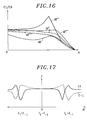
- the first effect observed is that the C1 / C3 ratio illustrated in Figure 16, comparing the amplitude C1 of carriers with respect to the amplitude C3 of the components intermodulation, varies considerably according to the frequency difference df of the carriers and according to the precise value of the amplitude A of the carriers of the input signal.
- the second effect observed is that the presence of a second carrier influences the output amplitude of the first carrier.
- FIG. 17 shows for example peaks of weakening or resonance of amplitude C1 or C-1 of output of each of the carriers of frequency f 1 or f -1 , according to the frequency difference df of the two carriers (df being equal to f 1 -f -1 ).
- the object of the invention is to provide a response simulation system by signal from a non-linear amplifier having a memory effect without them aforementioned drawbacks.
- a primary object of the invention is to obtain precise simulations of the effects of envelope memory on non-linear amplifiers.
- a particular object of the invention is to obtain precise simulations of amplification of multi-carrier signals by a non-linear memory amplifier.
- Another object of the invention is to provide a simple system for simulating response from non-linear memory amplifiers.
- the invention provides a measure dynamic characteristics of the amplifier under the conditions where distortions, that is to say with an amplitude modulated signal, which makes it possible to vary the signal envelope.
- the amplitude modulation distortions each measurement being made by modulating the input amplitude.
- These measurements of modulation distortion characteristics allow to calculate modulation transfer functions reproducing at output the amplitudes of the distortions according to the amplitudes of modulation at input.
- the amplitudes of distortions reproduced by the transfer functions modulation correct the output of direct transfer functions from a known model.
- the known models were obtained by measuring characteristics of amplitude / amplitude conversion and amplitude / phase shift conversion of the amplifier, each measurement being carried out at constant amplitude at the input, then at developing the characteristics as a result of direct transfer function.
- Modulation distortion characteristic measurements are performed more precisely with multi-carrier signals, that is to say by applying signals comprising several frequency components (carriers) at input of the non-linear amplifier, the amplified signals at the output presenting a multitude of frequency components (amplified carriers + intermodulation products).
- the amplifier has a variation in carrier gain in depending on the envelope frequency, it is planned to measure characteristics of amplitude gain for a carrier in the presence of another carrier as a function of the carrier differential.
- the means for generating harmonics of the device include preferably according to the invention a Fourier decomposition module of a signal into frequency components and / or a combinatorial module calculating the combinations frequency of intermodulation components and / or a normative module calculating an effective signal amplitude value.
- a first embodiment of the device according to the invention provides that the modulation filter has a transfer function established from characteristics of rejection of intermodulation components, so that components amplitude intermodulation calculated by the modulation filter are added to the response of the calculation module when the amplification of a multi-carrier signal is simulated by the device.
- a second embodiment of the device according to the invention provides in in addition to a filter for correcting the response of the calculation module, the filter having a transfer function established from interaction characteristics of carriers, so that the amplitude of a carrier provided by the calculation module is corrected by the correction filter when the amplification of a multi-carrier signal is simulated by the device.
- the invention advantageously applies to the simulation of response in signal from a high efficiency microwave amplifier.
- the simulation methods and device according to the invention are developed at from known models.
- the invention proposes to simulate the amplification of shape signals any and especially of signals comprising several components frequency.
- the device simulation includes means for generating harmonics in response to a multi-carrier signal.
- FIGS. 21 to 23 systematically include a block 11 or 21 or 31 for signal calculation output y according to a known model and a parallel block 12 or 22, 23 or 32 of generation of harmonics which calculates the frequencies of the components intermodulation before calculating their precise amplitude to correct the signal exit there.
- the output signal calculation blocks 11, 21 and 31 are provided for putting implement a known simulation model, for example and respectively the model non-linear without memory MNLSM by H.B. Poza, the non-linear model without Quadratic MNLSM memory of A.A.M. Saleh and the MM memory model of M.T. Abuelma'atti.
- Other models can be implemented, and the description of the implementation of the invention will be developed mainly from the model perfected by M.T. Abuelma'atti.
- the parallel structure of the MNLSM output calculation blocks or MM and Harm blocks for generating harmonics is indicative, the structure of blocks being able to be in series, and the effective realization of the blocks of calculations being of preferably done by computer programs, the blocks schematically in this case the functions of calculation subroutines.
- FIG. 23 describes the detail of an alternative embodiment of Harm means for generating harmonics and MM means for calculating the intermodulation components perfected from the simple Abuelma'atti model illustrated in FIG. 10.
- the Harm and MM modules allow the calculation of the amplitudes of intermodulation components ..., Y 010 , Y 1-11 , Y -120 , Y -111 , Y 0-12 , Y -102 , Y 20-1 , Y 2- 10 , Y 11-1 , Y 02-1 , ... when the input signal x comprises a multitude of frequency components A, B, ..., M.
- This complex embodiment of means Harm and MM is intended for the simulation of the amplification of signals of any shape, in particular of multi-carrier signals.
- Harm means for generating harmonics include an FFT filter for decomposition in Fourier series to decompose the multifrequency input signal x into frequency components of amplitude A, B, ..., M. These components are applied as input to elementary filters grouped by tables corresponding to the calculation of an intermodulation component, for example Y 010 .
- Each elementary filter has a transfer function resulting from a generalized Bessel function J on the example of the filters of FIG. 10. The formulas of the transfer functions of the filters of the table and of the generalized Bessel functions will be detailed in the developments below. -after.
- the architecture of a device according to the invention comprises means for generating harmonics, preferably with a decomposition module in Fourier series and a known simulation model.
- the envelope Y of the output signal corresponding to the bi-carrier input signal x of equations 9 and 10 comprises a series of frequency components denoted f i and amplitude denoted C i , i being a positive or negative integer.
- the order of the intermodulation components is the sum of the absolute values of the integer coefficients of combination of the carrier frequencies.
- the order 0, 1, 2 or N of a Bessel function J0, J1, J2 or JN is chosen so as to correspond to the absolute value of the integer coefficient of combination of a carrier frequency f -1 or f 1 in the frequency f i of the intermodulation component of amplitude C i .
- of each intermodulation component C i therefore corresponds to the sum of the orders 0, 1, 2 or N of the Bessel functions J0, J1, J2 or JN involved in each formula.
- n is the Bessel function of the first type and of absolute value order of n (generalization).
- FIG. 20 thus illustrates a sophisticated embodiment of MM calculation means of intermodulation components developed from these model formulas to memory.
- a determining quality factor in the design and choice of a microwave amplification system is the ratio of the amplitude C 3 of the strongest intermodulation component at output and of the amplitude C 1 at output of a carrier component.
- the rejection factor is generally expressed in power, which corresponds to the following ratio: C1 2 / C3 2 noted here P / I 2 .
- the frequency correctors G n (f i ) have a weak correction effect, the curve of the correctors G n being calculated from measurements with a single carrier, therefore without modulation of the input envelope.
- the intermodulation rejection factors P / I thus calculated do not depend on the frequency difference df of the carriers, unlike the resonance effects observed and illustrated for example in FIG. 16.
- the signal y (t) calculated according to the model of Abuelma'atti is compared to a signal z (t) comprising components intermodulation as actually measured. Such a comparison provides the value of a modulation signal u (t) which will be simulated by a modulation filter according to the invention.
- Figure 21 shows schematically a first embodiment of the device according to the invention, which includes such a modulation filter 14.
- the filter 14 has a function of transfer E (f, H) which calculates the signal u according to the input signal.
- the y signal of known model 11 is then corrected by the modulator signal u to provide a signal z which reproduces the modulation distortions actually measured.
- the modulator signal u is useful only if the signal input has an amplitude modulated envelope X. Indeed, when the input signal x is not modulated, the known model 11 has an output signal y which simulates the amplifier's response appropriately.
- the invention specifically provides for obtaining the signal envelope by taking the square of the signal standard x.
- FIG. 21 thus shows that the filter 14 receives as input the effective value X 2 (t) of the envelope of the input signal x.
- the signal z simulated according to the invention has an envelope Z which corresponds to the envelope Y of the output signal y simulated by the known model MNLSM or MM, and the modulator signal u is advantageously zero.
- E (0, A) has a zero value, since it is useless to have a modulator signal u when there is no carrier frequency difference.
- K A 2 .E (df, A)
- Equation (12) Equivalently to equation (12), we prefer here to write the envelope Y of the output signal y of the known model in the following complex and exponential form: where i is an odd integer taking all negative and positive values.
- Is : Y (t) ... + C -5 .exp (-j.5 ⁇ .df.t) + C -3 .exp (-j.3 ⁇ .df.t) + C -1 .exp (-j. ⁇ .df.t) + C 1. exp (j. ⁇ .df.t) + C 3 .exp (j.3 ⁇ .df.t) + C 5 .exp (j.5 ⁇ .df.t) + ...
- the first embodiment it is sought to modulate only the amplitude of the intermodulation components of order 3 by modifying at least the amplitude of the carrier components (order 1) calculated by the known model. This is achieved by minimizing the value of K, so that the terms KC -3 , KC 1 , KC -1 and KC 3 are negligible.
- the two central lines of equation (25) indicate that the carrier components of frequency f -1 and f 1 do indeed have an amplitude substantially equal to C -1 and C 1 , respectively, in the output signal z module.
- K
- FIG. 18 provides a diagram of the system of measurements carried out according to the invention.
- the continuity of the transfer function E (df, H) according to the amplitude H of the harmonics h at input or according to the power X 2 of the envelope of the input signal x is obtained by interpolating the discrete values from the table of values unknown K.
- the unknown values K can also be interpolated between the chosen values df ', df ", df ′′′, df" "of frequency difference df.
- a computer program preferably performs such calculations and stores the values of unknown K in the form of a matrix.
- the frequency asymmetries of the amplifier response can then be simulated by this variant of the first embodiment.
- the invention provides that the transfer function E '(df, H) of the filter 14 can be asymmetrical.
- C i the modulated components of the modulated output signal z' obtained according to this variant of the first embodiment.
- the output signal z ' is also obtained by modulating the signal y of a known model by a modulator signal u' calculated by the transfer function E 'of the filter 34 of FIG. 23. This makes it possible to distinguish the components C' i modulated according to the invention, components C i calculated by the model with no known MNLSM memory.
- the amplifier has an asymmetrical response around the carrier frequencies, it is provided according to the invention to measure intermodulation rejection characteristics, by providing for measuring the two rejection factors P / I + higher and P / I - lower for each amplitude A and frequency difference df of carriers, in order to simulate the distortions of modulation at output.
- a second embodiment of the invention makes it possible to simulate the second effect intermodulation distortion.
- the second effect observed is the variation of the gain of the carriers as a function of the envelope frequency df / 2, illustrated for example in FIG. 17.
- the invention provides for adjusting the amplitudes C 1 and C -1 of the carrier output calculated by a known model, taking into account measurements of characteristics C1 / C-1 of carrier interaction.
- the adjustment of the second embodiment is combined with the adjustment of the main intermodulation components C 3 and C- 3 provided for in the first embodiment of the invention, described above. It is also possible to provide for an adjustment of the secondary intermodulation components C 5 and C 5 .
- the adjustment is performed by correcting the output signal y, or preferably the modulated signal z or z ', by a correction signal v coming from a filter 37 having a transfer function F of correction.
- F is the correction transfer function expressed as a function of the envelope modulation frequency, i.e. the frequency difference df of amplitude A carriers at input.
- Equations 35 to 38 form a system of four equations with four unknowns K + , K - , L + , L - which is solved in a known manner.
- the resolution of the last two equations 37 and 38 provides the values of the correction unknowns L + and L - .
- Such complete measurements of amplitudes of components at the output of a amplifier comprising both component rejection measurements intermodulation of order 3 and 5 at output and carrier interaction measurements thus allow to fully simulate the signal response with distortions due to the envelope memory effect of a non-linear amplifier with memory.
- partial measures such as rejection measures C1 / C3 3 order intermodulation or C1 / C-1 carrier interaction measurements are sufficient to characterize certain intermodulation distortion effects.
- a second embodiment allows validation of the model by measurement signal-to-noise ratio in the presence of a high number of carriers whose density DSP power spectral is modeled by white noise.
- FIGS. 19A and 19B thus illustrate a frequency diagram of noise, respectively applied at the input and measured at the output of a non-linear amplifier memory to characterize it.
- white noise is applied having a DSP power spectral density of constant NP level in a band of frequency BW except in a window BH of frequency in which the noise is absent.
- This input signal although having a constant spectral density is of amplitude variable. It therefore makes it possible to measure the modulation distortions appearing in amplifier output. The distortions appear at the amplifier output under form of noise transfer in the previously defined BH window.
- the characterization of the amplifier consists in measuring its capacity to limit the noise transfer in the BH window by measuring the difference in noise level NPR as output, in the BW frequency band and in the BH window.
- a third mode of checking the validity of the model consists in measuring the bit error rate during amplification of modulated carriers.
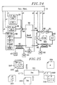
- FIG. 24 illustrates a test bench used to establish, according to the invention, non-linear DUT amplifier characteristic measurements with memory.
- This bench of test whose understanding of the operation is within the reach of the skilled person, in particular comprises an amplitude modulated signal generation block 10 with, for example, two generators SG1 and SG2 of frequencies which can be distinct for apply a multi-carrier signal to the DUT amplifier device to be characterized.
- he further includes a noise measurement block 20 with an NG noise generator white with window and possibly a block 30 for measuring the bit error rate with a MOD generator of signals modulated by a random binary message and a comparator Comp of the original signal and the amplifier return signal.
- FIG. 25 finally illustrates a diagram of the characteristics files set up work by a computer program to simulate the non-linear amplification according to the method of the invention.
- the Pro program thus calls up a file 203 storing results of measurements of static AP characteristics, i.e. of C, ⁇ curves or curves P, Q established at constant amplitude (in a known manner).
- the Pro program still uses a series of files 205, 206, 207 storing dynamic P / I characteristic measurement results as intermodulation rejection curves C1 / C3 or interaction interaction curves C1 / C-1 carriers.
- Each file 205 or 206 or 207 of the series is established for example for a frequency difference df of carriers.
- the program is launched after having entered general data on the amplifier to simulate.
- the Pro program provides a file 204 of the coefficients ⁇ in succession direct transfer functions, in particular Bessel functions. It mainly provides according to the invention files 208, 209 containing the data of the transfer functions E modulation and F correction above.
- Figure 26 shows an example of process step diagram implemented works through such a Pro program.
- the device according to the invention is preferably produced under form of computer program whose functions correspond to blocks shown schematically by way of example in FIGS. 20 to 24.
Abstract
Description
La présente invention concerne le domaine de la simulation de réponse en signal d'amplificateurs non linéaires et a pour objet un système de simulation du signal de réponse d'un amplificateur non-linéaire présentant un effet de mémoire.The present invention relates to the field of response simulation in signal from non-linear amplifiers and relates to a signal simulation system response of a non-linear amplifier with a memory effect.
Une application d'un tel système est la simulation de l'amplification hyperfréquence à haut rendement, notamment en classe AB, B ou C d'amplification et plus particulièrement la simulation de réponse d'amplificateurs de puissance à l'état solide, de type SSPA, et de dispositifs amplificateurs à base de tubes à ondes progressives, de type TOP ou TWT, utilisés dans les liaisons de transmission par faisceau hertzien terrestre ou satellite.An application of such a system is the simulation of amplification high efficiency microwave, in particular in class AB, B or C of amplification and more particularly the simulation of response of power amplifiers in the state solid, SSPA type, and amplifiers based on wave tubes progressive, TOP or TWT type, used in transmission links by terrestrial or satellite radio beam.
A haute fréquence et à haut rendement, de tels dispositifs amplificateurs présentent une caractéristique de réponse non-linéaire.At high frequency and high efficiency, such amplifying devices exhibit a non-linear response characteristic.
La figure 1 illustre un exemple de courbe de réponse entrée-sortie d'amplificateur non-linéaire ANL. La courbe donnant le niveau de signal de sortie g de l'amplificateur ANL en fonction du niveau de signal d'entrée x est typiquement infléchie aux fortes amplitudes A du signal d'entrée x, à cause de phénomènes de saturation. Lorsque l'amplificateur est utilisé dans des conditions telles que le gain n'est pas constant en fonction du niveau de signal d'entrée x, on parle d'amplificateur fonctionnant en régime non-linéaire ou plus simplement d'amplification non-linéaire.Figure 1 illustrates an example of an input-output response curve ANL non-linear amplifier. The curve giving the output signal level g of the amplifier ANL as a function of the input signal level x is typically bent at high amplitudes A of the input signal x, due to phenomena of saturation. When the amplifier is used in conditions such as gain is not constant depending on the input signal level x, we speak of amplifier operating in a non-linear regime or more simply in non-linear amplification.
Parmi les dispositifs non-linéaires, on distingue des dispositifs sans mémoire, quasi-sans-mémoire et à mémoire. Among the non-linear devices, there are devices without memory, almost memoryless and memory.
Les amplificateurs sans mémoire présentent une forte non-linéarité en amplitude et une moindre distorsion de phase. La caractéristique de réponse entrée/sortie d'un amplificateur sans mémoire ANL peut alors se réduire, comme illustré figure 1, à une seule courbe g(x).Amplifiers without memory exhibit strong non-linearity in amplitude and less phase distortion. The response characteristic input / output of an amplifier without ANL memory can then be reduced, as illustrated in figure 1, with a single curve g (x).
On peut modéliser et simuler la réponse en fonction du temps t d'un
amplificateur sans mémoire ANL à un signal d'entrée x sinusoïdal, de fréquence f0,
modulé en amplitude A et en phase , signal ayant donc la forme suivante :
A(t) représente l'enveloppe du signal d'entrée, qui est définie par les limites en amplitude dans lequel le signal sinusoïdal x évolue, l'enveloppe variant en fonction du temps. La figure 3 illustre un chronogramme d'un signal x(t) ayant une enveloppe A constante.A (t) represents the envelope of the input signal, which is defined by the limits in amplitude in which the sinusoidal signal x evolves, the envelope varying according to the time. FIG. 3 illustrates a timing diagram of a signal x (t) having an envelope A constant.
Le signal de sortie g de l'amplificateur sans mémoire est alors de la forme
suivante :
Il est intéressant de donner une enveloppe complexe à ces signaux x et g, en abandonnant toute référence au temps t puisque les amplificateurs sans mémoire ont une réponse instantanée.It is interesting to give a complex envelope to these signals x and g, in abandoning any reference to time t since amplifiers without memory have an instant response.
Le signal d'entrée x de l'équation (1) a une enveloppe complexe X de la forme
suivante :
Toute l'information utile de modulation d'amplitude A(t) et de phase (t) est inscrite dans cette enveloppe complexe X.All the useful amplitude modulation information A (t) and phase (t) is inscribed in this complex envelope X.
Le signal de sortie g de l'équation (2) a de même une enveloppe complexe G
de la forme suivante :
Pour un amplificateur ANL non-linéaire sans mémoire, on démontre que C(A) est la transformée de Chebyshev de la courbe de réponse entrée/sortie g(x).For a non-linear ANL amplifier without memory, we prove that C (A) is the Chebyshev transform of the input / output response curve g (x).
La réponse d'un amplificateur ANL non-linéaire sans mémoire à un signal x modulé peut donc être modélisée et simulée simplement par une seule courbe C(A), dont un exemple est illustré en trait plein sur la figure 6A. Une telle courbe donnant l'amplitude C de sortie en fonction de l'amplitude A d'entrée est appelée courbe de non-linéarité en amplitude et notée en abrégé courbe AM/AM. The response of a non-linear ANL amplifier without memory to a signal x modulated can therefore be modeled and simulated simply by a single curve C (A), an example of which is illustrated in solid lines in FIG. 6A. Such a curve giving the output amplitude C as a function of the input amplitude A is called the amplitude non-linearity and noted abbreviated AM / AM curve.
La figure 2 illustre une caractéristique de réponse d'un amplificateur non-linéaire à mémoire ANLAM, sur laquelle apparaít un phénomène d'hystérésis provoqué par effet de mémorisation. On voit que les courbes de montée m et m' d'hystérésis ne se superposent pas lorsque les amplitudes A et A' respectives du signal d'entrée x sont différentes. La variation du temps de mémorisation liée à la variation d'amplitude empêche les courbes m et m' de se superposer.Figure 2 illustrates a response characteristic of a non-linear amplifier with memory ANLAM, on which a phenomenon of hysteresis appears caused by memory effect. We see that the rise curves m and m ' hysteresis do not overlap when the respective amplitudes A and A 'of the signal input x are different. The variation in the memorization time linked to the variation amplitude prevents the curves m and m 'from overlapping.
Lorsque le temps de mémorisation de l'amplificateur ANLAM est négligeable par rapport à la période de variation d'amplitude A(t), on peut encore considérer que l'amplitude A est stable et on parle d'amplificateur quasi-sans-mémoire.When the memorization time of the ANLAM amplifier is negligible with respect to the amplitude variation period A (t), we can still consider that amplitude A is stable and we speak of a quasi-memoryless amplifier.
La figure 4 représente un chronogramme de signal de sortie y d'un
amplificateur quasi-sans-mémoire auquel est appliqué le signal d'entrée x illustré sur le
chronogramme de la figure 3 dont la formule est rappelée ci-après :
Pour un amplificateur non-linéaire quasi-sans-mémoire auquel on applique le
signal x de l'équation (1), le signal de sortie y prend la forme suivante :
Ainsi, à un instant t donné, l'amplitude C(A) et le déphasage Φ(A) du signal de sortie y dépendent uniquement de l'amplitude A du signal d'entrée x à cet instant t. On peut donc négliger les variations d'amplitude A(t) en fonction du temps, et considérer quasiment que l'amplitude A est constante comme visible figure 3.Thus, at a given time t, the amplitude C (A) and the phase shift Φ (A) of the signal of output y depend only on the amplitude A of the input signal x at this time t. We can therefore neglect the amplitude variations A (t) as a function of time, and consider almost the amplitude A is constant as shown in Figure 3.
Il est également intéressant d'écrire sous forme complexe les enveloppes des
signaux x et y exprimés précédemment, enveloppes X et Y qui prennent les formes
respectives suivantes :
La réponse d'un amplificateur non-linéaire quasi-sans-mémoire peut donc être modélisée et simulée simplement en connaissant deux courbes caractéristiques suivantes :
- une courbe C(A) donnant l'amplitude C du signal de sortie y en fonction de l'amplitude A du signal d'entrée, illustrée par exemple par la courbe AM/AM en trait plein de la figure 6A (courbe de conversion amplitude/amplitude).
- une courbe Φ(A) donnant le déphasage du signal de sortie y par rapport au signal d'entrée x, en fonction de l'amplitude A du signal x, dite courbe de conversion amplitude/phase, en abrégé AM/PM, dont un exemple est illustré en trait plein sur la figure 6B.
- a curve C (A) giving the amplitude C of the output signal y as a function of the amplitude A of the input signal, illustrated for example by the curve AM / AM in solid line in FIG. 6A (amplitude conversion curve /amplitude).
- a curve Φ (A) giving the phase shift of the output signal y with respect to the input signal x, as a function of the amplitude A of the signal x, called the amplitude / phase conversion curve, abbreviated as AM / PM, of which an example is illustrated in solid lines in FIG. 6B.
On démontre que la courbe C(A) est, comme précedement, la norme de la transformée complexe de Chebychev de la caractéristique de réponse y(x), la courbe Φ(A) étant l'argument de la transformée complexe.We show that the curve C (A) is, as before, the norm of the complex Chebychev transform of the response characteristic y (x), the curve Φ (A) being the argument of the complex transform.
L'enveloppe complexe Y du signal de sortie peut également être écrite sous
forme de deux parties, réelles et imaginaires, correspondant à une composante P en
phase et à une composante Q en quadrature de phase, composantes P et Q de formes
suivantes :
La figure 7 illustre un exemple de courbes P(A) et Q(A) équivalentes aux courbes C(A) et Φ(A) des figures 6A et 6B.Figure 7 illustrates an example of curves P (A) and Q (A) equivalent to curves C (A) and Φ (A) of Figures 6A and 6B.
Les modèles connus de simulation de réponse d'amplificateur quasi-sans-mémoire préfèrent généralement utiliser des caractéristiques sous forme de paire de courbes P(A) et Q(A) plutôt que sous forme de paire de courbes C(A) et Φ(A), bien que ces paires de courbes soient strictement équivalentes.The known quasi-memoryless amplifier response simulation models generally prefer to use features as a pair of curves P (A) and Q (A) rather than as a pair of curves C (A) and Φ (A), well that these pairs of curves are strictly equivalent.
Un principe connu de simulation d'amplificateur non-linéaire consiste à précaractériser sur un banc de test l'amplificateur réalisé, la précaractérisation étant effectuée avec un signal de fréquence et d'amplitude déterminées, afin de simuler ensuite la réponse à un signal de fréquence et d'amplitude quelconques.A known principle of non-linear amplifier simulation consists in precharacterize the amplifier produced on a test bench, precharacterization being performed with a signal of determined frequency and amplitude, in order to simulate then the response to a signal of any frequency and amplitude.
Comme schématisé figure 5, un signal monofréquence f0 prenant différentes amplitudes A', A'', A‴ est appliqué à l'amplificateur testé pour obtenir ses caractéristiques, illustrées par exemple en figure 6 ou 7.As shown diagrammatically in FIG. 5, a single frequency signal f 0 taking different amplitudes A ', A'', A ‴ is applied to the amplifier tested to obtain its characteristics, illustrated for example in FIG. 6 or 7.
Cependant, pour des amplificateurs présentant une certaine quantité de mémoire, on constate que les caractéristiques varient de façon importante selon la fréquence f0 -, f0 ou f0 + du signal à amplifier. However, for amplifiers having a certain amount of memory, it can be seen that the characteristics vary significantly depending on the frequency f 0 - , f 0 or f 0 + of the signal to be amplified.
Un système connu de simulation de tels amplificateurs a été exposé par H.B. Poza dans un article intitulé "A Wideband data link computer simulation model", publié dans les actes de conférence "NAECON'75 record", page 71. Il propose d'établir plusieurs paires de courbes AM/AM et AM/PM pour plusieurs fréquences f0 -, f0 ou f0 + de fonctionnement de l'amplificateur. Sur les figures 6A et 6B, on a ainsi représenté un exemple de trois paires de courbes AM/AM et AM/PM, obtenues respectivement à trois fréquences f0 -, f0 et f0 + situées dans la bande utile BU d'un amplificateur de liaison hertzienne.A known system for simulating such amplifiers has been exposed by HB Poza in an article entitled "A Wideband data link computer simulation model", published in the conference proceedings "NAECON'75 record", page 71. He proposes to establish several pairs of AM / AM and AM / PM curves for several frequencies f 0 - , f 0 or f 0 + of amplifier operation. In FIGS. 6A and 6B, an example of three pairs of AM / AM and AM / PM curves has thus been shown, obtained respectively at three frequencies f 0 - , f 0 and f 0 + located in the useful band BU of a radio link amplifier.
Le simulateur de H.B. Poza stocke seulement une paire de courbes AM/AM et AM/PM, par exemple la paire de courbes obtenues à la fréquence f0, et reconstitue les autres paires de courbes (non stockées) correspondant aux autres fréquences f0 -, f0 + ou à des fréquences intermédiaires. Une courbe non stockée est déduite simplement en translatant la courbe stockée d'un vecteur adéquat. Le simulateur calcule les composantes selon l'axe (A) et selon l'axe (C) ou () du vecteur de translation pour rapprocher au mieux la courbe de fréquence f0, représentée en trait plein à la figure 6A ou 6B, de la courbe de fréquence f0 - ou f0 +, représentée en pointillés.HB Poza's simulator stores only a pair of AM / AM and AM / PM curves, for example the pair of curves obtained at the frequency f 0 , and reconstructs the other pairs of curves (not stored) corresponding to the other frequencies f 0 - , f 0 + or at intermediate frequencies. An unstored curve is deduced simply by translating the stored curve of a suitable vector. The simulator calculates the components along the axis (A) and along the axis (C) or () of the translation vector to best approximate the frequency curve f 0 , shown in solid line in FIG. 6A or 6B, of the frequency curve f 0 - or f 0 + , shown in dotted lines.
Un tel système de simulation est trop approximatif pour simuler les distorsions apparaissant sur un amplificateur quasi-sans-mémoire à différentes fréquences.Such a simulation system is too approximate to simulate the distortions appearing on a quasi-memoryless amplifier at different frequencies.
Un autre inconvénient d'un tel système est qu'il ne permet pas de simuler la réponse d'un amplificateur à mémoire.Another disadvantage of such a system is that it does not simulate the response from a memory amplifier.
La figure 9 illustre un autre système connu de simulation, selon le modèle de A.A.M. Saleh, décrit dans un article intitulé "Frequency-independent and frequency-dependent models of TWTA Amplifiers" paru en novembre 1981 dans la revue "IEEE transactions on communication", volume com-29, n° 11, page 1715. Le calcul de la réponse à un signal d'entrée x d'un amplificateur non-linéaire quasi-sans-mémoire est décomposé en deux étapes P(A,f) et Q(A,f) de calcul de deux composantes yp et yq respectives du signal de sortie y. La composante yp est en phase avec le signal d'entrée x, tandis que la composante yq est en quadrature de phase.FIG. 9 illustrates another known system of simulation, according to the model of A.A.M. Saleh, described in an article titled "Frequency-independent and frequency-dependent models of TWTA Amplifiers "published in November 1981 in the review" IEEE transactions on communication ", volume com-29, n ° 11, page 1715. The calculation of the response to an input signal x from a quasi-memoryless non-linear amplifier is decomposed into two stages P (A, f) and Q (A, f) of calculation of two components yp and yq respective of the output signal y. The yp component is in phase with the signal input x, while the component yq is in phase quadrature.
Le système de simulation de Saleh utilise des résultats de caractérisation de l'amplificateur à plusieurs fréquences f, plusieurs paires de courbes P(A) et Q(A) étant établies à plusieurs fréquences f pour calculer des fonctions de transfert P(A,f) et Q(A,f) correspondant à chaque branche de calcul des composantes yp et yq du signal de sortie y. Chacune des fonctions de transfert P(A,f) ou Q(A,f) correspond au calcul d'une réponse non-linéaire sans effet de mémoire, aucun déphasage n'étant introduit dans chacune de ces branches de calcul. Saleh's simulation system uses characterization results from the amplifier at several frequencies f, several pairs of curves P (A) and Q (A) being established at several frequencies f to calculate transfer functions P (A, f) and Q (A, f) corresponding to each branch of calculation of the components yp and yq of the signal output y. Each of the transfer functions P (A, f) or Q (A, f) corresponds to the calculation of a non-linear response without memory effect, no phase shift being introduced in each of these calculation branches.
L'article de A.A.M. Saleh signale que le modèle s'applique à l'amplification de signaux mono-fréquence et, par conjecture, suppose qu'il serait applicable à la simulation de signaux de forme quelconque.The article by A.A.M. Saleh reports that the model applies to the amplification of single frequency signals and, by guesswork, assumes that it would be applicable to the simulation of signals of any shape.
Un autre inconvénient de ce modèle est qu'il ne s'applique pas aux amplificateurs à mémoire, le système ne rendant pas compte des distorsions apparaissant à différentes fréquences lorsque l'amplitude du signal varie rapidement par rapport aux constantes de temps de mémorisation.Another disadvantage of this model is that it does not apply to memory amplifiers, the system not accounting for distortions appearing at different frequencies when the signal amplitude changes rapidly compared to the storage time constants.
Pour les amplificateurs non-linéaires à mémoire ANLAM, les effets de mémorisation sont plus importants, les temps de mémorisation n'étant pas négligeables par rapport aux temps de variation de l'amplitude A(t). Dans de tels cas, des méthodes plus complexes telles que la résolution d'équations différentielles non-linéaires ou le développement des caractéristiques en suites de fonctions sont nécessaires pour simuler la réponse de l'amplificateur à mémoire ANLAM.For non-linear amplifiers with ANLAM memory, the effects of memorization are more important, memorization times are not negligible with respect to the times of variation of the amplitude A (t). In such cases, methods more complex such as solving nonlinear differential equations or the development of features in function suites are necessary for simulate the response of the ANLAM memory amplifier.
Un modèle connu plus perfectionné est proposé par M.T. Abuelma'atti dans un article intitulé "Frequency-dependent nonlinear quadrature model for TWT amplifiers", paru en août 1984, dans la revue IEEE transaction on communication, volume com-32, N° 8, page 982. La modélisation utilise un développement des courbes caractéristiques d'un amplificateur non-linéaire en suite de fonctions de Bessel, ce qui permet de simuler la réponse d'amplificateurs à mémoire.A more sophisticated known model is proposed by M.T. Abuelma'atti in a article titled "Frequency-dependent nonlinear quadrature model for TWT amplifiers ", published in August 1984, in the journal IEEE transaction on communication, volume com-32, N ° 8, page 982. The modeling uses a development of characteristic curves of a non-linear amplifier following functions of Bessel, which simulates the response of memory amplifiers.
La figure 10 illustre le système de simulation décrit par M.T. Abuelma'atti qui comporte comme précédemment deux branches de calcul des composantes en phase yp et en quadrature yq du signal de sortie y, chaque branche calculant la contribution d'une suite de N fonctions de Bessel J1 dépendant de l'amplitude A du signal d'entrée x, en pondérant chaque fonction J1 d'un coefficient α et d'un facteur G(f) de correction en fréquence. Les coefficients αn et les facteurs Gn(f) sont calculés après avoir établi plusieurs paires de courbes P(A) et Q(A) caractéristiques de l'amplificateur non-linéaire, les courbes étant établies à plusieurs fréquences f de test de l'amplificateur.FIG. 10 illustrates the simulation system described by MT Abuelma'atti which as before comprises two branches for calculating the components in phase yp and in quadrature yq of the output signal y, each branch calculating the contribution of a series of N functions of Bessel J1 depending on the amplitude A of the input signal x, by weighting each function J1 by a coefficient α and a factor G (f) of frequency correction. The coefficients α n and the factors G n (f) are calculated after having established several pairs of curves P (A) and Q (A) characteristic of the non-linear amplifier, the curves being established at several test frequencies f the amplifier.
Avec la figure 8, on peut voir qu'une double sommation pondérée de N fonctions de Bessel du premier type d'ordre 1, notées J1(nπA/D) permet d'interpoler très précisément une paire de courbes P(A) et Q(A), comme les deux courbes de la figure 7, en ajustant les coefficients αnp et αnq de pondération de ces fonctions J1.With Figure 8, we can see that a double weighted summation of N Bessel functions of the first type of order 1, denoted J1 (nπA / D) allows to very precisely interpolate a pair of curves P (A) and Q (A), like the two curves in Figure 7, by adjusting the coefficients α np and α nq of weighting of these functions J1.
On peut noter que les fonctions de Bessel sont les transformées de Chebychev de fonctions sinusoïdales et que le développement en suite de fonctions de Bessel des courbes P(A) et Q(A) correspond à un développement de Fourier en suite de fonctions sinusoïdales des courbes y(x) de non-linéarité de l'amplificateur, ce qui convient élégamment à l'allure sinusoïdale des courbes d'hystérésis y(x), tel qu'illustrées figure 2.We can note that the Bessel functions are the Chebychev transforms of sinusoidal functions and that the development following Bessel functions of curves P (A) and Q (A) corresponds to a Fourier expansion following sinusoidal functions of the amplifier's non-linearity curves y (x), which elegantly suited to the sinusoidal shape of the hysteresis curves y (x), such as illustrated in figure 2.
Théoriquement, un tel système devrait permettre la simulation de l'amplification de signaux multi-porteuses, c'est-à-dire de signaux comportant plusieurs composantes sinusoïdales de fréquences distinctes.Theoretically, such a system should allow the simulation of amplification of multi-carrier signals, i.e. signals comprising several sinusoidal components of distinct frequencies.
Toutefois, l'amplification non-linéaire d'un signal d'entrée multi-porteuses est compliquée par l'apparition de distorsions appelées phénomènes d'intermodulation. Lorsqu'un amplificateur non-linéaire reçoit en entrée plusieurs fréquences porteuses, on obtient en sortie, en plus des porteuses amplifiées, des harmoniques non désirées appelées produits d'intermodulation, chaque harmonique ayant une fréquence distincte des fréquences des porteuses.However, the non-linear amplification of a multi-carrier input signal is complicated by the appearance of distortions called intermodulation phenomena. When a non-linear amplifier receives several carrier frequencies as input, undesired harmonics are obtained at the output, in addition to the amplified carriers called intermodulation products, each harmonic having a separate frequency carrier frequencies.
Les figures 11-14 illustrent l'apparition du phénomène d'intermodulation lors de l'amplification non-linéaire d'un signal à deux porteuses.Figures 11-14 illustrate the appearance of the intermodulation phenomenon during non-linear amplification of a two-carrier signal.
La figure 11 représente un diagramme fréquentiel de signal d'entrée x biporteuses, sur lequel on voit par exemple, deux composantes porteuses de fréquences respectives f-1 et f1 ayant une égale amplitude A d'entrée. Les deux fréquences porteuses f-1 et f1, situées dans la bande utile BU de fréquence de l'amplificateur, sont séparées par un écart fréquentiel df.FIG. 11 represents a frequency diagram of input signal x two-carrier, on which we see for example, two carrier components of respective frequencies f -1 and f 1 having an equal amplitude A input. The two carrier frequencies f -1 and f 1 , located in the useful band BU of the amplifier frequency, are separated by a frequency difference df.
La figure 14 représente un diagramme fréquentiel de signal de sortie y qui correspond à l'amplification ANLAM avec effet de mémoire du signal d'entrée x biporteuse de la figure 11. On voit que le signal de sortie y comporte une série d'harmoniques de diverses fréquences f et d'amplitudes C différentes.FIG. 14 represents a frequency diagram of output signal y which corresponds to ANLAM amplification with memory effect of the input signal x two-carrier in Figure 11. We see that the output signal has a series of harmonics of various frequencies f and of different amplitudes C.
La fréquence de chacune des composantes d'intermodulation est une combinaison entière des fréquences porteuses en entrée.The frequency of each of the intermodulation components is a integer combination of input carrier frequencies.
Le détail des harmoniques de sortie comprises dans la bande utile BU, illustrées figure 14, est le suivant:
- les porteuses, de fréquence f-1 et f1, et d'amplitude de sortie respectives C-1 et C1.
- les composantes d'intermodulation d'ordre 3, de fréquences f-3, f3, et d'amplitudes de sortie respectives C-3, C3.
- the carriers, of frequency f -1 and f 1 , and of respective output amplitude C -1 and C 1 .
- the intermodulation components of order 3, of frequencies f -3 , f 3 , and of respective output amplitudes C -3 , C 3 .
La figure 15 reproduit des résultats fournis par le modèle d'Abuelma'atti qui a permis une estimation des amplitudes C-1, C1, et C-3, C3 de sortie des composantes porteuses et des composantes d'intermodulation d'ordre 3. Figure 15 reproduces results provided by the Abuelma'atti model which allowed an estimation of the amplitudes C -1 , C 1 , and C -3 , C 3 of output of the carrier components and the order intermodulation components 3.
Toutefois, l'estimation de l'amplitude des composantes d'intermodulation par le modèle d'Abuelma'atti correspond mal à la réalité des mesures de distorsions d'intermodulation lors de l'amplification de signaux multi-porteuses hyperfréquences par un amplificateur à mémoire en fonctionnement non-linéaire à haut rendement.However, the estimation of the amplitude of the intermodulation components by the Abuelma'atti's model does not correspond well to the reality of distortion measurements intermodulation when amplifying multi-carrier microwave signals by a memory amplifier in non-linear operation with high efficiency.
Il se produit en effet un phénomène général, appelé mémoire d'enveloppe lorsqu'on amplifie un signal multi-porteuses. Pour ce type de signal, l'enveloppe, définie par les limites positive et négative en amplitude du signal, n'est pas constante.There is indeed a general phenomenon, called envelope memory when amplifying a multi-carrier signal. For this type of signal, the envelope, defined by the positive and negative limits in amplitude of the signal, is not constant.
Dans ce cas, on ne peut plus considérer que l'enveloppe est constante comme dans les modèles quasi-sans mémoire. En fait, les constantes de temps de mémorisation ne sont plus négligeables vis-à-vis du temps de variation de l'enveloppe.In this case, we can no longer consider that the envelope is constant as in almost memoryless models. In fact, the time constants of storage are no longer negligible with respect to the time of variation of the envelope.
La figure 12 qui illustre l'évolution temporelle du signal d'entrée x biporteuses de la figure 11, montre par exemple que l'enveloppe X(t) et -X(t) du signal biporteuse varie très rapidement et dans des proportions importantes, alors que l'amplitude A de chaque porteuse f1 et f-1 porteuse est supposée constante.FIG. 12 which illustrates the temporal evolution of the input signal x two-carrier of FIG. 11, shows for example that the envelope X (t) and -X (t) of the two-carrier signal varies very quickly and in significant proportions, whereas the amplitude A of each carrier f 1 and f -1 carrier is assumed to be constant.
La figure 13 qui illustre l'évolution temporelle du signal de sortie y correspondant au signal d'entrée x biporteuse précédent, montre ainsi que l'enveloppe Y(t) et -Y(t) du signal de sortie y, apparaít alors très déformée par les distorsions d'intermodulation. On désigne sous le nom d'effet de mémoire d'enveloppe de telles déformations d'amplitude du signal par un amplificateur non-linéaire à mémoire.FIG. 13 which illustrates the temporal evolution of the output signal y corresponding to the previous input signal x two-carrier, thus shows that the envelope Y (t) and -Y (t) of the output signal y, then appears very distorted by the distortions intermodulation. These are referred to as the envelope memory effect. amplitude distortions of the signal by a non-linear amplifier with memory.
Les modèles connus ne rendent pas compte, en particulier, de deux effets illustrés aux figures 16 et 17.Known models do not account, in particular, for two effects illustrated in Figures 16 and 17.
Le premier effet observé est que le ratio C1/C3 illustré figure 16, comparant l'amplitude C1 de porteuses par rapport à l'amplitude C3 des composantes d'intermodulation, varie considérablement selon l'écart fréquentiel df des porteuses et selon la valeur précise de l'amplitude A des porteuses du signal d'entrée.The first effect observed is that the C1 / C3 ratio illustrated in Figure 16, comparing the amplitude C1 of carriers with respect to the amplitude C3 of the components intermodulation, varies considerably according to the frequency difference df of the carriers and according to the precise value of the amplitude A of the carriers of the input signal.
Si on appliquait le modèle d'Abuelma'atti, le ratio C1/C3 ne dépendrait pas de l'écart fréquentiel et varierait continûment selon l'amplitude A d'entréeIf we applied Abuelma'atti's model, the C1 / C3 ratio would not depend on the frequency deviation and would vary continuously depending on the amplitude A of input
Le second effet observé est que la présence d'une seconde porteuse influence l'amplitude de sortie de la première porteuse.The second effect observed is that the presence of a second carrier influences the output amplitude of the first carrier.
La figure 17 montre par exemple des pics d'affaiblissement ou de résonnance d'amplitude C1 ou C-1 de sortie de chacune des porteuses de fréquence f1 ou f-1, selon l'écart fréquentiel df des deux porteuses (df valant f1-f-1).FIG. 17 shows for example peaks of weakening or resonance of amplitude C1 or C-1 of output of each of the carriers of frequency f 1 or f -1 , according to the frequency difference df of the two carriers (df being equal to f 1 -f -1 ).
Un inconvénient des modèles connus est de nepas rendre compte de ces effets.A disadvantage of the known models is that they do not account for these effects.
De façon générale, l'inconvénient des modèles connus est qu'ils ne simulent pas d'effet de mémoire d'enveloppe. Generally, the disadvantage of known models is that they do not simulate envelope memory effect.
L'objet de l'invention est de réaliser un système de simulation de réponse en signal d'un amplificateur non-linéaire présentant un effet de mémoire sans les inconvénients précités.The object of the invention is to provide a response simulation system by signal from a non-linear amplifier having a memory effect without them aforementioned drawbacks.
Un but premier de l'invention est d'obtenir des simulations précises des effets de mémoire d'enveloppe sur des amplificateurs non-linéaires.A primary object of the invention is to obtain precise simulations of the effects of envelope memory on non-linear amplifiers.
Un but particulier de l'invention est d'obtenir des simulations précises de l'amplification de signaux multi-porteuses par un amplificateur non-linéaire à mémoire.A particular object of the invention is to obtain precise simulations of amplification of multi-carrier signals by a non-linear memory amplifier.
Un autre but de l'invention est de réaliser un système simple de simulation de réponse d'amplificateurs non-linéaires à mémoire.Another object of the invention is to provide a simple system for simulating response from non-linear memory amplifiers.
Succintement, pour atteindre ces buts, l'invention prévoit une mesure dynamique des caractéristiques de l'amplificateur dans les conditions où apparaissent les distorsions, c'est-à-dire avec un signal modulé en amplitude, ce qui permet de faire varier l'enveloppe du signal.Succinctly, to achieve these goals, the invention provides a measure dynamic characteristics of the amplifier under the conditions where distortions, that is to say with an amplitude modulated signal, which makes it possible to vary the signal envelope.
Ainsi, il est prévu, selon l'invention, de mesurer des caractéristiques de distorsions de modulation d'amplitude, chaque mesure étant effectuée en modulant l'amplitude d'entrée. Ces mesures de caractéristiques de distorsions de modulation permettent de calculer des fonctions de transfert de modulation reproduisant en sortie les amplitudes des distorsions selon les amplitudes de modulation en entrée. Enfin, il est prévu que les amplitudes de distorsions reproduites par les fonctions de transfert de modulation corrigent la sortie de fonctions de transfert directes d'un modèle connu. Pour rappel, les modèles connus ont été obtenus en mesurant des caractéristiques de conversion amplitude/amplitude et de conversion amplitude/déphasage de l'amplificateur, chaque mesure étant effectuée à amplitude constante en entrée, puis en développant les caractéristiques en suite de fonction de transfert directes.Thus, according to the invention, provision is made to measure characteristics of amplitude modulation distortions, each measurement being made by modulating the input amplitude. These measurements of modulation distortion characteristics allow to calculate modulation transfer functions reproducing at output the amplitudes of the distortions according to the amplitudes of modulation at input. Finally, it it is expected that the amplitudes of distortions reproduced by the transfer functions modulation correct the output of direct transfer functions from a known model. As a reminder, the known models were obtained by measuring characteristics of amplitude / amplitude conversion and amplitude / phase shift conversion of the amplifier, each measurement being carried out at constant amplitude at the input, then at developing the characteristics as a result of direct transfer function.
Les mesures de caractéristiques de distorsions de modulation sont effectués plus précisément avec des signaux multi-porteuses, c'est-à-dire en apliquant des signaux comportant plusieurs composantes fréquentielles (porteuses) en entrée de l'amplificateur non-linéaire, les signaux amplifiés en sortie présentant une multitude de composantes fréquentielles (porteuses amplifiées + produits d'intermodulation).Modulation distortion characteristic measurements are performed more precisely with multi-carrier signals, that is to say by applying signals comprising several frequency components (carriers) at input of the non-linear amplifier, the amplified signals at the output presenting a multitude of frequency components (amplified carriers + intermodulation products).
L'invention est réalisée en mettant en oeuvre un procédé de simulation de réponse en signal d'un amplificateur non-linéaire présentant un effet de mémoire, le procédé comportant des étapes consistant à :
- mesurer des caractéristiques de conversion amplitude/amplitude et de conversion amplitude/déphasage de l'amplificateur, chaque mesure étant effectuée à amplitude constante en entrée,
- développer les caractéristiques en suite de fonctions de transfert directes établissant l'amplitude et le déphasage de sortie selon l'amplitude d'entrée,
- mesurer des caractéristiques de distorsions de modulation de l'amplificateur en appliquant un signal comportant au moins deux composantes fréquentielles en entrée, les caractéristiques de distorsions de modulation étant mesurées pour plusieurs écarts fréquentiels et/ou plusieurs amplitudes des composantes fréquentielles, chaque mesure donnant l'amplitude de composantes fréquentielles de sortie en fonction de l'écart fréquentiel et de l'amplitude des composantes fréquentielles d'entrée, et
- calculer, d'après les mesures de caractéristiques de distorsions de modulation, une fonction de transfert de modulation corrigeant l'amplitude de composantes fréquentielles de sortie des fonctions de transfert directes lorsque l'amplitude d'entrée est modulée, selon les écarts fréquentiels et les amplitudes des composantes fréquentielles d'entrée, afin de simuler l'effet de mémoire d'enveloppe.
- measure amplitude / amplitude conversion and amplitude / phase shift conversion characteristics of the amplifier, each measurement being carried out at constant amplitude at input,
- develop the characteristics following direct transfer functions establishing the output amplitude and phase shift according to the input amplitude,
- measuring characteristics of modulation distortions of the amplifier by applying a signal comprising at least two frequency components at input, the characteristics of modulation distortions being measured for several frequency deviations and / or several amplitudes of the frequency components, each measurement giving the amplitude of the output frequency components as a function of the frequency deviation and of the amplitude of the input frequency components, and
- calculating, from the measurements of modulation distortion characteristics, a modulation transfer function correcting the amplitude of the output frequency components of the direct transfer functions when the input amplitude is modulated, according to the frequency deviations and the amplitudes of the input frequency components, in order to simulate the effect of envelope memory.
De préférence, le procédé selon l'invention comporte des étapes intercalaires consistant à :
- mesurer les caractéristiques à différentes fréquences, et
- calculer des correcteurs en fréquence pour les fonctions de transfert directes.
- measure characteristics at different frequencies, and
- calculate frequency correctors for direct transfer functions.
Une première réalisation du procédé selon l'invention prévoit de :
- mesurer des caractéristiques de réjection de composantes d'intermodulation apparaissant en sortie de l'amplificateur non-linéaire à des fréquences différentes des fréquences des composantes d'entrée, chaque mesure donnant l'amplitude de composantes d'intermodulation en fonction de l'écart fréquentiel et de l'amplitude des composantes fréquentielles d'entrée, et de
- calculer, d'après les mesures de caractéristiques de réjection de composantes d'intermodulation, une fonction de transfert de modulation établissant, selon les écarts fréquentiels et les amplitudes des composantes fréquentielles d'entrée, un signal modulateur modulant l'amplitude de composantes de sortie des fonctions de transfert directes, notamment l'amplitude des composantes fréquentielles d'intermodulation d'ordre trois.
- measuring the rejection characteristics of intermodulation components appearing at the output of the non-linear amplifier at frequencies different from the frequencies of the input components, each measurement giving the amplitude of intermodulation components as a function of the frequency difference and the amplitude of the input frequency components, and
- calculating, from the measurements of intermodulation component rejection characteristics, a modulation transfer function establishing, according to the frequency deviations and the amplitudes of the input frequency components, a modulating signal modulating the amplitude of output components direct transfer functions, in particular the amplitude of the order three intermodulation frequency components.
De préférence si l'amplificateur est dissymétrique en fréquence, il est prévu de:
- mesurer deux facteurs de réjection de composantes d'intermodulation pour chaque écart fréquentiel et chaque amplitude des composantes fréquentielles d'entrée,
- calculer une fonction de transfert de modulation dissymétrique ayant une réponse à un écart fréquentiel négatif distincte de la réponse à un écart fréquentiel positif.
- measure two rejection factors of intermodulation components for each frequency deviation and each amplitude of the input frequency components,
- calculating an asymmetric modulation transfer function having a response to a negative frequency deviation distinct from the response to a positive frequency deviation.
Une deuxième réalisation du procédé selon l'invention prévoit de :
- mesurer des caractéristiques d'interaction de composantes fréquentielles en appliquant un signal comportant au moins deux composantes fréquentielles en entrée de l'amplificateur non-linéaire, chaque mesure donnant l'amplitude de sortie desdites composantes fréquentielles en fonction de l'écart fréquentiel et de l'amplitude d'entrée desdites composantes fréquentielles, et de
- calculer, d'après les mesures de caractéristiques d'interaction de composantes fréquentielles, une fonction de transfert de correction établissant, selon les écarts fréquentiels et les amplitudes des composantes fréquentielles d'entrée, un signal de correction ajustant l'amplitude ou l'amplitude modulée de composantes fréquentielles issues des fonctions de transfert directes.
- measuring interaction characteristics of frequency components by applying a signal comprising at least two frequency components at the input of the non-linear amplifier, each measurement giving the output amplitude of said frequency components as a function of the frequency difference and of l input amplitude of said frequency components, and
- calculating, from the measurements of interaction characteristic of the frequency components, a correction transfer function establishing, according to the frequency deviations and the amplitudes of the input frequency components, a correction signal adjusting the amplitude or the amplitude modulated with frequency components from direct transfer functions.
De préférence, comme l'amplificateur a une variation de gain de porteuses en fonction de la fréquence d'enveloppe, il est prévu de mesurer des caractéristiques de gain en amplitude pour une porteuse en présence d'une autre porteuse en fonction de l'écart féquentiel des porteuses.Preferably, as the amplifier has a variation in carrier gain in depending on the envelope frequency, it is planned to measure characteristics of amplitude gain for a carrier in the presence of another carrier as a function of the carrier differential.
Une troisième réalisation du procédé selon l'invention prévoit de :
- mesurer des caractéristiques de bruit de modulation en sortie, chaque mesure étant effectuée avec des amplitudes déterminées de modulation en entrée. En particulier, il est prévu de:
- mesurer des caractéristiques de report (NPR) de bruit dans une fenêtre (BH) de fréquence, chaque mesure étant effectuée avec un bruit blanc (DSP) à fenêtre (BH) en entrée.
- measuring noise modulation characteristics at output, each measurement being carried out with determined amplitudes of modulation at input. In particular, it is planned to:
- measure noise transfer characteristics (NPR) in a frequency window (BH), each measurement being carried out with a white noise (DSP) at the input window (BH).
L'invention est réalisée en outre avec un dispositif de simulation de réponse en signal d'un amplificateur non-linéaire présentant un effet de mémoire, le dispositif comportant :
- un module de calcul de la réponse d'un amplificateur non-linéaire à un signal
monoporteuse, le module comportant :
- au moins un filtre direct ayant une fonction de transfert établie à partir de caractéristiques de conversion amplitude/amplitude et de conversion amplitude/déphasage, mesurées réellement sur l'amplificateur, chaque fonction de transfert directe étant établie avec un signal monoporteuse prenant différentes amplitudes,
- des moyens de génération d'harmoniques en réponse à un signal multi-porteuses, et
- au moins un filtre de modulation de la réponse du module de calcul, le filtre de modulation ayant une fonction de transfert établie à partir de caractéristiques de distorsions de modulation d'amplitude mesurées réellement sur l'amplificateur, chaque fonction de transfert de modulation étant établie avec des signaux multi-porteuses. De préférence, le module du dispositif selon l'invention comporte en outre :
- au moins un correcteur en fréquence pondérant la fonction de transfert d'un filtre direct, chaque correcteur ayant une fonction de correction établie à partir de caractéristiques de conversion mesurées sur l'amplificateur à différentes fréquences de signal monoporteuse.
- a module for calculating the response of a non-linear amplifier to a single-carrier signal, the module comprising:
- at least one direct filter having a transfer function established on the basis of amplitude / amplitude conversion and amplitude / phase shift conversion characteristics, actually measured on the amplifier, each direct transfer function being established with a single-carrier signal taking different amplitudes,
- means for generating harmonics in response to a multi-carrier signal, and
- at least one modulation filter of the response of the calculation module, the modulation filter having a transfer function established on the basis of amplitude modulation distortion characteristics actually measured on the amplifier, each modulation transfer function being established with multi-carrier signals. Preferably, the module of the device according to the invention further comprises:
- at least one frequency corrector weighting the transfer function of a direct filter, each corrector having a correction function established on the basis of conversion characteristics measured on the amplifier at different frequencies of single-carrier signal.
Les moyens de génération d'harmoniques du dispositif comportent de préférence selon l'invention un module de décomposition de Fourier d'un signal en composantes fréquentielles et/ou un module combinatoire calculant les combinaisons de fréquence de composantes d'intermodulation et/ou un module normatif calculant une valeur efficace d'amplitude de signal.The means for generating harmonics of the device include preferably according to the invention a Fourier decomposition module of a signal into frequency components and / or a combinatorial module calculating the combinations frequency of intermodulation components and / or a normative module calculating an effective signal amplitude value.
Un premier mode de réalisation de dispositif selon l'invention prévoit que le filtre de modulation a une fonction de transfert établie à partir de caractéristiques de réjection de composantes d'intermodulation, de sorte que des composantes d'intermodulation d'amplitude calculée par le filtre de modulation sont ajoutées à la réponse du module de calcul lorsque l'amplification d'un signal multi-porteuses est simulée par le dispositif.A first embodiment of the device according to the invention provides that the modulation filter has a transfer function established from characteristics of rejection of intermodulation components, so that components amplitude intermodulation calculated by the modulation filter are added to the response of the calculation module when the amplification of a multi-carrier signal is simulated by the device.
Un deuxième mode de réalisation de dispositif selon l'invention prévoit en outre un filtre de correction de la réponse du module de calcul, le filtre ayant une fonction de transfert établie à partir de caractéristiques d'interaction de porteuses, de sorte que l'amplitude d'une porteuse fournie par le module de calcul est corrigée par le filtre de correction lorsque l'amplification d'un signal multi-porteuses est simulée par le dispositif.A second embodiment of the device according to the invention provides in in addition to a filter for correcting the response of the calculation module, the filter having a transfer function established from interaction characteristics of carriers, so that the amplitude of a carrier provided by the calculation module is corrected by the correction filter when the amplification of a multi-carrier signal is simulated by the device.
L'invention s'applique de façon avantageuse à la simulation de réponse en signal d'un amplificateur hyperfréquence fonctionnant à haut rendement.The invention advantageously applies to the simulation of response in signal from a high efficiency microwave amplifier.
D'autres caractéristiques, buts et avantages de la présente invention apparaítront à la lecture de la description détaillée qui va suivre, et des dessins annexés, donnés à titre d'exemples non limitatifs. Other features, objects and advantages of the present invention will appear on reading the detailed description which follows, and of the drawings attached, given by way of nonlimiting examples.
Sur les dessins annexés :
- les figures 1 et 2, précédemment décrites, illustrent des courbes de réponse d'amplificateurs non-linéaires ;
- les figures 3 et 4, précédemment décrites, illustrent des diagrammes temporels de réponse en signal d'amplificateur non-linéaire sans mémoire ou quasi-sans-mémoire ;
- la figure 5, précédemment décrite, schématise un diagramme fréquentiel de mesures de caractéristiques selon un principe connu ;
- les figures 6A et 6B, précédemment décrites, illustrent des caractéristiques d'amplificateur non-linéaire sous forme de courbes de conversion amplitude/amplitude et de courbes de conversion amplitude/déphasage, obtenues selon un procédé connu ;
- la figure 7, précédemment décrite, illustre des caractéristiques d'amplificateur non-linéaire, sous forme de courbes de non-linéarité en phase et en quadrature, obtenues selon un procédé équivalent connu;
- la figure 8, précédemment décrite, illustre une suite de fonction de Bessel de décomposition des caractéristiques mises en oeuvre dans un procédé de simulation connu ;
- les figures 9 et 10, précédemment décrites, représentent deux dispositifs de simulation connus ;
- les figures 11 et 14, précédemment décrites, illustrent des diagrammes fréquentiels d'amplitude de signaux multi-porteuses, respectivement en entrée et en sortie d'un amplificateur non-linéaire à mémoire ;
- les figures 12 et 13, précédemment décrites, illustrent des diagrammes temporels d'amplitude de signaux multi-porteuses, respectivement en entrée et en sortie d'un amplificateur non-linéaire à mémoire ;
- la figure 15, précédemment décrite, reproduit des résultats de simulation d'amplitudes de composantes fréquentielles de sortie d'un amplificateur non-linéaire selon l'amplitude des porteuses d'un signal d'entrée bi-porteuses, simulation effectuée selon un modèle connu ;
- la figure 16 illustre des mesures de réjection de composante d'intermodulation en sortie par rapport aux composantes porteuses en entrée d'un amplificateur non-linéaire à mémoire exprimé sous forme de ratio C1/C3 d'amplitude de sortie de porteuse/amplitude de composante d'intermodulation, en fonction de l'amplitude A en entrée des porteuses, pour divers écarts fréquentiels df des porteuses, mesures mises en oeuvre selon l'invention ;
- la figure 17 illustre des mesures d'interaction de porteuses en sortie d'un amplificateur non-linéaire à mémoire, sous forme d'amplitude de sortie y d'une porteuse en fonction de l'écart fréquentiel des porteuses, mesures mises en oeuvre selon l'invention ;
- la figure 18 représente un diagramme fréquentiel de mesures de caractéristiques mis en oeuvre selon l'invention ;
- Les figures 19A et 19B représentent des exemples de densité spectrale de puissance (DSP) du signal utilisé en entrée de l'amplificateur pour la mesure du NPR ;
- la figure 20 représente une réalisation de dispositif de simulation d'amplification non-linéaire à mémoire comportant des moyens de génération d'harmoniques selon l'invention ;
- la figure 21 représente un premier mode de réalisation de dispositif de simulation d'amplification non-linéaire à mémoire selon l'invention ;
- la figure 22 représente une variante du premier mode de réalisation de dispositif de simulation d'amplification non-linéaire à mémoire selon l'invention;
- la figure 23 représente un deuxième mode de réalisation de dispositif de simulation d'amplification non-linéaire à mémoire selon l'invention ;
- la figure 24 représente un banc de mesure de caractéristiques de distorsions d'intermodulation utilisé par le procédé ou le dispositif selon l'invention ;
- la figure 25 représente un diagramme de fichiers de caractéristiques mis en oeuvre par un processus de simulation de réponse d'un amplificateur non-linéaire selon l'invention ; et,
- la figure 26 représente un schéma d'étapes de processus de simulation de réponse d'un amplificateur non-linéaire selon l'invention.
- Figures 1 and 2, previously described, illustrate response curves of non-linear amplifiers;
- FIGS. 3 and 4, previously described, illustrate time diagrams of response in non-linear amplifier signal without memory or quasi-memoryless;
- FIG. 5, previously described, diagrams a frequency diagram of characteristic measurements according to a known principle;
- FIGS. 6A and 6B, previously described, illustrate the characteristics of a non-linear amplifier in the form of amplitude / amplitude conversion curves and amplitude / phase shift conversion curves, obtained according to a known method;
- FIG. 7, previously described, illustrates the characteristics of a non-linear amplifier, in the form of non-linearity curves in phase and in quadrature, obtained according to a known equivalent method;
- FIG. 8, previously described, illustrates a sequence of Bessel functions for decomposing the characteristics implemented in a known simulation method;
- Figures 9 and 10, previously described, show two known simulation devices;
- FIGS. 11 and 14, previously described, illustrate frequency diagrams of amplitude of multi-carrier signals, respectively at the input and at the output of a non-linear amplifier with memory;
- FIGS. 12 and 13, previously described, illustrate time diagrams of amplitude of multi-carrier signals, respectively at the input and at the output of a non-linear amplifier with memory;
- FIG. 15, previously described, reproduces simulation results of amplitudes of frequency component outputs of a non-linear amplifier according to the amplitude of the carriers of a bi-carrier input signal, simulation carried out according to a known model ;
- FIG. 16 illustrates measurements of rejection of intermodulation component at output with respect to the carrier components at input of a non-linear amplifier with memory expressed in the form of ratio C1 / C3 of amplitude of carrier output / amplitude of component intermodulation, as a function of the amplitude A at the input of the carriers, for various frequency differences df of the carriers, measures implemented according to the invention;
- FIG. 17 illustrates measurements of carrier interaction at the output of a non-linear amplifier with memory, in the form of output amplitude y of a carrier as a function of the frequency difference of the carriers, measurements implemented according to the invention;
- FIG. 18 represents a frequency diagram of characteristic measurements implemented according to the invention;
- FIGS. 19A and 19B show examples of power spectral density (DSP) of the signal used at the input of the amplifier for measuring the NPR;
- FIG. 20 represents an embodiment of a non-linear amplification simulation device with memory comprising means for generating harmonics according to the invention;
- FIG. 21 represents a first embodiment of a non-linear amplification simulation device with memory according to the invention;
- FIG. 22 shows a variant of the first embodiment of a memory non-linear amplification simulation device according to the invention;
- FIG. 23 represents a second embodiment of a non-linear amplification simulation device with memory according to the invention;
- FIG. 24 represents a bench for measuring characteristics of intermodulation distortions used by the method or the device according to the invention;
- FIG. 25 represents a diagram of characteristics files implemented by a response simulation process of a non-linear amplifier according to the invention; and,
- FIG. 26 represents a diagram of process steps for simulating the response of a non-linear amplifier according to the invention.
Les procédé et dispositif de simulation selon l'invention sont développés à partir des modélisations connues.The simulation methods and device according to the invention are developed at from known models.
L'invention se propose de simuler l'amplification de signaux de forme quelconque et notamment de signaux comportant plusieurs composantes fréquentielles.The invention proposes to simulate the amplification of shape signals any and especially of signals comprising several components frequency.
Selon une première caractéristique de dispositif selon l'invention, le dispositif de simulation comporte des moyens de génération d'harmoniques en réponse à un signal multi-porteuses.According to a first characteristic of the device according to the invention, the device simulation includes means for generating harmonics in response to a multi-carrier signal.
Ainsi les diverses structures, illustrées aux figures 21 à 23, de dispositif selon l'invention, comportent systématiquement un bloc 11 ou 21 ou 31 de calcul de signal de sortie y selon un modèle connu et un bloc parallèle 12 ou 22, 23 ou 32 de génération d'harmoniques qui calcule les fréquences des composantes d'intermodulation avant le calcul de leur amplitude précise pour corriger le signal de sortie y. Les blocs de calcul de signal de sortie 11, 21 et 31 sont prévus pour mettre en oeuvre un modèle de simulation connu, par exemple et respectivement le modèle non-linéaire sans mémoire MNLSM de H.B. Poza, le modèle non-linéaire sans mémoire MNLSM quadratique de A.A.M. Saleh et le modèle à mémoire MM de M.T. Abuelma'atti. D'autres modèles peuvent être mis en oeuvre, et la description de la mise en oeuvre de l'invention sera développée essentiellement à partir du modèle perfectionné de M.T. Abuelma'atti.Thus the various structures, illustrated in FIGS. 21 to 23, of device according to the invention, systematically include a block 11 or 21 or 31 for signal calculation output y according to a known model and a parallel block 12 or 22, 23 or 32 of generation of harmonics which calculates the frequencies of the components intermodulation before calculating their precise amplitude to correct the signal exit there. The output signal calculation blocks 11, 21 and 31 are provided for putting implement a known simulation model, for example and respectively the model non-linear without memory MNLSM by H.B. Poza, the non-linear model without Quadratic MNLSM memory of A.A.M. Saleh and the MM memory model of M.T. Abuelma'atti. Other models can be implemented, and the description of the implementation of the invention will be developed mainly from the model perfected by M.T. Abuelma'atti.
On notera que la structure en parallèle des blocs de calcul de sortie MNLSM ou MM et des blocs Harm de génération d'harmoniques est indicative, la structure des blocs pouvant être en série, et la réalisation effective des blocs de calculs étant de préférence effectuée par des programmes d'ordinateur, les blocs schématisant dans ce cas les fonctions de sous-programmes de calcul.Note that the parallel structure of the MNLSM output calculation blocks or MM and Harm blocks for generating harmonics is indicative, the structure of blocks being able to be in series, and the effective realization of the blocks of calculations being of preferably done by computer programs, the blocks schematically in this case the functions of calculation subroutines.
La figure 23 décrit le détail d'une réalisation alternative de moyens Harm de génération d'harmoniques et de moyens MM de calcul des composantes d'intermodulation perfectionnée à partir du modèle d'Abuelma'atti simple illustré figure 10. Les modules Harm et MM permettent d'effectuer le calcul des amplitudes de composantes d'intermodulation..., Y010, Y1-11, Y-120, Y-111, Y0-12, Y-102, Y20-1, Y2-10, Y11-1, Y02-1, ... lorsque le signal d'entrée x comporte une multitude de composantes fréquentielles A, B, ..., M. Cette réalisation complexe de moyens Harm et MM est destinée à la simulation de l'amplification de signaux de forme quelconque, en particulier de signaux multi-porteuses.FIG. 23 describes the detail of an alternative embodiment of Harm means for generating harmonics and MM means for calculating the intermodulation components perfected from the simple Abuelma'atti model illustrated in FIG. 10. The Harm and MM modules allow the calculation of the amplitudes of intermodulation components ..., Y 010 , Y 1-11 , Y -120 , Y -111 , Y 0-12 , Y -102 , Y 20-1 , Y 2- 10 , Y 11-1 , Y 02-1 , ... when the input signal x comprises a multitude of frequency components A, B, ..., M. This complex embodiment of means Harm and MM is intended for the simulation of the amplification of signals of any shape, in particular of multi-carrier signals.
On note sur la figure 20 que les moyens Harm de génération d'harmoniques comportent un filtre FFT de décomposition en série de Fourier pour décomposer le signal d'entrée x multifréquence en composantes fréquentielles d'amplitude A, B, ..., M. Ces composantes sont appliquées en entrée de filtres élémentaires groupés par tableaux correspondant au calcul d'une composante d'intermodulation, par exemple Y010. Chaque filtre élémentaire a une fonction de transfert issue d'une fonction de Bessel J généralisée sur l'exemple des filtres de la figure 10. Les formules des fonctions de transfert des filtres du tableau et des fonctions de Bessel généralisées seront détaillées dans les développements ci-après.Note in FIG. 20 that the Harm means for generating harmonics include an FFT filter for decomposition in Fourier series to decompose the multifrequency input signal x into frequency components of amplitude A, B, ..., M. These components are applied as input to elementary filters grouped by tables corresponding to the calculation of an intermodulation component, for example Y 010 . Each elementary filter has a transfer function resulting from a generalized Bessel function J on the example of the filters of FIG. 10. The formulas of the transfer functions of the filters of the table and of the generalized Bessel functions will be detailed in the developments below. -after.
On retiendra que l'architecture d'un dispositif selon l'invention comporte des moyens de génération d'harmoniques avec de préférence un module de décomposition en série de Fourier et un modèle de simulation connu. It will be noted that the architecture of a device according to the invention comprises means for generating harmonics, preferably with a decomposition module in Fourier series and a known simulation model.
Un développement des formules proposées par le modèle connu le plus perfectionné, le modèle d'Abuelma'atti aboutit à des erreurs de simulation, comme démontré ci-après, erreurs qui seront corrigées selon l'invention.A development of the formulas proposed by the most known model improved, Abuelma'atti's model leads to simulation errors, such as demonstrated below, errors which will be corrected according to the invention.
En effet, suivant les équations précédentes 7' et 7", Abuelma'atti décompose
isolément les caractéristiques de non-linéarité en phase P et en quadrature Q, en suite
de N fonctions de Bessel, selon les formules suivantes :


Cette décomposition et le dispositif de simulation d'Abuelma'atti correspondant sont illustrés figure 10.This decomposition and the Abuelma'atti simulation system corresponding are illustrated in figure 10.
Supposons maintenant que le signal d'entrée x comporte deux porteuses de
fréquence f-1 et f1 et d'amplitudes égales notée A, c'est-à-dire que le signal x a la
forme suivante :
Le signal d'entrée x a alors une enveloppe X fortement modulée en amplitude,
comme indiqué par la figure 12 et la formule suivante :
df = f1-f-1 représente l'écart fréquentiel des deux porteuses f-1 et f1. The input signal x then has an envelope X highly amplitude modulated, as indicated by FIG. 12 and the following formula:
df = f 1 -f -1 represents the frequency difference of the two carriers f -1 and f 1.
D'après les modèles quadratiques quasi-sans-mémoire, l'enveloppe Y du signal
de sortie correspondant au signal d'entrée x des équations 9 et 10, prendrait la forme
quadratique suivante :
Or les formules 11 et 11' ne peuvent pas être appliquées directement pour la simulation d'amplificateurs ANLAM non-linéaires à mémoire car l'enveloppe d'entrée X est sinusoïdale de fréquence moitié de l'écart df et varie trop rapidement dans le temps par rapport aux constantes de temps de mémorisation. However formulas 11 and 11 'cannot be applied directly for the simulation of non-linear ANLAM amplifiers with memory because the input envelope X is sinusoidal in frequency half the difference df and varies too quickly in the time with respect to the storage time constants.
D'après le modèle plus perfectionné d'Abuelma'atti, l'enveloppe Y du signal de sortie correspondant au signal d'entrée x biporteuse des équations 9 et 10 comporte une série de composantes de fréquence notée fi et d'amplitude notée Ci, i étant un entier positif ou négatif.According to Abuelma'atti's more sophisticated model, the envelope Y of the output signal corresponding to the bi-carrier input signal x of equations 9 and 10 comprises a series of frequency components denoted f i and amplitude denoted C i , i being a positive or negative integer.
Dans le détail, comme illustré figure 14, les composantes fréquentielles du signal de sortie y ont les fréquences et les amplitudes suivantes :
- une composante porteuse, de fréquence f1 d'amplitude de sortie C1 ;
- une composante porteuse, de fréquence f-1 d'amplitude de sortie C-1 ;
- des composantes d'intermodulation d'ordre 2, de fréquences valant respectivement 2.f-1, f-1+f1, 2.f1 ainsi que f-1-f1, d'amplitudes non référencées,
- une composante d'intermodulation d'ordre 3, de fréquence notée f3 valant 2.f1-f-1 et d'amplitude C3,
- une composante d'intermodulation d'ordre 3, de fréquence notée f-3 valant 2.f-1-f1 et d'amplitude C-3,
- une composante d'intermodulation d'ordre 5, de fréquence notée f5 valant 3.f1-2.f-1 et d'amplitude C5,
- une composante d'intermodulation d'ordre 5, notée f-5 valant 3.f-1-2.f1 et d'amplitude C-5, et
- d'autres composantes d'ordre impair d'importance moindre et d'autres composantes d'ordre pair généralement rejetées hors de la bande utile BU.
- a carrier component, of frequency f 1 of output amplitude C 1 ;
- a carrier component, of frequency f -1 of output amplitude C -1 ;
- intermodulation components of order 2, with frequencies equal to 2.f -1 , f- 1 + f 1 , 2.f 1 and f -1 -f 1 , respectively, of amplitudes not referenced,
- an intermodulation component of order 3, of frequency noted f 3 being equal to 2.f 1 -f -1 and of amplitude C 3 ,
- an intermodulation component of order 3, of frequency noted f -3 equal to 2.f -1 -f 1 and of amplitude C -3 ,
- an intermodulation component of order 5, of frequency noted f 5 being equal to 3.f 1 -2.f -1 and of amplitude C 5 ,
- an intermodulation component of order 5, noted f -5 equal to 3.f -1 -2.f 1 and of amplitude C -5 , and
- other odd order components of lesser importance and other even order components generally rejected outside the useful band BU.
Seules les composantes d'intermodulation d'ordre 3 et éventuellement d'ordre 5, sont situées dans la bande utile BU et ont des amplitudes C-3, C3, C-5, C5 suffisantes pour être étudiés dans la réponse de l'amplificateur.Only the intermodulation components of order 3 and possibly of order 5, are located in the useful band BU and have amplitudes C -3 , C 3 , C -5 , C 5 sufficient to be studied in the response of l 'amplifier.
On notera que l'ordre des composantes d'intermodulation est la somme des valeurs absolues des coefficients entiers de combinaison des fréquences porteuses.Note that the order of the intermodulation components is the sum of the absolute values of the integer coefficients of combination of the carrier frequencies.
Le signal de sortie y correspondant est la somme des amplitudes des
composantes fréquentielles selon la formule suivante :
![]()
i prend toutes les valeurs entières impaires négatives et positives, et Ci est une
amplitude complexe qui se décompose en partie réelle Cip (en phase) et en
partie imaginaire Ciq (en quadrature), selon l'écriture suivante :
![]()
i takes all the negative and positive odd integer values, and C i is a complex amplitude which decomposes partly real C ip (in phase) and partly imaginary C iq (quadrature), according to the following script:
Abuelma'atti a montré, dans l'article précité, que le calcul des amplitudes Ci
des composantes d'intermodulation issues de l'amplification d'un signal biporteuse
pouvait être effectué à partir d'une sommation de fonctions de Bessel Jn du premier
type mais d'ordres n divers, selon les formules suivantes :


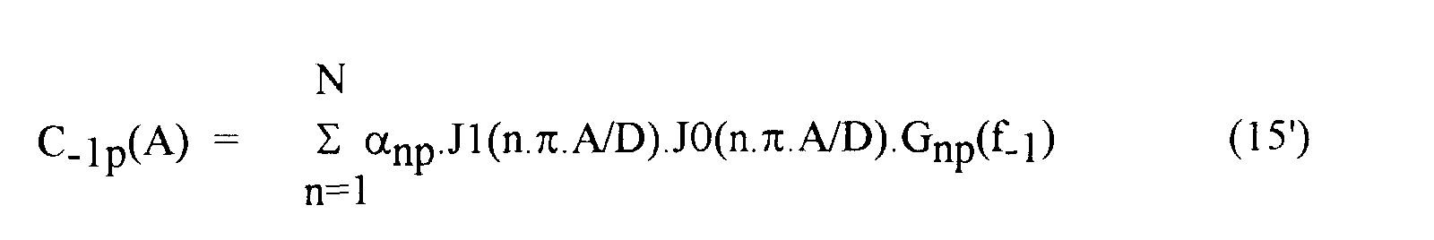


L'ordre 0, 1, 2 ou N d'une fonction de Bessel J0, J1, J2 ou JN est choisi de façon à correspondre à la valeur absolue du coefficient entier de combinaison d'une fréquence porteuse f-1 ou f1 dans la fréquence fi de la composante d'intermodulation d'amplitude Ci. L'ordre |i| de chaque composante d'intermodulation Ci correspond donc à la somme des ordres 0, 1, 2 ou N des fonctions de Bessel J0, J1, J2 ou JN impliquées dans chaque formule.The order 0, 1, 2 or N of a Bessel function J0, J1, J2 or JN is chosen so as to correspond to the absolute value of the integer coefficient of combination of a carrier frequency f -1 or f 1 in the frequency f i of the intermodulation component of amplitude C i . The order | i | of each intermodulation component C i therefore corresponds to the sum of the orders 0, 1, 2 or N of the Bessel functions J0, J1, J2 or JN involved in each formula.
Dans le cas général où le signal d'entrée x comporte m composantes
fréquentielles (porteuses), d'amplitudes quelconques, notées A, B, ..., M, on obtient
une multitude de produits d'intermodulation ayant chacun une fréquence donnée par la
formule suivante :
L'amplitude Ci de chaque composante d'intermodulation de fréquence fi suit la
formulation générale suivante :


J|n| est la fonction de Bessel du premier type et d'ordre valeur absolue de n
(généralisation).The amplitude C i of each frequency intermodulation component f i follows the following general formulation:
J | n | is the Bessel function of the first type and of absolute value order of n (generalization).
La figure 20 illustre ainsi une réalisation sophistiquée de moyens de calcul MM de composantes d'intermodulation développée à partir de ces formules de modèle à mémoire.FIG. 20 thus illustrates a sophisticated embodiment of MM calculation means of intermodulation components developed from these model formulas to memory.
On a représenté schématiquement sous forme de tableau de filtres élémentaires connectés en série horizontalement pour calculer le produit des fonctions de Bessel J|α| généralisées, modulées par l'amplitude des composantes A, B, ..., M du signal multi-porteuse. Chaque résultat horizontal est ensuite additionné avec les autres résultats horizontaux du tableau et avec les résultats d'un tableau similaire pour les composantes en quadratures avant de fournir en sortie l'amplitude d'une harmonique Yα,β,...,µ. We schematically represent in the form of an array of elementary filters connected in series horizontally to calculate the product of Bessel functions J | α | generalized, modulated by the amplitude of the components A, B, ..., M of the signal multi-carrier. Each horizontal result is then added with the others horizontal results of the table and with the results of a similar table for the quadrature components before outputting the amplitude of a harmonic Yα, β, ..., µ.
Sur cet exemple de réalisation sophistiqué, on voit que à partir d'une porteuse centrale B et de deux porteuses latérales A et M on obtient, outre la porteuse amplifiée Y010 de fréquence fB, au moins neuf produits d'intermodulation Y20-1, Y2-10, Y11-1, Y02-1, Y1-11, Y-120, Y-111, Y0-12 et Y-102 aux environs immédiats de la fréquence centrale fB.On this sophisticated embodiment, we see that from a central carrier B and two lateral carriers A and M we obtain, in addition to the amplified carrier Y 010 of frequency f B , at least nine intermodulation products Y 20- 1 , Y 2-10 , Y 11-1 , Y 02-1 , Y 1-11 , Y -120 , Y -111 , Y 0-12 and Y -102 in the immediate vicinity of the center frequency f B.
On voit donc que le nombre de produits d'intermodulation croít exponentiellement avec le nombre m de porteuses, et que la réalisation d'une simulation pour un signal à plus de deux porteuses ne peut être détaillée dans la présente, l'homme de métier pouvant la concevoir en généralisant les calculs décrits pour deux porteuses.We therefore see that the number of intermodulation products increases exponentially with the number m of carriers, and that the realization of a simulation for a signal with more than two carriers cannot be detailed in the present, the skilled person can conceive it by generalizing the calculations described for two carriers.
Un facteur de qualité déterminant dans la conception et le choix d'un système d'amplification hyperfréquence est le rapport de l'amplitude C3 de la plus forte composante d'intermodulation en sortie et de l'amplitude C1 en sortie d'une composante porteuse.A determining quality factor in the design and choice of a microwave amplification system is the ratio of the amplitude C 3 of the strongest intermodulation component at output and of the amplitude C 1 at output of a carrier component.
Dans la présente ce facteur, appelé facteur de réjection d'intermodulation, est
exprimé par la formule suivante :
Plus le ratio P/I est élevé, plus la qualité du système est élevée, la porteuse C1 se distinguant mieux du bruit d'intermodulation représenté par C3.The higher the P / I ratio, the higher the quality of the system, the carrier C1 better distinguished from the intermodulation noise represented by C3.
Dans le domaine hyperfréquence, le facteur de réjection est généralement
exprimé en puissance, ce qui correspond au ratio suivant :
Sous forme quadratique le facteur de réjection d'intermodulation s'écrit sous la
forme suivante :
En utilisant les résultats précédents des équations 14', 14" et 16', 16" établies par Abuelma'atti, on s'aperçoit que le facteur de réjection d'intermodulation simulé pour un amplificateur hyperfréquence varie très peu selon la fréquence.Using the previous results of the equations 14 ', 14 "and 16', 16" established by Abuelma'atti, we see that the simulated intermodulation rejection factor for a microwave amplifier varies very little depending on the frequency.
En effet les correcteurs en fréquence Gn(fi) ont un faible effet de correction, la courbe des correcteurs Gn étant calculée à partir de mesures avec une seule porteuse, donc sans modulation de l'enveloppe d'entrée. En particulier, les facteurs de réjection d'intermodulation P/I ainsi calculés ne sont pas fonction de l'écart fréquentiel df des porteuses, contrairement aux effets de résonnance constatés et illustrés par exemple sur la figure 16. Indeed, the frequency correctors G n (f i ) have a weak correction effect, the curve of the correctors G n being calculated from measurements with a single carrier, therefore without modulation of the input envelope. In particular, the intermodulation rejection factors P / I thus calculated do not depend on the frequency difference df of the carriers, unlike the resonance effects observed and illustrated for example in FIG. 16.
Selon un premier mode de réalisation de l'invention, il est prévu précisément de mesurer des caractéristiques de réjection d'intermodulation et d'utiliser ces mesures pour corriger le signal y de sortie calculé à partir d'un modèle connu.According to a first embodiment of the invention, it is specifically provided measure intermodulation rejection characteristics and use these measures to correct the output signal y calculated from a known model.
Dans le développement qui va suivre, le signal y(t) calculé selon le modèle d'Abuelma'atti est comparé à un signal z(t) comportant des composantes d'intermodulation telles que réellement mesurées. Une telle comparaison fournit la valeur d'un signal u(t) de modulation qui sera simulée par un filtre de modulation selon l'invention.In the following development, the signal y (t) calculated according to the model of Abuelma'atti is compared to a signal z (t) comprising components intermodulation as actually measured. Such a comparison provides the value of a modulation signal u (t) which will be simulated by a modulation filter according to the invention.
La figure 21 schématise un premier mode de réalisation de dispositif selon l'invention, qui comporte un tel filtre 14 de modulation. Le filtre 14 a une fonction de transfert E(f, H) qui calcule le signal u en fonction du signal d'entrée. Le signal y du modèle connu 11 est alors corrigé par le signal modulateur u pour fournir un signal z qui reproduit les distorsions de modulation effectivement mesurées.Figure 21 shows schematically a first embodiment of the device according to the invention, which includes such a modulation filter 14. The filter 14 has a function of transfer E (f, H) which calculates the signal u according to the input signal. The y signal of known model 11 is then corrected by the modulator signal u to provide a signal z which reproduces the modulation distortions actually measured.
Le développement suivant permet d'établir un exemple de relations permettant de construire la fonction de transfert E(f, H) du filtre IMF de calcul des intermodulations.The following development makes it possible to establish an example of relations allowing build the transfer function E (f, H) of the IMF filter for calculating intermodulations.
On constate d'abord que le signal modulateur u est utile seulement si le signal d'entrée a une enveloppe X modulée en amplitude. En effet, lorsque le signal d'entrée x n'est pas modulé, le modèle connu 11 a un signal de sortie y qui simule convenablement la réponse de l'amplificateur.We first note that the modulator signal u is useful only if the signal input has an amplitude modulated envelope X. Indeed, when the input signal x is not modulated, the known model 11 has an output signal y which simulates the amplifier's response appropriately.
L'invention prévoit précisément d'obtenir l'enveloppe du signal en prenant le
carré de la norme du signal x. En considérant l'équation 10 donnant l'enveloppe X du
signal biporteuse d'amplitude A et d'écart fréquentiel df, on obtient ainsi le carré X2 de
l'enveloppe suivant:
Le carré X2 donné par l'équation 20 se décompose en une amplitude A2
constante et un facteur de modulation donnés par l'équation suivante :
La figure 21 montre ainsi que le filtre 14 reçoit en entrée la valeur efficace X2(t) de l'enveloppe du signal d'entrée x. FIG. 21 thus shows that the filter 14 receives as input the effective value X 2 (t) of the envelope of the input signal x.
Selon l'invention, on considère que le signal modulateur u issu du filtre 14 doit
permettre d'écrire une formule de correction suivante :
De la sorte, en l'absence de modulation en entrée, le signal z simulé selon l'invention a une enveloppe Z qui correspond à l'enveloppe Y du signal de sortie y simulé par le modèle connu MNLSM ou MM, et le signal modulateur u est avantageusement nul.In this way, in the absence of input modulation, the signal z simulated according to the invention has an envelope Z which corresponds to the envelope Y of the output signal y simulated by the known model MNLSM or MM, and the modulator signal u is advantageously zero.
Par hypothèse, on exprime l'enveloppe U du signal modulateur, de façon
analogue à l'équation 20', comme le résultat de la transformation de la valeur efficace
X2 par la fonction de transfert E(f,H) qui dépend de la fréquence f et de l'amplitude H
des harmoniques h en entrée, c'est-à-dire sous la forme suivante :
Conventionnellement, E(0,A) a une valeur nulle, puisqu'il est inutile d'avoir un signal modulateur u quand il n'y a pas d'écart de fréquence de porteuses.Conventionally, E (0, A) has a zero value, since it is useless to have a modulator signal u when there is no carrier frequency difference.
On note K l'inconnue suivante :
Il est préférable d'écrire l'enveloppe U du signal modulateur donné par
l'équation 22, sous la forme complexe et exponentielle suivante :
De façon équivalente à l'équation (12), on préfère ici écrire l'enveloppe Y du
signal de sortie y du modèle connu sous la forme complexe et exponentielle suivante :
![]()
![]()
Dans le premier mode de réalisation on cherche à moduler uniquement l'amplitude des composantes d'intermodulation d'ordre 3 en modifiant au minimum l'amplitude des composantes porteuses (ordre 1) calculée par le modèle connu. Ceci s'obtient en minimisant la valeur de K, de sorte que les termes K.C-3, K.C1, K.C-1 et K.C3 soient négligeables. Dans ce cas, les deux lignes centrales de l'équation (25) indiquent que les composantes porteuses de fréquence f-1 et f1 ont bien une amplitude sensiblement égale à C-1 et C1, respectivement, dans le signal de sortie z modulé.In the first embodiment, it is sought to modulate only the amplitude of the intermodulation components of order 3 by modifying at least the amplitude of the carrier components (order 1) calculated by the known model. This is achieved by minimizing the value of K, so that the terms KC -3 , KC 1 , KC -1 and KC 3 are negligible. In this case, the two central lines of equation (25) indicate that the carrier components of frequency f -1 and f 1 do indeed have an amplitude substantially equal to C -1 and C 1 , respectively, in the output signal z module.
Dans un premier temps, on peut considérer que les amplitudes Ci de
composantes d'intermodulation ne dépendent pas de la fréquence fi, en supprimant les
corrections en fréquence Gnp,q(fi) prévues dans les formules de calcul 12' à 15". Le
calcul est alors simplifié, car les composantes symétriques en fréquence f-i et fi autour
des porteuses f-1 et f1 ont des amplitudes égales, selon l'identité suivante :
Les deux dernières lignes de l'équation (23) représentent les composantes de
fréquence f1 et f3 respectivement, ce qui permet de calculer le facteur de réjection P/I
qui a finalement la valeur suivante :
Numériquement, après avoir déterminé les amplitudes C1(A), C3(A) et C5(A) des composantes selon les méthodes connues, et après avoir mesuré la valeur du facteur de réjection P/I pour cette valeur d'amplitude A des porteuses, on résoud l'équation (26) pour déterminer la valeur de l'inconnue K.Numerically, after determining the amplitudes C 1 (A), C 3 (A) and C 5 (A) of the components according to known methods, and after having measured the value of the rejection factor P / I for this amplitude value At carriers, we solve equation (26) to determine the value of the unknown K.
Pour la résolution, on écrit de préférence l'inconnue K sous la forme complexe
suivante :
On fait varier l'argument pour calculer les valeurs de la norme |K| en fonction des valeurs de l'argument .We vary the argument to calculate the values of the norm | K | in function of the values of the argument .
La minimisation recherchée précédemment de la modification d'amplitude C-1 et C1 des porteuses f-1 et f1 est obtenue en retenant l'argument permettant d'obtenir la valeur minimale de la norme |K|.The minimization sought previously of the amplitude modification C -1 and C 1 of the carriers f -1 and f 1 is obtained by retaining the argument allowing to obtain the minimum value of the norm | K |.
La figure 18 permet de schématiser la systématique de mesures effectuées selon l'invention. On voit que les caractéristiques sont déterminées en effectuant une série de mesures avec un signal multi-porteuses f-1 et f1, en faisant varier à la fois l'amplitude A, A', A" des porteuses mais aussi l'écart fréquentiel df' = f1-f-1 des porteuses. En outre, on peut faire varier la fréquence de base f de la porteuse f1 ou f-1 servant de référence à l'écart fréquentiel dfFIG. 18 provides a diagram of the system of measurements carried out according to the invention. We see that the characteristics are determined by performing a series of measurements with a multi-carrier signal f -1 and f 1 , by varying both the amplitude A, A ', A "of the carriers but also the frequency difference df '= f 1 -f -1 of the carriers. In addition, we can vary the base frequency f of the carrier f 1 or f -1 serving as a reference for the frequency difference df
Pour chaque écart fréquentiel df, comme illustré sur la figure 16, on peut mesurer une courbe P/I caractéristique en fonction de l'amplitude A ou de la puissance de porteuse en entrée. En appliquant le calcul précédent, on obtient alors pour chaque écart fréquentiel df une courbe des valeurs d'inconnue K en fonction de l'amplitude A des porteuses. En faisant varier les écarts fréquentiels df, df', df", df‴, df"" des porteuses, on obtient ainsi un tableau de courbes de valeurs d'inconnues K. Ce tableau de valeurs K établit la trame de la fonction de transfert E(df,H) du filtre 14.For each frequency difference df, as illustrated in FIG. 16, we can measure a characteristic P / I curve as a function of amplitude A or power carrier at entry. By applying the previous calculation, we then obtain for each frequency deviation df a curve of unknown values K as a function of amplitude A carriers. By varying the frequency deviations df, df ', df ", df ‴, df" "of carriers, we thus obtain a table of curves of unknown values K. This table of values K establishes the frame of the transfer function E (df, H) of the filter 14.
La continuité de la fonction de transfert E(df,H) selon l'amplitude H des harmoniques h en entrée ou selon la puissance X2 de l'enveloppe du signal d'entrée x est obtenue en interpolant les valeurs discrètes du tableau des valeurs d'inconnues K.The continuity of the transfer function E (df, H) according to the amplitude H of the harmonics h at input or according to the power X 2 of the envelope of the input signal x is obtained by interpolating the discrete values from the table of values unknown K.
Les calculs et interpolations sont effectuées également pour toutes les valeurs d'écart fréquentiel df, les valeurs d'inconnue K pouvant également être interpolées entre les valeurs choisies df', df", df‴, df"" d'écart fréquentiel df.Calculations and interpolations are performed also for all values frequency deviation df, the unknown values K can also be interpolated between the chosen values df ', df ", df ‴, df" "of frequency difference df.
Un programme informatique exécute de préférence de tels calculs et stocke les valeurs d'inconnue K sous forme de matrice. A computer program preferably performs such calculations and stores the values of unknown K in the form of a matrix.
Dans un second temps, on considère que les amplitudes Ci des composantes d'intermodulation dépendent de la fréquence fi selon les formules complètes des équations 14' à 17". Il n'y a plus alors d'identité entre Ci et C-i.In a second step, we consider that the amplitudes C i of the intermodulation components depend on the frequency f i according to the complete formulas of equations 14 'to 17 ". There is no longer any identity between C i and C -i .
Les dissymétries en fréquence de la réponse de l'amplificateur peuvent alors être simulées par cette variante du premier mode de réalisation.The frequency asymmetries of the amplifier response can then be simulated by this variant of the first embodiment.
Dans ce cas, l'invention prévoit que la fonction de transfert E'(df,H) du filtre 14 peut être dissymétrique.In this case, the invention provides that the transfer function E '(df, H) of the filter 14 can be asymmetrical.
Les hypothèses de l'équation 22 et du calcul précédent sont alors modifiés
selon la formule complexe suivante :
Notons les termes de l'équation 22', sous la forme simplifiée suivante :
L'équation 23 est alors modifiée selon la formule suivante :
Notons Ci' les composantes modulées du signal de sortie z' modulé obtenu selon cette variante du premier mode de réalisation. Le signal de sortie z' est encore obtenu en modulant le signal y d'un modèle connu par un signal modulateur u' calculé par la fonction de transfert E' du filtre 34 de la figure 23. Ceci permet de distinguer les composantes C'i modulées selon l'invention, des composantes Ci calculées par le modèle sans mémoire MNLSM connu. Denote by C i 'the modulated components of the modulated output signal z' obtained according to this variant of the first embodiment. The output signal z 'is also obtained by modulating the signal y of a known model by a modulator signal u' calculated by the transfer function E 'of the filter 34 of FIG. 23. This makes it possible to distinguish the components C' i modulated according to the invention, components C i calculated by the model with no known MNLSM memory.
Selon les équations 21, 24' et 28 précédentes, les composantes modulées ont
des amplitudes C-3', C-1', C1', C3' déterminées par les formules suivantes :
On obtient alors deux résultats plus complexes de facteurs de réjection
d'intermodulation, notés P/I+ et P/I-, selon que le facteur de réjection est mesuré sur
les fréquences f1 et f3 supérieures ou sur les fréquence f-1 et f-3 inférieures de
porteuse et d'intermodulation. Les deux facteurs de réjection ont les formes suivantes
On résoud ensuite, de façon connue, le système des deux équations 33 et 34 à deux inconnues K- et K+.Then, in a known manner, the system of the two equations 33 and 34 is solved with two unknowns K - and K + .
Ainsi quand l'amplificateur a une réponse dissymétrique autour des fréquences porteuses, il est prévu selon l'invention de mesurer des caractéristiques de réjection d'intermodulation, en prévoyant de mesurer les deux facteurs de réjection P/I+ supérieur et P/I- inférieur pour chaque amplitude A et écart fréquentiel df de porteuses, afin de simuler les distorsions de modulation en sortie.Thus when the amplifier has an asymmetrical response around the carrier frequencies, it is provided according to the invention to measure intermodulation rejection characteristics, by providing for measuring the two rejection factors P / I + higher and P / I - lower for each amplitude A and frequency difference df of carriers, in order to simulate the distortions of modulation at output.
Un second mode de réalisation de l'invention permet de simuler le second effet de distorsion d'intermodulation.A second embodiment of the invention makes it possible to simulate the second effect intermodulation distortion.
Le second effet observé est la variation du gain des porteuses en fonction de la fréquence d'enveloppe df/2, illustré par exemple sur la figure 17. En mesurant le gain de l'amplificateur pour une porteuse f1 d'amplitude C1 de sortie, en présence d'une autre porteuse f-1, on se rend compte que le gain peut avoir des variations importantes, en fonction de l'écart fréquentiel df des deux porteuses f-1 et f1. The second effect observed is the variation of the gain of the carriers as a function of the envelope frequency df / 2, illustrated for example in FIG. 17. By measuring the gain of the amplifier for a carrier f 1 of amplitude C 1 of output, in the presence of another carrier f -1 , we realize that the gain can have significant variations, depending on the frequency difference df of the two carriers f -1 and f 1 .
L'invention prévoit d'ajuster les amplitudes C1 et C-1 de sortie des porteuses calculée par un modèle connu, en tenant compte de mesures de caractéristiques C1/C-1 d'interaction de porteuses.The invention provides for adjusting the amplitudes C 1 and C -1 of the carrier output calculated by a known model, taking into account measurements of characteristics C1 / C-1 of carrier interaction.
De préférence, l'ajustement du second mode de réalisation se combine à l'ajustement des principales composantes d'intermodulation C3 et C-3 prévu dans le premier mode de réalisation de l'invention, précédemment exposé. On peut prévoir en outre un ajustement des composantes C5 et C5 d'intermodulation secondaires.Preferably, the adjustment of the second embodiment is combined with the adjustment of the main intermodulation components C 3 and C- 3 provided for in the first embodiment of the invention, described above. It is also possible to provide for an adjustment of the secondary intermodulation components C 5 and C 5 .
Dans le second mode de réalisation de dispositif selon l'invention, l'ajustement est effectué en corrigeant le signal de sortie y, ou de préférence le signal modulé z ou z', par un signal de correction v issu d'un filtre 37 ayant une fonction de transfert F de correction.In the second embodiment of the device according to the invention, the adjustment is performed by correcting the output signal y, or preferably the modulated signal z or z ', by a correction signal v coming from a filter 37 having a transfer function F of correction.
La fonction de transfert F est calculée, de façon analogue à la fonction E, en
supposant une correction des composantes modulées Ci' formulées précédemment aux
équations 29 à 32 selon les formules suivantes :
F est la fonction de transfert de correction exprimée en fonction de la fréquence de modulation de l'enveloppe, c'est-à-dire de l'écart fréquentiel df des porteuses d'amplitude A en entrée.F is the correction transfer function expressed as a function of the envelope modulation frequency, i.e. the frequency difference df of amplitude A carriers at input.
Les composantes C3", C-3", C1" et C-1" sont appelées composantes corrigées.The components C 3 ", C -3 ", C 1 "and C -1 " are called corrected components.
Les équations 35 à 38 forment un système de quatre équations à quatre inconnues K+, K-, L+, L- qui est résolu de façon connue. La résolution des deux dernières équations 37 et 38 fournit les valeurs des inconnues de correction L+ et L-.Equations 35 to 38 form a system of four equations with four unknowns K + , K - , L + , L - which is solved in a known manner. The resolution of the last two equations 37 and 38 provides the values of the correction unknowns L + and L - .
La mesure précise des amplitudes réelles des composantes f3, f-3 d'intermodulation d'ordre 3 et des porteuses f1, f-1 permet ainsi, après calcul des composantes C-5, C-3, C-1, C1, C3, C5 d'ordre 1, 3 et 5 selon un modèle connu, de calculer les fonctions de transfert de modulation E(df,A) et de correction F(df,A). The precise measurement of the actual amplitudes of the order 3 intermodulation components f 3 , f -3 and of the carriers f 1 , f -1 thus allows, after calculation of the components C -5 , C -3 , C -1 , C 1 , C 3 , C 5 of order 1, 3 and 5 according to a known model, to calculate the transfer functions of modulation E (df, A) and of correction F (df, A).
De telles mesures complètes d'amplitudes de composantes en sortie d'un amplificateur comportant à la fois des mesures de réjection de composante d'intermodulation d'ordre 3 et 5 en sortie et des mesures d'interaction de porteuses permettent ainsi de simuler complètement la réponse en signal avec les distorsions dues à l'effet de mémoire d'enveloppe d'un amplificateur non-linéaire à mémoire. On notera cependant que des mesures partielles comme les mesures de réjection C1/C3 d'intermodulation d'ordre 3 ou les mesures d'interaction de porteuses C1/C-1 suffisent à caractériser certains effets de distorsion d'intermodulation.Such complete measurements of amplitudes of components at the output of a amplifier comprising both component rejection measurements intermodulation of order 3 and 5 at output and carrier interaction measurements thus allow to fully simulate the signal response with distortions due to the envelope memory effect of a non-linear amplifier with memory. We note, however, that partial measures such as rejection measures C1 / C3 3 order intermodulation or C1 / C-1 carrier interaction measurements are sufficient to characterize certain intermodulation distortion effects.
Un deuxième mode de réalisation permet la validation du modèle par la mesure du rapport signal à bruit en présence d'un nombre élevé de porteuses dont la densité spectrale de puissance DSP est modélisée par un bruit blanc.A second embodiment allows validation of the model by measurement signal-to-noise ratio in the presence of a high number of carriers whose density DSP power spectral is modeled by white noise.
Les figures 19A et 19B illustrent ainsi un diagramme fréquentiel de bruit, respectivement appliqué en entrée et mesuré en sortie d'un amplificateur non-linéaire à mémoire pour le caractériser.FIGS. 19A and 19B thus illustrate a frequency diagram of noise, respectively applied at the input and measured at the output of a non-linear amplifier memory to characterize it.
Selon l'invention, comme illustré sur la figure 19A, on applique un bruit blanc ayant une densité spectrale de puissance DSP de niveau NP constant dans une bande de fréquence BW sauf dans une fenêtre BH de fréquence dans laquelle le bruit est absent. Ce signal d'entrée bien qu'ayant une densité spectrale constante est d'amplitude variable. Il permet donc de mesurer les distorsions de modulation apparaissant en sortie de l'amplificateur. Les distorsions apparaissent en sortie de l'amplificateur sous forme de report de bruit dans la fenêtre BH précédemment définie.According to the invention, as illustrated in FIG. 19A, white noise is applied having a DSP power spectral density of constant NP level in a band of frequency BW except in a window BH of frequency in which the noise is absent. This input signal although having a constant spectral density is of amplitude variable. It therefore makes it possible to measure the modulation distortions appearing in amplifier output. The distortions appear at the amplifier output under form of noise transfer in the previously defined BH window.
La caractérisation de l'amplificateur consiste à mesurer sa capacité à limiter le report de bruit dans la fenêtre BH en mesurant la différence de niveau de bruit NPR en sortie, dans la bande de fréquence BW et dans la fenêtre BH.The characterization of the amplifier consists in measuring its capacity to limit the noise transfer in the BH window by measuring the difference in noise level NPR as output, in the BW frequency band and in the BH window.
Ces mesures de caractéristiques sont effectuées à différents niveaux NP de bruit et sont introduites dans le simulateur afin qu'il reproduise ces caractéristiques de bruit selon les conditions de fonctionnement.These characteristic measurements are carried out at different levels NP of noise and are introduced into the simulator so that it reproduces these characteristics of noise depending on operating conditions.
Un troisième mode de contrôle de la validité du modèle consiste à mesurer le taux d'erreur binaire lors d'une amplification de porteuses modulées.A third mode of checking the validity of the model consists in measuring the bit error rate during amplification of modulated carriers.
La figure 24 illustre un banc de test utilisé pour établir selon l'invention des mesures de caractéristiques d'amplificateur DUT non-linéaire à mémoire. Ce banc de test, dont la compréhension du fonctionnement est à la portée de l'homme de métier, comporte notamment un bloc 10 de génération de signal modulé en amplitude avec, par exemple, deux générateurs SG1 et SG2 de fréquences pouvant être distinctes pour appliquer un signal multi-porteuses au dispositif DUT amplificateur à caractériser. Il comporte en outre un bloc 20 de mesure de bruit avec un générateur NG de bruit blanc à fenêtre et éventuellement un bloc 30 de mesure de taux d'erreur binaire avec un générateur MOD de signaux modulés par un message binaire aléatoire et un comparateur Comp du signal d'origine et du signal de retour de l'amplificateur.FIG. 24 illustrates a test bench used to establish, according to the invention, non-linear DUT amplifier characteristic measurements with memory. This bench of test, whose understanding of the operation is within the reach of the skilled person, in particular comprises an amplitude modulated signal generation block 10 with, for example, two generators SG1 and SG2 of frequencies which can be distinct for apply a multi-carrier signal to the DUT amplifier device to be characterized. he further includes a noise measurement block 20 with an NG noise generator white with window and possibly a block 30 for measuring the bit error rate with a MOD generator of signals modulated by a random binary message and a comparator Comp of the original signal and the amplifier return signal.
La figure 25 illustre enfin un diagramme des fichiers de caractéristiques mis en oeuvre par un programme informatique pour simuler l'amplification non-linéaire selon le procédé de l'invention.FIG. 25 finally illustrates a diagram of the characteristics files set up work by a computer program to simulate the non-linear amplification according to the method of the invention.
Le programme Pro fait ainsi appel à un fichier 203 stockant des résultats de mesures de caractéristiques AP statiques, c'est-à-dire de courbes C,Φ ou de courbes P,Q établies à amplitude constante (de façon connue).The Pro program thus calls up a file 203 storing results of measurements of static AP characteristics, i.e. of C, Φ curves or curves P, Q established at constant amplitude (in a known manner).
Le programme Pro fait encore appel à une série de fichiers 205, 206, 207 stockant des résultats de mesures de caractéristiques P/I dynamiques comme des courbes C1/C3 de réjection d'intermodulation ou des courbes C1/C-1 d'interaction de porteuses. Chaque fichier 205 ou 206 ou 207 de la série est établi par exemple pour un écart fréquentiel df de porteuses.The Pro program still uses a series of files 205, 206, 207 storing dynamic P / I characteristic measurement results as intermodulation rejection curves C1 / C3 or interaction interaction curves C1 / C-1 carriers. Each file 205 or 206 or 207 of the series is established for example for a frequency difference df of carriers.
Le programme est lancé après avoir introduit des données générales Dat sur l'amplificateur à simuler.The program is launched after having entered general data on the amplifier to simulate.
En sortie, le programme Pro fournit un fichier 204 des coefficients α de suite de fonctions de transfert directes, notamment de fonctions de Bessel. Il fournit surtout selon l'invention des fichiers 208, 209 contenant les données des fonctions de transfert de modulation E et de correction F précitées.As output, the Pro program provides a file 204 of the coefficients α in succession direct transfer functions, in particular Bessel functions. It mainly provides according to the invention files 208, 209 containing the data of the transfer functions E modulation and F correction above.
La figure 26 représente un exemple de schéma d'étape de processus mis en oeuvre par un tel programme Pro.Figure 26 shows an example of process step diagram implemented works through such a Pro program.
La réalisation de dispositif selon l'invention est effectuée de préférence sous forme de programme informatique dont les fonctions correspondent aux blocs schématisés à titre d'exemple sur les figures 20 à 24.The device according to the invention is preferably produced under form of computer program whose functions correspond to blocks shown schematically by way of example in FIGS. 20 to 24.
D'autres applications variantes de réalisation et améliorations pourront être mises en oeuvre par l'homme de métier sans sortir du cadre de la présente invention, dont la portée est définie par les revendications ci-après.Other applications, variant embodiments and improvements may be implemented by a person skilled in the art without departing from the scope of the present invention, the scope of which is defined by the claims below.
Claims (17)
Applications Claiming Priority (2)
| Application Number | Priority Date | Filing Date | Title |
|---|---|---|---|
| FR9710052 | 1997-08-01 | ||
| FR9710052A FR2766992B1 (en) | 1997-08-01 | 1997-08-01 | METHOD FOR SIMULATING A NON-LINEAR ENVELOPE MEMORY AMPLIFIER |
Publications (1)
| Publication Number | Publication Date |
|---|---|
| EP0896426A1 true EP0896426A1 (en) | 1999-02-10 |
Family
ID=9510071
Family Applications (1)
| Application Number | Title | Priority Date | Filing Date |
|---|---|---|---|
| EP98401958A Withdrawn EP0896426A1 (en) | 1997-08-01 | 1998-07-30 | Method for simulating a nonlinear amplifier with envelope memory |
Country Status (4)
| Country | Link |
|---|---|
| US (1) | US6216100B1 (en) |
| EP (1) | EP0896426A1 (en) |
| JP (1) | JPH11191716A (en) |
| FR (1) | FR2766992B1 (en) |
Cited By (1)
| Publication number | Priority date | Publication date | Assignee | Title |
|---|---|---|---|---|
| WO2001003287A1 (en) * | 1999-06-30 | 2001-01-11 | Wireless Systems International Limited | Reducing distortion of signals |
Families Citing this family (13)
| Publication number | Priority date | Publication date | Assignee | Title |
|---|---|---|---|---|
| US6801086B1 (en) * | 2002-04-03 | 2004-10-05 | Andrew Corporation | Adaptive digital pre-distortion using amplifier model that incorporates frequency-dependent non-linearities |
| JP4394409B2 (en) * | 2003-09-25 | 2010-01-06 | 株式会社日立国際電気 | Predistortion type amplifier with distortion compensation function |
| US7071777B2 (en) * | 2003-12-02 | 2006-07-04 | Motorola, Inc. | Digital memory-based predistortion technique |
| US20060039498A1 (en) * | 2004-08-19 | 2006-02-23 | De Figueiredo Rui J P | Pre-distorter for orthogonal frequency division multiplexing systems and method of operating the same |
| US7856483B2 (en) | 2004-12-10 | 2010-12-21 | Microsoft Corporation | Information management systems with time zone information, including event scheduling processes |
| CN1983851B (en) * | 2006-06-16 | 2010-07-28 | 华为技术有限公司 | Method for supporting multi-power by amplifier and radio-frequency module |
| EP1968205A1 (en) * | 2007-02-28 | 2008-09-10 | Nederlandse Organisatie voor toegepast- natuurwetenschappelijk onderzoek TNO | Signal quality determination in cable networks |
| JP4918572B2 (en) * | 2009-07-02 | 2012-04-18 | 株式会社日立国際電気 | Predistortion type amplifier with distortion compensation function |
| JP5903758B2 (en) * | 2010-09-08 | 2016-04-13 | ソニー株式会社 | Signal processing apparatus and method, program, and data recording medium |
| US9577855B1 (en) | 2011-07-13 | 2017-02-21 | Softronics, Ltd. | Channelized multicarrier digitizer |
| FR2999364A1 (en) * | 2012-12-10 | 2014-06-13 | Centre Nat Etd Spatiales | METHOD FOR PREDICTIVE EVALUATION OF THE INTERMODULATION POWER IN AN ELECTRONIC DEVICE |
| US20150160279A1 (en) * | 2013-12-09 | 2015-06-11 | Qualcomm Incorporated | Quantitative characterization of nonlinearity and memory effect in nonlinear circuits |
| US20170024495A1 (en) * | 2015-07-21 | 2017-01-26 | Positive Grid LLC | Method of modeling characteristics of a musical instrument |
Citations (1)
| Publication number | Priority date | Publication date | Assignee | Title |
|---|---|---|---|---|
| US5579342A (en) * | 1994-09-22 | 1996-11-26 | Her Majesty The Queen In Right Of Canada As Represented By The Minister Of Communications | Pre-compensated frequency modulation (PFM) |
-
1997
- 1997-08-01 FR FR9710052A patent/FR2766992B1/en not_active Expired - Fee Related
-
1998
- 1998-07-29 US US09/124,430 patent/US6216100B1/en not_active Expired - Fee Related
- 1998-07-30 EP EP98401958A patent/EP0896426A1/en not_active Withdrawn
- 1998-08-03 JP JP10251762A patent/JPH11191716A/en not_active Abandoned
Patent Citations (1)
| Publication number | Priority date | Publication date | Assignee | Title |
|---|---|---|---|---|
| US5579342A (en) * | 1994-09-22 | 1996-11-26 | Her Majesty The Queen In Right Of Canada As Represented By The Minister Of Communications | Pre-compensated frequency modulation (PFM) |
Non-Patent Citations (4)
| Title |
|---|
| BOSCH W ET AL: "MEASUREMENT AND SIMULATION OF MEMORY EFFECTS IN PREDISTORTION LINEARIZERS", IEEE TRANSACTIONS ON MICROWAVE THEORY AND TECHNIQUES, vol. 37, no. 12, 1 December 1989 (1989-12-01), pages 1885 - 1890, XP000173168 * |
| CARDINAL J -S ET AL: "A NEW ADAPTIVE DOUBLE ENVELOPE FEEDBACK (ADEF) LINEARIZER FOR SOLIDSTATE POWER AMPLIFIERS", IEEE TRANSACTIONS ON MICROWAVE THEORY AND TECHNIQUES, vol. 43, no. 7, PART 01, 1 July 1995 (1995-07-01), pages 1508 - 1515, XP000514134 * |
| GHADERI M ET AL: "FAST ADAPTIVE POLYNOMIAL I AND Q PREDISTORTER WITH GLOBAL OPTIMISATION", IEE PROCEEDINGS: COMMUNICATIONS, vol. 143, no. 2, 1 April 1996 (1996-04-01), pages 78 - 86, XP000592638 * |
| KARAM G ET AL: "IMPROVED DATA PREDISTORTION USING INTERSYMBOL INTERPOLATION", WORLD PROSPERITY THROUGH COMMUNICATIONS, BOSTON, JUNE 11 - 14, 1989, vol. VOL. 1, no. -, 11 June 1989 (1989-06-11), INSTITUTE OF ELECTRICAL AND ELECTRONICS ENGINEERS, pages 286 - 291, XP000075470 * |
Cited By (2)
| Publication number | Priority date | Publication date | Assignee | Title |
|---|---|---|---|---|
| WO2001003287A1 (en) * | 1999-06-30 | 2001-01-11 | Wireless Systems International Limited | Reducing distortion of signals |
| US7106806B1 (en) | 1999-06-30 | 2006-09-12 | Andrew Corporation | Reducing distortion of signals |
Also Published As
| Publication number | Publication date |
|---|---|
| US6216100B1 (en) | 2001-04-10 |
| JPH11191716A (en) | 1999-07-13 |
| FR2766992B1 (en) | 2000-12-29 |
| FR2766992A1 (en) | 1999-02-05 |
Similar Documents
| Publication | Publication Date | Title |
|---|---|---|
| EP0896426A1 (en) | Method for simulating a nonlinear amplifier with envelope memory | |
| EP0797294A1 (en) | Method for correcting non-linear distortion of an amplifier and radio transmitter using such method | |
| CA2256177A1 (en) | Digital linear amplifier, methods and system | |
| EP0797293A1 (en) | Method for correcting non-linear distortion of an amplifier and radio transmitter using such method | |
| FR2494059A1 (en) | QUICK ACQUISITION CARRIER DEMODULATION METHOD AND DEVICE | |
| EP2341614B1 (en) | Linearization device for a power amplifier | |
| Sombrin | On the formal identity of EVM and NPR measurement methods: Conditions for identity of error vector magnitude and noise power ratio | |
| EP0073869B1 (en) | Data receiving apparatus with listener echo canceller | |
| EP0044598A1 (en) | Cancelling arrangement for a composite echo signal | |
| EP3785367A1 (en) | System and method of baseband linearisation for a class g radiofrequency power amplifier | |
| EP3835811B1 (en) | Method for uncoupling of signals in transmitting/receiving systems | |
| WO2017186861A1 (en) | Method and device for reducing noise in a module signal | |
| FR3087306A1 (en) | SELF-CALIBRATED MULTI-WAY TRANSMISSION SYSTEM FOR SATELLITE PAYLOAD | |
| FR2541058A1 (en) | HIGH FREQUENCY AMPLIFIER LINEARIZATION DEVICE HAVING COMPLEX NON-LINEARITY COEFFICIENTS | |
| FR2717294A1 (en) | Dynamic musical sound synthesis method e.g. for instrument, voice | |
| EP3503385B1 (en) | Low-complexity time synchronisation in a loop for calculating digital predistortion | |
| CA2218925A1 (en) | Quadrature modulator operating defect estimator and modulation stage using this estimator | |
| FR2595895A1 (en) | DOUBLE DIGITAL DEMODULATOR | |
| FR3054339A1 (en) | CORRECTION METHOD WITHOUT CALIBRATING A DEFECT INTRODUCED BY A SCANNING SYSTEM AND ASSOCIATED DEVICES | |
| EP2114045B1 (en) | Cancelling out of the imperfections of a modulator | |
| FR3003114A1 (en) | METHOD AND SYSTEM FOR TESTING AUDIO DEVICE | |
| WO1991012697A1 (en) | Method and device for single measurement to display and qualify the linearity of a transmission channel | |
| EP2028810A1 (en) | Correction of distortions in a transmission chain | |
| FR2540309A1 (en) | Linearisation device for a high-frequency amplifier with amplitude non-linearity | |
| CN112436906B (en) | Wireless modulation signal modulation quality parameter calibration equipment |
Legal Events
| Date | Code | Title | Description |
|---|---|---|---|
| PUAI | Public reference made under article 153(3) epc to a published international application that has entered the european phase |
Free format text: ORIGINAL CODE: 0009012 |
|
| AK | Designated contracting states |
Kind code of ref document: A1 Designated state(s): DE FR GB IT |
|
| AX | Request for extension of the european patent |
Free format text: AL;LT;LV;MK;RO;SI |
|
| 17P | Request for examination filed |
Effective date: 19990722 |
|
| AKX | Designation fees paid |
Free format text: DE FR GB IT |
|
| GRAP | Despatch of communication of intention to grant a patent |
Free format text: ORIGINAL CODE: EPIDOSNIGR1 |
|
| RAP1 | Party data changed (applicant data changed or rights of an application transferred) |
Owner name: FRANCE TELECOM S.A. |
|
| STAA | Information on the status of an ep patent application or granted ep patent |
Free format text: STATUS: THE APPLICATION IS DEEMED TO BE WITHDRAWN |
|
| 18D | Application deemed to be withdrawn |
Effective date: 20080110 |