EP0896182B1 - Connector system - Google Patents
Connector system Download PDFInfo
- Publication number
- EP0896182B1 EP0896182B1 EP97112309A EP97112309A EP0896182B1 EP 0896182 B1 EP0896182 B1 EP 0896182B1 EP 97112309 A EP97112309 A EP 97112309A EP 97112309 A EP97112309 A EP 97112309A EP 0896182 B1 EP0896182 B1 EP 0896182B1
- Authority
- EP
- European Patent Office
- Prior art keywords
- shutter
- tubular body
- upstream
- downstream
- fixed
- Prior art date
- Legal status (The legal status is an assumption and is not a legal conclusion. Google has not performed a legal analysis and makes no representation as to the accuracy of the status listed.)
- Expired - Lifetime
Links
Images


Classifications
-
- F—MECHANICAL ENGINEERING; LIGHTING; HEATING; WEAPONS; BLASTING
- F16—ENGINEERING ELEMENTS AND UNITS; GENERAL MEASURES FOR PRODUCING AND MAINTAINING EFFECTIVE FUNCTIONING OF MACHINES OR INSTALLATIONS; THERMAL INSULATION IN GENERAL
- F16L—PIPES; JOINTS OR FITTINGS FOR PIPES; SUPPORTS FOR PIPES, CABLES OR PROTECTIVE TUBING; MEANS FOR THERMAL INSULATION IN GENERAL
- F16L37/00—Couplings of the quick-acting type
- F16L37/28—Couplings of the quick-acting type with fluid cut-off means
- F16L37/30—Couplings of the quick-acting type with fluid cut-off means with fluid cut-off means in each of two pipe-end fittings
- F16L37/32—Couplings of the quick-acting type with fluid cut-off means with fluid cut-off means in each of two pipe-end fittings at least one of two lift valves being opened automatically when the coupling is applied
-
- Y—GENERAL TAGGING OF NEW TECHNOLOGICAL DEVELOPMENTS; GENERAL TAGGING OF CROSS-SECTIONAL TECHNOLOGIES SPANNING OVER SEVERAL SECTIONS OF THE IPC; TECHNICAL SUBJECTS COVERED BY FORMER USPC CROSS-REFERENCE ART COLLECTIONS [XRACs] AND DIGESTS
- Y10—TECHNICAL SUBJECTS COVERED BY FORMER USPC
- Y10T—TECHNICAL SUBJECTS COVERED BY FORMER US CLASSIFICATION
- Y10T137/00—Fluid handling
- Y10T137/8593—Systems
- Y10T137/87917—Flow path with serial valves and/or closures
- Y10T137/87925—Separable flow path section, valve or closure in each
- Y10T137/87941—Each valve and/or closure operated by coupling motion
- Y10T137/87949—Linear motion of flow path sections operates both
- Y10T137/87957—Valves actuate each other
-
- Y—GENERAL TAGGING OF NEW TECHNOLOGICAL DEVELOPMENTS; GENERAL TAGGING OF CROSS-SECTIONAL TECHNOLOGIES SPANNING OVER SEVERAL SECTIONS OF THE IPC; TECHNICAL SUBJECTS COVERED BY FORMER USPC CROSS-REFERENCE ART COLLECTIONS [XRACs] AND DIGESTS
- Y10—TECHNICAL SUBJECTS COVERED BY FORMER USPC
- Y10T—TECHNICAL SUBJECTS COVERED BY FORMER US CLASSIFICATION
- Y10T137/00—Fluid handling
- Y10T137/8593—Systems
- Y10T137/87917—Flow path with serial valves and/or closures
- Y10T137/87925—Separable flow path section, valve or closure in each
- Y10T137/87965—Valve- or closure-operated by coupling motion
Definitions
- the subject of the present invention is a connector system for coupling a line of fluid under pressure to a line receiving said fluid, comprising an upstream tubular body capable of being connected to the fluid line under pressure, a downstream tubular body pluggable into the tubular body upstream and able to be connected to the receiving pipe, and means for locking of the insertion of the downstream tubular body into the tubular body upstream.
- Connector systems of this type currently find many industrial and medical applications, especially for medical and dental equipment.
- connectors are known from documents US-A-3,918,485 and EP-A-0 172 996.
- the fluid leaks that occur at the logging in and out can be annoying, for example for health or safety reasons. And when the system connector is intended for the mixed connection of equipment using from fluid lines and to electrical lines these leaks can constitute a serious risk, both at connection and at disconnection, not to mention that the connection elements affected by the leaks must be cleaned or even reconditioned to be able to reconnect reliable.
- the object of the present invention is to remedy these drawbacks. She has also aim to offer a simple and easy to make connector system economically.
- the only functions of plugging the downstream tubular body into the upstream tubular body and withdrawal of said downstream tubular body from the body tubular upstream allow the opening of the second shutter before that the first shutter and closing the first shutter before closing the second shutter.
- the risk of leakage is eliminated. of the variations in the pressure of the pressurized fluid have no effect on the controlled function of the system.
- the connector system thus ensures its function for a wide range of fluid pressures under pressure.
- the connection as well as disconnection are done without brutal reactions on the upstream tubular body or on the downstream tubular body and the locking of plugging can be simplified. Any wrong move is impossible and the absence of leakage makes the system particularly applicable to the mixed connection of fluid lines combined with that of conductors electrical and / or fiber optic.
- the first support means comprise a pusher and a tubular wall attached to the first shutter downstream thereof
- the second means support include a pusher attached to the second shutter upstream of the latter and capable of meeting the pusher fixed to the first shutter
- the third support means are constituted by an upstream edge of the body downstream tubular able to meet the downstream tubular wall fixed to the first shutter, the relative arrangement of these support means being such that at the insertion of the downstream tubular body into the upstream tubular body the pusher attached to the second shutter first meets the pusher attached to the first obturator, then the upstream edge of the downstream tubular body meets the wall tubular attached to the first obturator.
- the first support means comprise a fixed pusher to the first shutter downstream thereof
- the second support means include a pusher attached to the second shutter upstream thereof and able to meet the pusher attached to the first shutter
- the third support means comprise a stop fixed in the downstream tubular body and able to meet the second shutter when it is far from its seat.
- the pusher attached to the first shutter has a downstream end set back from a downstream edge of the upstream tubular body, and the pusher attached to the second shutter at an upstream end set back from a upstream edge of the downstream tubular body.
- one of the upstream and downstream tubular body is fixed in a base provided with a recess surrounding the tubular body and in which is formed a attachment groove
- the other tubular body is fixed in a plug suitable for be introduced into the recess and provided with elastic tabs snap notches in the hanging groove, inserting the plug in the recess of the base until the catch clicks in the attachment groove determining the insertion of the downstream tubular body into the upstream tubular body.
- the sheet may include mobile support means to constrain the elastic tabs against their elasticity, to allow release without force the catch notches of the hooking groove and separate the plug from the base and therefore remove the downstream tubular body from the body upstream tubular.
- a control ring will be preferably mounted movable longitudinally on the plug, the means mobile support being connected to this ring. Connection and disconnection of the connector system is then ensured by a simple "push-pull" operation on the control ring. Locking the body plug downstream tubular in the upstream tubular body is quick and maximum reliability, and handling is very simple even in a confined environment.
- a control ring can also be mounted movable longitudinally on the plug, the elastic tabs being connected to this ring.
- ramps integral with the plug can force the notches for snapping the elastic tabs into the hooking groove of the base.
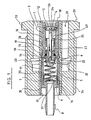
- Figures 1 and 2 are two longitudinal sections of the constituent elements of the first embodiment.
- Figures 3, 4 and 5 are longitudinal sections illustrating the operation of this first embodiment.
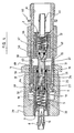
- Figures 6 and 7 are two longitudinal sections of the components of the second embodiment.
- the connector system shown in Figures 1 and 2 includes a body upstream tubular 1 and a downstream tubular body 2 able to be inserted in the upstream tubular body 1.
- the upstream tubular body 1 ( Figure 1), includes a main cylinder 3 comprising a downstream chamber 4 and an upstream chamber 5 between which a inclined shoulder forms a seat 6.
- a junction connector 8 In the upstream end 7 of the chamber 5 is screwed a junction connector 8 to a pressurized fluid line (not shown) and the downstream end 9 of this connector forms a cylindrical support bowl 10. In the end downstream of the downstream chamber 4 is placed an O-ring 11.
- the main cylinder 3 is fixed in a sleeve 12, for example in material insulating plastic.
- the fixing of the main cylinder 3 in the sleeve 12 is provided by a plurality of elastic strips 13 fixed on the periphery of the main cylinder 3 and bearing against an internal shoulder 14 of the sleeve 12.
- Longitudinal grooves 15 and 16 formed inside the sleeve 12 allow the passage of the elastic strips 13 during threading the main cylinder 3 into the sleeve 12, and a shoulder of counter-support 17 formed on the periphery of the main cylinder 3 opposite the lamellae 13 secures the shoulder 14 of the sleeve 12 between the strips 13 and the abutment shoulder 17.
- a first shutter 18 In the upstream chamber 5 of the main cylinder 3 is placed a first shutter 18 provided with an annular seal 19.
- the first shutter 18, longitudinally movable in the upstream chamber 5, is pressed against the seat 6 via the seal 19, under the action of a first elastic stress constituted by a compression spring 20 placed in upstream of said shutter.
- An upstream end 21 of the spring 20 is housed in the bowl 10 of the connector 8 and a downstream end 22 of said spring rests on a shoulder 23 of the shutter 18.
- First support means integral with the first shutter 18 are formed by a pusher 24 and a tubular wall 25 fixed downstream of the shutter 18 and extending into the downstream chamber 4 of the main cylinder 3.
- the pusher 24 has at its downstream end a support cone 26 and this end is set back from the downstream edge 58 of the downstream chamber 4 of the body main 3.
- the tubular wall 25 is provided with transverse openings upstream 27 and its outside diameter is such that it is capable of sliding against a cylindrical seat 28 provided in the main cylinder 3, downstream of the seat 6, when the shutter 18 is moved against the action of the spring 20.
- the upstream tubular body 1 is housed in a base 29 in which it is fixed for example by gluing an upstream part 30 of the sleeve 12.
- the base 29 includes a recess 31 surrounding the tubular body upstream 1 and in which a hooking groove 32 is formed.
- the base 29 includes a support flange 33 and a peripheral thread 34 by through which it can be attached to a distribution board (not represented).
- the downstream tubular body 2 ( Figure 2) comprises a main cylinder 35 comprising a downstream chamber 36 and an upstream chamber 37 of diameter outside as it can be inserted in the downstream chamber 4 of the cylinder main 3 of the upstream tubular body 1 and bear against the O-ring 11 of it.
- the junction of chambers 36 and 37 forms an inclined shoulder constituting a seat 38.
- the main cylinder 35 is fixed in a sleeve 43, for example in insulating plastic.
- the fixing of the main cylinder 35 in the sleeve 43 is provided by elastic strips 44 fixed on the circumference of main cylinder 35 and bearing against a shoulder inside 45 of the sleeve 43.
- Longitudinal grooves 46 and 47 formed at the inside of the sleeve 43 allow the passage of the elastic strips 44 when threading the main cylinder 35 into the sleeve 43, and a abutment shoulder 48 formed on the periphery of the main cylinder 35 opposite the elastic strips 44 ensures the locking of the shoulder 45 of the sleeve 43 between the lamellae 44 and the shoulder of the abutment 48.
- a second shutter 49 In the downstream chamber 36 of the main cylinder 35 is placed a second shutter 49 provided with an annular seal 50.
- the second shutter 49 movable longitudinally in the downstream chamber 36, is pressed against the seat 38 via the seal 50, under the action of a second elastic stress constituted by a compression spring 51 placed in downstream of the shutter 49.
- a downstream end 52 of the spring 51 is housed in the bowl 42 of the connector 40 and an upstream end 53 of this spring rests on a shoulder 54 of the shutter 49.
- the spring 51 is forced equal to or less than that of the spring 20 of the first shutter 18.
- Second support means integral with the second shutter 49 are formed by a pusher 55 fixed to the second shutter 49 upstream of the latter and extending into the upstream chamber 37 of the main cylinder 35.
- the pusher 55 is able to meet the pusher 24 of the first shutter 18 of the upstream tubular body 1.
- Third support means integral with the downstream tubular body 2 are constituted by the upstream edge 57 of the upstream chamber 37 of the cylinder main 35. This upstream edge 57 is capable of meeting the downstream edge 59 of the tubular wall 25 fixed to the first shutter 18.
- the relative arrangement of the pusher 24 and the tubular wall 25 integral with the first shutter 18, pusher 55 of second shutter 49, and upstream edge 57 of the main cylinder 35 is such that when the body is plugged in downstream tubular 2 in the upstream tubular body 1, the pusher 55 meets first the pusher 24, then the upstream edge 57 meets the downstream edge 59 of the tubular wall 25.
- the downstream tubular body 2 is housed in a plug 60 capable of being inserted in the recess 31 of the base 29.
- This plug 60 comprises a tubular body 61 whose upstream end 62 is cut to form elastic tabs 63 each terminated by a detent notch 64.
- the elastic tabs 63 are here in number of four and the detent notches 64 are capable of taking in the attachment groove 32 of the base 29.
- the downstream tubular body 2 is fixed in the tubular body 61, for example by gluing the sleeve 43 in abutment against an internal shoulder 65 of the body 61.
- a thread 66 for fixing a chicken (not shown) for clamping the receiving pipe (not shown) of pressurized fluid.
- a ring of control 67 provided with a sleeve 68 pierced with transverse openings 69 arranged above the detent notches 64 and thus forming mobile supports capable of constraining the detent notches 64 and therefore the elastic tabs 63 against their elasticity and towards inside the tubular body 61.
- the arrangement of the upstream tubular body 1 in the base 29 and of the body downstream tubular 2 in sheet 60 is such that the introduction of sheet 60 in the base 29 until the catch clicks 64 are taken in the groove attachment 32 determines the insertion of the downstream tubular body 2 into the upstream tubular body 1.
- the upstream tubular body 1 is assumed to be connected by its connector 8 to the pipe. of pressurized fluid (not shown) and the downstream tubular body 2 is assumed to be connected by its connector 40 to the receiving pipe (not shown) of said fluid.
- the direction of flow of the pressurized fluid is shown by sheet 70.
- the first shutter 18 bears on its seal 19 against the seat 6 under the combined action of spring 20 and the pressure of the fluid under pressure acting in the upstream chamber 5 in the direction of arrow 70.
- the second shutter 49 is also in support of its seal 50 against the seat 38 under the action of spring 51.
- the pusher 24 of the first shutter 18 pushes the pusher 55 of the second shutter 49 since the springs 20 and 51 are of equal strength, however that the first shutter 18 undergoes the pressure of the fluid under pressure in the direction of arrow 70 in addition to that of spring 20.
- the second shutter 49 is thus distant from seat 38.
- the upstream edge 57 of the chamber upstream 37 of the downstream tubular body 2 then comes into contact with the downstream edge 59 of the tubular wall 25 of the first shutter 18.
- the pressurized fluid can then pass from the upstream chamber 5 of the upstream tubular body 1 through the tubular wall 25 via the openings 27, along the upstream chamber 37 of the tubular body downstream 2, then through the downstream chamber 36 and the connector 40 to reach the receiving line (not shown).
- the upstream edge 57 releases the downstream edge 59, which allows the return of the first shutter 18 in support of its seal 19 against the seat 6 under the combined action of spring 20 and the pressure of the fluid under pressure along arrow 70, while the second shutter 49 is kept away from seat 38 first by the pressure of the fluid and by pushing the pusher 24 against the pusher 55, then by pushing only the pusher 24 against pusher 55.
- the pusher 55 of the second shutter 49 is released and the second shutter can come back to bear on its seal 50 against the seat 38 under the action of the spring 51.
- the second embodiment of the connector system shown in Figures 6 and 7 is identical to the first embodiment in that relates to the upstream tubular body 1 and the downstream tubular body 2 and we refers to the description given above.
- the upstream tubular body 1 is here housed in a base 71 in which it is also fixed by gluing an upstream part of its sleeve 12.
- the base 71 includes a recess 72 surrounding the tubular body 1 and in which a hooking groove 73 with walls 74 and 75 is formed inclined towards each other.
- the base 71 comprises a support flange 76 and a thread peripheral 77 by means of which it can be fixed to an array of distribution (not shown).
- the downstream tubular body is here housed in a plug 78 capable of being inserted in the recess 72 of the base 71.
- This sheet includes a body tubular 79 whose upstream end 80 carries two ramp beads 81 oriented towards the inside of the tubular body 79.
- the downstream tubular body 2 is also fixed in the tubular body 79, for example by gluing its sleeve 43 bearing against a shoulder 82 of body 79.
- a thread 83 for fixing a chicken (not shown) for clamping the receiving pipe (not shown) of pressurized fluid.
- control ring 84 On the tubular body 79 is slid a control ring 84 provided of internal longitudinal grooves 85 allowing it to be mounted over the ramp beads 81.
- the control ring 84 is provided with elastic tabs 86 with latching notches 87 of corresponding shape to the section of the attachment groove 73 of the base 71.
- this second embodiment is essentially the same as that of the first embodiment of Figures 1 to 5.
- a difference, however, is that when uncoupled, traction on the control ring 84 slides the latching notches 87 along of the inclined wall 75 of the hooking groove 73, which allows the release of the notches to remove the plug.
- the ramp beads 81 force the detent notches 87 in the hooking groove 73.
- the compression springs 20 and 51 could be replaced by spring blades arranged in the main cylinders 3 and 35.
- first, second and third support means can be different in that the first means of support can comprise a single pusher 24 fixed to the first shutter 18, the second support means comprising the pusher 55 fixed to the second shutter 49 as in the example described and capable of meeting the pusher 24 single fixed to the first shutter 18, and the third support means comprising a stop fixed in the downstream chamber 36 of the main cylinder 35 of the downstream tubular body 2 and capable of meeting the second shutter 49 when it is distant from the seat 38.
- This stop thus plays the role of the wall downstream 57 of the downstream tubular body 2 since it blocks the second shutter 49 which can then push back the first shutter 18 via the pusher 55 acting on pusher 24 of the first shutter.
- the invention has been represented in the context of mating from one line of pressurized fluid to one line receiving, it is understood that it also applies to mating of a plurality of pressurized fluid lines to a number corresponding of receiving pipes and therefore of a plurality of bodies upstream and downstream tubulars, if applicable in parallel with one or more pipes electrical and / or optical fibers arranged in a single group socket / plug as described above.
- the base 29 or 71 can be made for use without fixing to a distribution board, just as the base can be secured to the downstream tubular body, while the plug is integral with the tubular body upstream.
- Other locking systems for plugging the downstream tubular body in the upstream tubular body can also be used, for example a movable stirrup secured to one of the base elements or cooperating plug with a support or retaining groove integral with the other plug element or base; in this case, the base and plug elements could even be deleted, the stirrup and the support or the groove being respectively directly attached to the upstream and downstream tubular bodies.
Abstract
Description
La présente invention a pour objet un système connecteur pour accoupler une conduite de fluide sous pression à une conduite réceptrice dudit fluide, comprenant un corps tubulaire amont apte à être relié à la conduite de fluide sous pression, un corps tubulaire aval enfichable dans le corps tubulaire amont et apte à être relié à la conduite réceptrice, et des moyens de verrouillage de l'enfichage du corps tubulaire aval dans le corps tubulaire amont.The subject of the present invention is a connector system for coupling a line of fluid under pressure to a line receiving said fluid, comprising an upstream tubular body capable of being connected to the fluid line under pressure, a downstream tubular body pluggable into the tubular body upstream and able to be connected to the receiving pipe, and means for locking of the insertion of the downstream tubular body into the tubular body upstream.
Les systèmes connecteurs de ce type trouvent actuellement de nombreuses applications industrielles et dans le secteur médical, en particulier pour les appareillages medico-dentaires.Connector systems of this type currently find many industrial and medical applications, especially for medical and dental equipment.
Dans ces applications, il est souhaitable de pouvoir réaliser la connexion et l'interruption de la connexion de manière simple et rapide, avec un minimum de précautions et de manipulations.In these applications, it is desirable to be able to make the connection and interrupting the connection quickly and easily, with a minimum precautions and handling.
Des exemples de connecteurs sont connus des documents US-A-3 918 485 et EP-A-0 172 996.Examples of connectors are known from documents US-A-3,918,485 and EP-A-0 172 996.
Suivant le type de fluide utilisé, les fuites de fluide qui se produisent à la connexion et à la déconnexion peuvent s'avérer gênantes, par exemple pour des questions d'hygiène ou de sécurité. Et lorsque le système connecteur est destiné à la connexion mixte d'équipements faisant appel à des conduites de fluide et à des conduites électriques, ces fuites peuvent constituer un risque sérieux, aussi bien à la connexion qu'à la déconnexion, sans compter que les éléments de connexion atteints par les fuites doivent être nettoyés, voire reconditionnés, pour pouvoir assurer une reconnexion fiable.Depending on the type of fluid used, the fluid leaks that occur at the logging in and out can be annoying, for example for health or safety reasons. And when the system connector is intended for the mixed connection of equipment using from fluid lines and to electrical lines these leaks can constitute a serious risk, both at connection and at disconnection, not to mention that the connection elements affected by the leaks must be cleaned or even reconditioned to be able to reconnect reliable.
La présente invention a pour but de remédier à ces inconvénients. Elle a également pour but d'offrir un système connecteur simple et facile à réaliser de façon économique.The object of the present invention is to remedy these drawbacks. She has also aim to offer a simple and easy to make connector system economically.
Le système connecteur selon l'invention est defini par la revendication 1, des formes particulières de réalisation sont définies par les revendications dépendantes. The connector system according to the invention is defined by claim 1, particular embodiments are defined by the claims dependent.
Grace à l'invention, les seules fonctions d'enfichage du corps tubulaire aval dans le corps tubulaire amont et de retrait dudit corps tubulaire aval du corps tubulaire amont permettent l'ouverture du deuxième obturateur avant celle du premier obturateur et la fermeture du premier obturateur avant celle du deuxième obturateur. Il n'y a pas de surpression à la connexion cependant que le mouvement de déconnexion assure une décharge pilotée du système et son obturation ultérieure. Les risques de fuite sont éliminés. Des variations dans la pression du fluide sous pression sont sans effet sur la fonction contrôlée du système. Le système connecteur assure ainsi sa fonction pour une vaste gamme de pressions du fluide sous pression. La connexion aussi bien que la déconnexion se font sans réactions brutales sur le corps tubulaire amont ou sur le corps tubulaire aval et le verrouillage de l'enfichage peut être simplifié. Toute fausse manoeuvre est impossible et l'absence de fuite fait que le système s'applique particulièrement bien à la connexion mixte de conduites de fluide combinée à celle de conducteurs électriques et/ou à fibres optiques.Thanks to the invention, the only functions of plugging the downstream tubular body into the upstream tubular body and withdrawal of said downstream tubular body from the body tubular upstream allow the opening of the second shutter before that the first shutter and closing the first shutter before closing the second shutter. There is no overpressure on connection however that the disconnection movement ensures a controlled discharge of the system and its subsequent filling. The risk of leakage is eliminated. of the variations in the pressure of the pressurized fluid have no effect on the controlled function of the system. The connector system thus ensures its function for a wide range of fluid pressures under pressure. The connection as well as disconnection are done without brutal reactions on the upstream tubular body or on the downstream tubular body and the locking of plugging can be simplified. Any wrong move is impossible and the absence of leakage makes the system particularly applicable to the mixed connection of fluid lines combined with that of conductors electrical and / or fiber optic.
Préférablement et dans un concept de réalisation particulièrement simple, les premiers moyens d'appui comprennent un poussoir et une paroi tubulaire fixés au premier obturateur en aval de celui-ci, les deuxièmes moyens d'appui comprennent un poussoir fixé au deuxième obturateur en amont de celui-ci et apte à rencontrer le poussoir fixé au premier obturateur, et les troisièmes moyens d'appui sont constitués par un bord amont du corps tubulaire aval apte à rencontrer la paroi tubulaire aval fixée au premier obturateur, l'agencement relatif de ces moyens d'appui étant tel qu'à l'enfichage du corps tubulaire aval dans le corps tubulaire amont le poussoir fixé au deuxième obturateur rencontre d'abord le poussoir fixé au premier obturateur, puis le bord amont du corps tubulaire aval rencontre la paroi tubulaire fixée au premier obturateur.Preferably and in a particularly simple concept of realization, the first support means comprise a pusher and a tubular wall attached to the first shutter downstream thereof, the second means support include a pusher attached to the second shutter upstream of the latter and capable of meeting the pusher fixed to the first shutter, and the third support means are constituted by an upstream edge of the body downstream tubular able to meet the downstream tubular wall fixed to the first shutter, the relative arrangement of these support means being such that at the insertion of the downstream tubular body into the upstream tubular body the pusher attached to the second shutter first meets the pusher attached to the first obturator, then the upstream edge of the downstream tubular body meets the wall tubular attached to the first obturator.
Alternativement, les premiers moyens d'appui comprennent un poussoir fixé au premier obturateur en aval de celui-ci, les deuxièmes moyens d'appui comprennent un poussoir fixé au deuxième obturateur en amont de celui-ci et apte à rencontrer le poussoir fixé au premier obturateur, et les troisièmes moyens d'appui comprennent une butée fixée dans le corps tubulaire aval et apte à rencontrer le deuxième obturateur lorsqu'il est éloigné de son siège.Alternatively, the first support means comprise a fixed pusher to the first shutter downstream thereof, the second support means include a pusher attached to the second shutter upstream thereof and able to meet the pusher attached to the first shutter, and the third support means comprise a stop fixed in the downstream tubular body and able to meet the second shutter when it is far from its seat.
Pour assurer la protection aux agressions extérieures de la commande fonctionnelle du système, le poussoir fixé au premier obturateur a une extrémité aval en retrait d'un bord aval du corps tubulaire amont, et le poussoir fixé au deuxième obturateur a une extrémité amont en retrait d'un bord amont du corps tubulaire aval. To protect against external aggressions from the control functional of the system, the pusher attached to the first shutter has a downstream end set back from a downstream edge of the upstream tubular body, and the pusher attached to the second shutter at an upstream end set back from a upstream edge of the downstream tubular body.
L'étanchéité de l'assemblage des deux corps tubulaires sera avantageusement obtenue par un joint torique placé dans l'extrémité aval du corps tubulaire amont coopérant avec une paroi extérieure de l'extrémité amont du corps tubulaire aval.The tightness of the assembly of the two tubular bodies will be advantageously obtained by an O-ring placed in the downstream end of the upstream tubular body cooperating with an outer wall of the end upstream of the downstream tubular body.
Pour une très grande facilité d'utilisation du système connecteur, l'un des corps tubulaires amont et aval est fixé dans une embase pourvue d'un chambrage entourant le corps tubulaire et dans lequel est formée une rainure d'accrochage, l'autre corps tubulaire est fixé dans une fiche apte à être introduite dans le chambrage et pourvue de languettes élastiques à crans d'encliquetage dans la rainure d'accrochage, l'introduction de la fiche dans le chambrage de l'embase jusqu'à prise des crans d'encliquetage dans la rainure d'accrochage déterminant l'enfichage du corps tubulaire aval dans le corps tubulaire amont.For a very easy use of the connector system, one of the upstream and downstream tubular body is fixed in a base provided with a recess surrounding the tubular body and in which is formed a attachment groove, the other tubular body is fixed in a plug suitable for be introduced into the recess and provided with elastic tabs snap notches in the hanging groove, inserting the plug in the recess of the base until the catch clicks in the attachment groove determining the insertion of the downstream tubular body into the upstream tubular body.
La fiche peut comporter des moyens d'appui mobiles pour contraindre les languettes élastiques contre leur élasticité, pour permettre de dégager sans effort les crans d'encliquetage de la rainure d'accrochage et séparer la fiche de l'embase et par conséquent retirer le corps tubulaire aval du corps tubulaire amont. Dans ce cas, une bague de commande sera préférablement montée mobile longitudinalement sur la fiche, les moyens d'appui mobiles étant reliés à cette bague. La connexion et la déconnexion du système connecteur est lors assurée par une simple opération "push-pull" sur la bague de commande. Le verrouillage de l'enfichage du corps tubulaire aval dans le corps tubulaire amont est d'une rapidité et d'une fiabilité maximales, et la manipulation reste des plus simples même dans un environnement confiné.The sheet may include mobile support means to constrain the elastic tabs against their elasticity, to allow release without force the catch notches of the hooking groove and separate the plug from the base and therefore remove the downstream tubular body from the body upstream tubular. In this case, a control ring will be preferably mounted movable longitudinally on the plug, the means mobile support being connected to this ring. Connection and disconnection of the connector system is then ensured by a simple "push-pull" operation on the control ring. Locking the body plug downstream tubular in the upstream tubular body is quick and maximum reliability, and handling is very simple even in a confined environment.
Une bague de commande peut aussi être montée mobile longitudinalement sur la fiche, les languettes élastiques étant reliées à cette bague. Dans ce cas, des rampes solidaires de la fiche peuvent forcer les crans d'encliquetage des languettes élastiques dans la rainure d'accrochage de l'embase.A control ring can also be mounted movable longitudinally on the plug, the elastic tabs being connected to this ring. In this cases, ramps integral with the plug can force the notches for snapping the elastic tabs into the hooking groove of the base.
Ces objets et d'autres caractéristiques et avantages de l'invention sont explicités dans la description qui suit donnée en référence aux dessins annexés qui représentent, schématiquement et à titre d'exempte uniquement, deux formes d'exécution préférées mais néanmoins illustratives de l'invention.These objects and other characteristics and advantages of the invention are explained in the following description given with reference to the drawings annexed which represent, schematically and by way of example only two preferred but illustrative embodiments of the invention.
Les Figures 1 et 2 sont deux coupes longitudinales des éléments constitutifs de la première forme d'exécution.Figures 1 and 2 are two longitudinal sections of the constituent elements of the first embodiment.
Les Figures 3, 4 et 5 sont des coupes longitudinales illustrant le fonctionnement de cette première forme d'exécution.Figures 3, 4 and 5 are longitudinal sections illustrating the operation of this first embodiment.
Les Figures 6 et 7 sont deux coupes longitudinales des éléments constitutifs de la deuxième forme d'exécution.Figures 6 and 7 are two longitudinal sections of the components of the second embodiment.
Le système connecteur représenté aux Figures 1 et 2 comprend un corps
tubulaire amont 1 et un corps tubulaire aval 2 apte à être enfiché dans le
corps tubulaire amont 1.The connector system shown in Figures 1 and 2 includes a body
upstream tubular 1 and a downstream
Le corps tubulaire amont 1 (Figure 1), comprend un cylindre principal 3
comportant une chambre aval 4 et une chambre amont 5 entre lesquelles un
épaulement incliné forme un siège 6.The upstream tubular body 1 (Figure 1), includes a
Dans l'extrémité amont 7 de la chambre 5 est vissé un raccord 8 de jonction
à une conduite de fluide sous pression (non représentée) et l'extrémité aval
9 de ce raccord forme une cuvette d'appui cylindrique 10. Dans l'extrémité
aval de la chambre aval 4 est placé un joint torique 11. In the
Le cylindre principal 3 est fixé dans un manchon 12, par exemple en matière
plastique isolante. La fixation du cylindre principal 3 dans le manchon 12 est
assurée par une pluralité de lamelles élastiques 13 fixées sur le pourtour du
cylindre principal 3 et prenant appui contre un épaulement intérieur 14 du
manchon 12. Des rainures longitudinales 15 et 16 formées à l'intérieur du
manchon 12 permettent le passage des lamelles élastiques 13 lors de
l'enfilage du cylindre principal 3 dans le manchon 12, et un épaulement de
contre-appui 17 formé sur le pourtour du cylindre principal 3 en regard des
lamelles 13 assure le blocage de l'épaulement 14 du manchon 12 entre les
lamelles 13 et l'épaulement de contre-appui 17.The
Dans la chambre amont 5 du cylindre principal 3 est placé un premier
obturateur 18 pourvu d'un joint annulaire 19. Le premier obturateur 18,
mobile longitudinalement dans la chambre amont 5, est mis en appui contre
le siège 6 par l'intermédiaire du joint 19, sous l'action d'une première
contrainte élastique constituée par un ressort de compression 20 placé en
amont dudit obturateur. Une extrémité amont 21 du ressort 20 est logée
dans la cuvette 10 du raccord 8 et une extrémité aval 22 dudit ressort
s'appuie sur un épaulement 23 de l'obturateur 18.In the
Des premiers moyens d'appui solidaires du premier obturateur 18 sont
formés par un poussoir 24 et une paroi tubulaire 25 fixés en aval de
l'obturateur 18 et s'étendant dans la chambre aval 4 du cylindre principal 3.
Le poussoir 24 présente à son extrémité aval un cône d'appui 26 et cette
extrémité est en retrait du bord aval 58 de la chambre aval 4 du corps
principal 3. La paroi tubulaire 25 est pourvue d'ouvertures transversales
amont 27 et son diamètre extérieur est tel qu'elle est apte à coulisser contre
une portée cylindrique 28 prévue dans le cylindre principal 3, en aval du
siège 6, lorsque l'obturateur 18 est déplacé contre l'action du ressort 20.First support means integral with the
Le corps tubulaire amont 1 est logé dans une embase 29 dans laquelle il est
fixé par exemple par collage d'une partie amont 30 du manchon 12. The upstream tubular body 1 is housed in a
L'embase 29 comprend un chambrage 31 entourant le corps tubulaire
amont 1 et dans lequel est formée une rainure d'accrochage 32. L'embase
29 comporte une collerette d'appui 33 et un filetage périphérique 34 par
l'intermédiaire desquels elle peut être fixée à un tableau de distribution (non
représenté).The
Le corps tubulaire aval 2 (Figure 2) comprend un cylindre principal 35
comportant une chambre aval 36 et une chambre amont 37 de diamètre
extérieur tel qu'elle peut être enfichée dans la chambre aval 4 du cylindre
principal 3 du corps tubulaire amont 1 et s'appuyer contre le joint torique 11
de celle-ci. La jonction des chambres 36 et 37 forme un épaulement incliné
constituant un siège 38.The downstream tubular body 2 (Figure 2) comprises a
Dans l'extrémité aval 39 de la chambre aval 36 est vissé un raccord 40 de
jonction à une conduite réceptrice du fluide sous pression (non représentée)
et l'extrémité amont 41 de ce raccord 40 forme une cuvette d'appui
cylindrique 42.In the
Le cylindre principal 35 est fixé dans un manchon 43, par exemple en
matière plastique isolante. La fixation du cylindre principal 35 dans le
manchon 43 est assurée par des lamelles élastiques 44 fixées sur le
pourtour du cylindre principal 35 et prenant appui contre un épaulement
intérieur 45 du manchon 43. Des rainures longitudinales 46 et 47 formées à
l'intérieur du manchon 43 permettent le passage des lamelles élastiques 44
lors de l'enfilage du cylindre principal 35 dans le manchon 43, et un
épaulement de contre-appui 48 formé sur le pourtour du cylindre principal 35
en regard des lamelles élastiques 44 assure le blocage de l'épaulement 45
du manchon 43 entre les lamelles 44 et l'épaulement du contre-appui 48.The
Dans la chambre aval 36 du cylindre principal 35 est placé un deuxième
obturateur 49 pourvu d'un joint annulaire 50. Le deuxième obturateur 49,
mobile longitudinalement dans la chambre aval 36, est mis en appui contre
le siège 38 par l'intermédiaire du joint 50, sous l'action d'une deuxième
contrainte élastique constituée par un ressort de compression 51 placé en
aval de l'obturateur 49. Une extrémité aval 52 du ressort 51 est logée dans
la cuvette 42 du raccord 40 et une extrémité amont 53 de ce ressort
s'appuie sur un épaulement 54 de l'obturateur 49. Le ressort 51 est de force
égale ou inférieure à celle du ressort 20 du premier obturateur 18.In the
Des deuxièmes moyens d'appui solidaires du deuxième obturateur 49 sont
formés par un poussoir 55 fixé au deuxième obturateur 49 en amont de
celui-ci et s'étendant dans la chambre amont 37 du cylindre principal 35. Le
poussoir 55 a son extrémité amont 56 conique et cette extrémité est en
retrait du bord amont 57 de la chambre amont 37 du cylindre principal 35.
Le poussoir 55 est apte à rencontrer le poussoir 24 du premier obturateur
18 du corps tubulaire amont 1.Second support means integral with the
Des troisièmes moyens d'appui solidaires du corps tubulaire aval 2 sont
constitués par le bord amont 57 de la chambre amont 37 du cylindre
principal 35. Ce bord amont 57 est apte à rencontrer le bord aval 59 de la
paroi tubulaire 25 fixée au premier obturateur 18.Third support means integral with the downstream
L'agencement relatif du poussoir 24 et de la paroi tubulaire 25 solidaires du
premier obturateur 18, du poussoir 55 du deuxième obturateur 49, et du
bord amont 57 du cylindre principal 35 est tel qu'à l'enfichage du corps
tubulaire aval 2 dans le corps tubulaire amont 1, le poussoir 55 rencontre
d'abord le poussoir 24, puis le bord amont 57 rencontre le bord aval 59 de la
paroi tubulaire 25.The relative arrangement of the
Le corps tubulaire aval 2 est logé dans une fiche 60 apte à être introduite
dans le chambrage 31 de l'embase 29.The downstream
Cette fiche 60 comprend un corps tubulaire 61 dont l'extrémité amont 62 est
découpée pour former des languettes élastiques 63 terminées chacune par
un cran d'encliquetage 64. Les languettes élastiques 63 sont ici au nombre
de quatre et les crans d'encliquetage 64 sont aptes à prendre dans la
rainure d'accrochage 32 de l'embase 29.This
Le corps tubulaire aval 2 est fixé dans le corps tubulaire 61, par exemple
par collage du manchon 43 en appui contre un épaulement interne 65 du
corps 61.The downstream
A l'extrémité aval du corps tubulaire 61 est agencé un filetage 66 de fixation
d'un poulet (non représenté) de serrage de la conduite réceptrice (non
représentée) du fluide sous pression.At the downstream end of the
Sur le corps tubulaire 61 de la fiche 60 est coulissée une bague de
commande 67 pourvue d'un manchon 68 percé d'ouvertures transversales
69 disposées au-dessus des crans d'encliquetage 64 et formant ainsi des
appuis mobiles susceptibles de contraindre les crans d'encliquetage 64 et
par conséquent les languettes élastiques 63 contre leur élasticité et vers
l'intérieur du corps tubulaire 61.On the
L'agencement du corps tubulaire amont 1 dans l'embase 29 et du corps
tubulaire aval 2 dans la fiche 60 est tel que l'introduction de la fiche 60 dans
l'embase 29 jusqu'à prise des crans d'encliquetage 64 dans la rainure
d'accrochage 32 détermine l'enfichage du corps tubulaire aval 2 dans le
corps tubulaire amont 1.The arrangement of the upstream tubular body 1 in the
Le fonctionnement du système connecteur décrit est illustré par les Figures 3, 4 et 5.The functioning of the connector system described is illustrated by the Figures 3, 4 and 5.
Le corps tubulaire amont 1 est supposé relié par son raccord 8 à la conduite
de fluide sous pression (non représentée) et le corps tubulaire aval 2 est
supposé relié par son raccord 40 à la conduite réceptrice (non représentée)
dudit fluide. Le sens d'écoulement du fluide sous pression est représenté
par la fiche 70.The upstream tubular body 1 is assumed to be connected by its
A l'introduction de la fiche 60 dans l'embase 29 par poussée axiale sur la
bague de commande 67 (Figure 3), les crans d'encliquetage 64 sont
repoussés par la paroi du chambrage 31 vers l'intérieur du corps tubulaire
61 contre l'élasticité des languettes élastiques 63. Simultanément, la
chambre amont 37 du corps tubulaire aval 2 s'enfiche dans la chambre aval
4 du corps tubulaire amont 1 et sa paroi écrase le joint torique 11, assurant
l'étanchéité de la jonction des corps tubulaires 1 et 2. Le poussoir 55 du
deuxième obturateur 49 vient en contact avec le poussoir 24 du premier
obturateur 18, l'extrémité conique 56 pénétrant le cône d'appui 26. A ce
stade, le premier obturateur 18 est en appui de son joint 19 contre le siège 6
sous l'action combinée du ressort 20 et de la pression du fluide sous
pression agissant dans la chambre amont 5 dans le sens de la flèche 70. Le
deuxième obturateur 49 est aussi en appui de son joint 50 contre le siège 38
sous l'action du ressort 51.When the
En poursuivant l'introduction de la fiche 60 dans l'embase 29 (Figure 4), le
poussoir 24 du premier obturateur 18 repousse le poussoir 55 du deuxième
obturateur 49 puisque les ressorts 20 et 51 sont de force égale cependant
que le premier obturateur 18 subit la poussée du fluide sous pression dans
le sens de la flèche 70 en plus de celle du ressort 20. Le deuxième
obturateur 49 est ainsi éloigné du siège 38. Le bord amont 57 de la chambre
amont 37 du corps tubulaire aval 2 vient alors en contact avec le bord aval
59 de la paroi tubulaire 25 du premier obturateur 18.By continuing to insert the
En poursuivant l'introduction de la fiche 60 dans l'embase 29 jusqu'à prise
des crans d'encliquetage 64 dans la rainure d'accrochage 32 sous l'action
élastique des languettes élastiques 63 (Figure 5), le bord amont 57 du corps
tubulaire aval 2 repousse le bord aval 59 de la paroi tubulaire 25 du premier
obturateur 18 contre l'action combinée du ressort 20 et de la pression du
fluide sous pression selon flèche 70. La paroi tubulaire 25 glisse le long de
la portée cylindrique 28 du corps tubulaire amont 1 cependant que le
premier obturateur 18 est éloigné du siège 6 contre l'action du ressort 20 et
du fluide sous pression. Le fluide sous pression peut alors passer de la
chambre amont 5 du corps tubulaire amont 1 à travers la paroi tubulaire 25
via les ouvertures 27, le long de la chambre amont 37 du corps tubulaire
aval 2, puis par la chambre aval 36 et le raccord 40 pour atteindre la
conduite réceptrice (non représentée).Continuing the insertion of the
Pour désaccoupler la conduite de fluide sous pression de la conduite
réceptrice, il suffit d'exercer sur la bague de commande 67 une traction en
sens opposé à la poussée axiale d'introduction de la fiche 60 dans l'embase
29 pour que les ouvertures 69 du manchon 68 poussent par effet de coin les
crans d'encliquetage 64 vers l'intérieur du corps tubulaire 61. Les crans
d'encliquetage 64 se dégagent ainsi de la rainure d'accrochage 32 et la
fiche 60 peut être retirée de l'embase 29, le retrait de la fiche entraínant le
retrait du corps tubulaire aval 2 du corps tubulaire amont 1.To disconnect the pressurized fluid line from the line
receiving, it suffices to exert traction on the
Au cours de ce retrait, le bord amont 57 libère le bord aval 59, ce qui permet
le retour du premier obturateur 18 en appui de son joint 19 contre le siège 6
sous l'action combinée du ressort 20 et de la pression du fluide sous
pression selon flèche 70, cependant que le deuxième obturateur 49 est
maintenu éloigné du siège 38 d'abord par la pression du fluide et par
poussée du poussoir 24 contre le poussoir 55, puis par poussée seule du
poussoir 24 contre le poussoir 55. Lorsque le retrait se poursuit après
fermeture du premier obturateur 18, le poussoir 55 du deuxième obturateur
49 est libéré et le deuxième obturateur peut revenir en appui de son joint 50
contre le siège 38 sous l'action du ressort 51.During this withdrawal, the
La deuxième forme d'exécution du système connecteur représentée aux
Figures 6 et 7 est identique à la première forme d'exécution en ce qui
concerne le corps tubulaire amont 1 et le corps tubulaire aval 2 et l'on se
réfère à la description qui en est faite ci-dessus.The second embodiment of the connector system shown in
Figures 6 and 7 is identical to the first embodiment in that
relates to the upstream tubular body 1 and the downstream
Le corps tubulaire amont 1 est ici logé dans une embase 71 dans laquelle il
est également fixé par collage d'une partie amont de son manchon 12.
L'embase 71 comprend un chambrage 72 entourant le corps tubulaire 1 et
dans lequel est formée une rainure d'accrochage 73 à parois 74 et 75
inclinées l'une vers l'autre. Comme l'embase de la première forme
d'exécution, l'embase 71 comprend une collerette d'appui 76 et un filetage
périphérique 77 par le moyen desquels elle peut être fixée à un tableau de
distribution (non représenté).The upstream tubular body 1 is here housed in a base 71 in which it
is also fixed by gluing an upstream part of its
Le corps tubulaire aval est ici logé dans une fiche 78 apte à être introduite
dans le chambrage 72 de l'embase 71. Cette fiche comprend un corps
tubulaire 79 dont l'extrémité amont 80 porte deux bourrelets à rampe 81
orientée vers l'intérieur du corps tubulaire 79. Le corps tubulaire aval 2 est
également fixé dans le corps tubulaire 79, par exemple par collage de son
manchon 43 en appui contre un épaulement 82 du corps 79.The downstream tubular body is here housed in a
A l'extrémité aval du corps tubulaire 79 est agencé un filetage 83 de fixation
d'un poulet (non représenté) de serrage de la conduite réceptrice (non
représentée) du fluide sous pression.At the downstream end of the
Sur le corps tubulaire 79 est coulissée une bague de commande 84 pourvue
de rainures longitudinales internes 85 permettant son montage par-dessus
les bourrelets à rampe 81. La bague de commande 84 est pourvue de
languettes élastiques 86 à crans d'encliquetage 87 de forme correspondante
à la section de la rainure d'accrochage 73 de l'embase 71.On the
Le fonctionnement de cette deuxième forme d'exécution est essentiellement
le même que celui de la première forme d'exécution des Figures 1 à 5. Une
différence réside toutefois dans le fait qu'au désaccouplement, la traction
sur la bague de commande 84 fait glisser les crans d'encliquetage 87 le long
de la paroi inclinée 75 de la rainure d'accrochage 73, ce qui permet le
dégagement des crans pour effectuer le retrait de la fiche. En outre, en cas
de traction sur le corps tubulaire 79 lorsque la fiche est accouplée à
l'embase, les bourrelets à rampe 81 forcent les crans d'encliquetage 87
dans la rainure d'accrochage 73.The operation of this second embodiment is essentially
the same as that of the first embodiment of Figures 1 to 5. A
difference, however, is that when uncoupled, traction
on the
Des variantes sont envisageables sans sortir du cadre de l'invention.Variants are possible without departing from the scope of the invention.
Ainsi, par exemple, les ressorts de compression 20 et 51 pourraient être
remplacés par des lames ressort agencées dans les cylindres principaux 3
et 35.Thus, for example, the compression springs 20 and 51 could be
replaced by spring blades arranged in the
En outre, les premiers, deuxièmes et troisièmes moyens d'appui peuvent
être différents en ce sens que les premiers moyens d'appui peuvent
comprendre un seul poussoir 24 fixé au premier obturateur 18, les
deuxièmes moyens d'appui comprenant le poussoir 55 fixé au deuxième
obturateur 49 comme dans l'exemple décrit et apte à rencontrer le poussoir
24 unique fixé au premier obturateur 18, et les troisièmes moyens d'appui
comprenant une butée fixée dans la chambre aval 36 du cylindre principal
35 du corps tubulaire aval 2 et apte à rencontrer le deuxième obturateur 49
lorsqu'il est éloigné du siège 38. Cette butée joue ainsi le rôle de la paroi
aval 57 du corps tubulaire aval 2 puisqu'elle bloque le deuxième obturateur
49 qui peut alors repousser le premier obturateur 18 par l'intermédiaire du
poussoir 55 agissant sur le poussoir 24 du premier obturateur.In addition, the first, second and third support means can
be different in that the first means of support can
comprise a
Bien que l'invention ait été représentée dans le contexte de l'accouplement d'une seule conduite de fluide sous pression à une seule conduite réceptrice, il est bien entendu qu'elle s'applique aussi à l'accouplement simultané d'une pluralité de conduites de fluides sous pression à un nombre correspondant de conduites réceptrices et donc d'une pluralité de corps tubulaires amont et aval, s'il y a lieu en parallèle avec une ou des conduites électriques et/ou à fibres optiques arrangées dans un seul groupe embase/fiche tel que décrit ci-dessus.Although the invention has been represented in the context of mating from one line of pressurized fluid to one line receiving, it is understood that it also applies to mating of a plurality of pressurized fluid lines to a number corresponding of receiving pipes and therefore of a plurality of bodies upstream and downstream tubulars, if applicable in parallel with one or more pipes electrical and / or optical fibers arranged in a single group socket / plug as described above.
Enfin, l'embase 29 ou 71 peut être réalisée pour une utilisation sans fixation à un tableau de distribution, de même que l'embase peut être solidaire du corps tubulaire aval, cependant que la fiche est solidaire du corps tubulaire amont.Finally, the base 29 or 71 can be made for use without fixing to a distribution board, just as the base can be secured to the downstream tubular body, while the plug is integral with the tubular body upstream.
D'autres systèmes de verrouillage de l'enfichage du corps tubulaire aval dans le corps tubulaire amont peuvent également être utilisés, par exemple un étrier mobile solidaire de l'un des éléments embase ou fiche coopérant avec un appui ou une rainure de retenue solidaire de l'autre élément fiche ou embase; dans ce cas, les éléments embase et fiche pourraient même être supprimés, l'étrier et l'appui ou la rainure étant respectivement directement solidaires des corps tubulaires amont et aval.Other locking systems for plugging the downstream tubular body in the upstream tubular body can also be used, for example a movable stirrup secured to one of the base elements or cooperating plug with a support or retaining groove integral with the other plug element or base; in this case, the base and plug elements could even be deleted, the stirrup and the support or the groove being respectively directly attached to the upstream and downstream tubular bodies.
Claims (8)
- Connector system for coupling a pressurize-fluid line to a line for receiving the said fluid, comprising an upstream tubular body (1) capable of being connected to the pressurized-fluid line, a downstream tubular body (2) that can be plugged into the upstream tubular body and is capable of being connected to the receiving line, and means (29, 60, 71, 78) for locking the downstream tubular body plugged into the upstream tubular body, comprising a first shutter (18) housed in the upstream tubular body (1) and bearing against a seat (6) thereof under the action of a first elastic stress (20) upstream of the first shutter, a second shutter (49) housed in the downstream tubular body (2) and bearing against a seat (38) thereof under the action of a second elastic stress (51) downstream of this second shutter, first bearing means (24) secured to the first shutter (18) interacting with second bearing means (55) secured to the second shutter (49), so that when the tubular bodies (1, 2) are connected respectively to the pressurized-fluid line and to the receiving line, and when the downstream tubular body (2) is plugged into the upstream tubular body (1), the second shutter (49) then the first shutter (18) are moved in tum off their respective seats, the second shutter (49) against the action of the second elastic stress (51) and the first shutter (18) against the action of the first elastic stress (20) and of the pressurized fluid, and so that as the downstream tubular body (2) is withdrawn from the upstream tubular body (1), the first shutter (18) then the second shutter (49) are allowed to return in turn against their respective seats, the first shutter (18) under the combined action of the first elastic stress (20) and of the pressurized fluid, and the second shutter (49) under the action of the second elastic stress (51).
characterised in that the second elastic stress is at most equal to the first elastic stress, in that the first bearing means comprise a push-rod (24) and a tubular wall (25) fixed to the first shutter (18) downstream thereof, the second bearing means comprise a push-rod (55) fixed to the second shutter (49) upstream thereof and capable of encountering the push rod (24) fixed to the frst shutter (18), and third bearing means are provided comprised of an upstream edge (57) of the downstream tubular body (2) capable of encountering the tubular wall (25) fixed to the first shutter (18), the relative arrangement of these bearing means being such that as the downstream tubular body (2) is plugged into the upstream tubular body (1), the push-rod (55) fixed to the second shutter (49) first of all encounters the push-rod (24) fixed to the first shutter (18), then the upstream edge (57) of the downstream tubular body (2) encounters the tubular wall (25) fixed to the first shutter (18). - Connector system according to Claim 1, in which the push-rod (24) fixed to the first shutter (18) has a downstream end (26) set back from a downstream edge (58) of the upstream tubular body (1), and the pushrod (55) fixed to the second shutter (49) has an upstream end (56) set back from an upstream edge (57) of the downstream tubular body (2).
- Connector system according to one of Claims 1 to 2, in which an O-ring seal (11) placed in the downstream end (4) of the upstream tubular body (1) interacts with an outer wall of the upstream end (37) of the downstream tubular body (2).
- Connector system according to one of Claims 1 to 3, in which one of the upstream and downstream tubular bodies (1, 2) is fixed into a socket (29, 71) provided with a counterbore (31, 72) surrounding the tubular body (1, 2) and in which a catching groove (32, 73) is formed, the other tubular body (1, 2) is fixed into a plug (60, 78) capable of being introduced into the counterbore (31, 72) and provided with elastic tabs (63, 86) with teeth (64, 87) for clipping into the catching groove, the introduction of the plug into the counterbore of the socket until the teeth clip into the catching groove determining the plugging of the downstream tubular body (2) into the upstream tubular body (1).
- Connector system according to Claim 4, in which the plug (60) comprises bearing means (69) that can be moved in order to stress stressing the elastic tabs (63) against their elasticity.
- Connector system according to Claim 5, in which an operating ring (67) is mounted so that it can move longitudinally along the plug (60), the moving bearing means (69) being connected to this ring (67).
- Connector system according to Claim 4, in which an operating ring (84) is mounted so that it can move longitudinally along the plug (78), the elastic tabs (86) being connected to this ring (84).
- Connector system according to claim 7, in which ramps (81) secured to the plug (78) force the clip-in teeth (87) of the elastic tabs (86) into the catching groove (73) in the socket (71).
Priority Applications (16)
| Application Number | Priority Date | Filing Date | Title |
|---|---|---|---|
| AT97112309T ATE216045T1 (en) | 1997-07-17 | 1997-07-17 | CONNECTION SYSTEM |
| ES97112309T ES2175230T3 (en) | 1997-07-17 | 1997-07-17 | CONNECTOR SYSTEM. |
| DK97112309T DK0896182T3 (en) | 1997-07-17 | 1997-07-17 | Docking System |
| DE69711862T DE69711862T2 (en) | 1997-07-17 | 1997-07-17 | Connection System |
| EP97112309A EP0896182B1 (en) | 1997-07-17 | 1997-07-17 | Connector system |
| CA002296567A CA2296567C (en) | 1997-07-17 | 1998-07-03 | Connector system |
| JP2000503362A JP2001510273A (en) | 1997-07-17 | 1998-07-03 | Connector device |
| AU88059/98A AU733050B2 (en) | 1997-07-17 | 1998-07-03 | Connector system |
| IL13366598A IL133665A (en) | 1997-07-17 | 1998-07-03 | Connector system |
| KR1020007000439A KR100345609B1 (en) | 1997-07-17 | 1998-07-03 | Connector system |
| PCT/EP1998/004113 WO1999004191A1 (en) | 1997-07-17 | 1998-07-03 | Connector system |
| CN98807191A CN1101911C (en) | 1997-07-17 | 1998-07-03 | Connector system |
| RU2000103583/06A RU2187032C2 (en) | 1997-07-17 | 1998-07-03 | Coupling apparatus |
| US09/474,289 US6161579A (en) | 1997-07-17 | 1999-12-29 | Connector system |
| NO20000201A NO331895B1 (en) | 1997-07-17 | 2000-01-14 | connector system |
| HK01100321A HK1029616A1 (en) | 1997-07-17 | 2001-01-12 | Connector system |
Applications Claiming Priority (1)
| Application Number | Priority Date | Filing Date | Title |
|---|---|---|---|
| EP97112309A EP0896182B1 (en) | 1997-07-17 | 1997-07-17 | Connector system |
Publications (2)
| Publication Number | Publication Date |
|---|---|
| EP0896182A1 EP0896182A1 (en) | 1999-02-10 |
| EP0896182B1 true EP0896182B1 (en) | 2002-04-10 |
Family
ID=8227077
Family Applications (1)
| Application Number | Title | Priority Date | Filing Date |
|---|---|---|---|
| EP97112309A Expired - Lifetime EP0896182B1 (en) | 1997-07-17 | 1997-07-17 | Connector system |
Country Status (16)
| Country | Link |
|---|---|
| US (1) | US6161579A (en) |
| EP (1) | EP0896182B1 (en) |
| JP (1) | JP2001510273A (en) |
| KR (1) | KR100345609B1 (en) |
| CN (1) | CN1101911C (en) |
| AT (1) | ATE216045T1 (en) |
| AU (1) | AU733050B2 (en) |
| CA (1) | CA2296567C (en) |
| DE (1) | DE69711862T2 (en) |
| DK (1) | DK0896182T3 (en) |
| ES (1) | ES2175230T3 (en) |
| HK (1) | HK1029616A1 (en) |
| IL (1) | IL133665A (en) |
| NO (1) | NO331895B1 (en) |
| RU (1) | RU2187032C2 (en) |
| WO (1) | WO1999004191A1 (en) |
Families Citing this family (26)
| Publication number | Priority date | Publication date | Assignee | Title |
|---|---|---|---|---|
| US6085785A (en) * | 1999-04-15 | 2000-07-11 | National Coupling Company, Inc. | Undersea hydraulic coupling with extended probe section |
| GB0021865D0 (en) * | 2000-09-06 | 2000-10-18 | Smithkline Beecham Plc | Novel pharmaceutical |
| US6626207B1 (en) * | 2002-03-08 | 2003-09-30 | National Coupling Company, Inc. | Undersea hydraulic coupling with interlocking poppet valve actuators |
| US7063328B2 (en) | 2002-10-31 | 2006-06-20 | National Coupling Company, Inc. | Undersea hydraulic coupling with seal retainer |
| CA2454438A1 (en) * | 2003-02-07 | 2004-08-07 | Hypertronics Corporation | Connecting device |
| US7128901B2 (en) * | 2003-06-04 | 2006-10-31 | Colgate-Palmolive Company | Extruded stick product and method for making same |
| US8002853B2 (en) * | 2003-07-29 | 2011-08-23 | Societe Bic | Hydrogen-generating fuel cell cartridges |
| US7537024B2 (en) * | 2003-07-29 | 2009-05-26 | Societe Bic | Fuel cartridge with connecting valve |
| US8317424B2 (en) * | 2004-06-03 | 2012-11-27 | The Gillette Company | Oral care device |
| FR2895058B1 (en) * | 2005-12-20 | 2008-03-14 | Parker Hannifin France Sas Soc | RIGID COUPLER FOR PRESSURIZED FLUID PIPES, FOR CONNECTING THESE PIPES WHILE PRESSURIZED FLUID SUBSISTS IN ONE OF THESE PIPES |
| JP2007227093A (en) * | 2006-02-22 | 2007-09-06 | Matsushita Electric Ind Co Ltd | Fuel cell device |
| US7351095B2 (en) * | 2006-05-10 | 2008-04-01 | Craig Olsen | Disposable surgical connector |
| US20070264384A1 (en) * | 2006-05-12 | 2007-11-15 | Husky Injection Molding Systems Ltd. | Molded article holder |
| US7670126B2 (en) * | 2006-05-12 | 2010-03-02 | Husky Injection Molding Systems Ltd. | Valve for controlling air flow in a molded article holder |
| US8235077B2 (en) * | 2006-09-14 | 2012-08-07 | Societe Bic | Device for refilling a fuel cartridge for a fuel cell |
| DE102008051303A1 (en) * | 2008-10-10 | 2010-05-12 | Völker, Manfred | release coupling |
| JP5736649B2 (en) | 2010-03-03 | 2015-06-17 | 東洋製罐株式会社 | Coupler |
| RU2461762C1 (en) * | 2011-07-27 | 2012-09-20 | Открытое акционерное общество "Центральное конструкторское бюро машиностроения" | Connection device |
| EP2769135A1 (en) * | 2011-10-19 | 2014-08-27 | Robert Charles Cooley | Grease delivery receiver and nozzle having pressurization lockout and bleed-down capture |
| EP2765344B1 (en) * | 2013-02-09 | 2015-06-17 | Manfred Völker | Coupling unit |
| USD787448S1 (en) | 2014-08-18 | 2017-05-23 | Interlemo Holding S.A. | Electrical connector |
| WO2016208681A1 (en) * | 2015-06-26 | 2016-12-29 | 日東工器株式会社 | Slide valve, female joint member provided with said slide valve, and pipe joint obtained from said female joint member and male joint member |
| USD863221S1 (en) | 2015-09-04 | 2019-10-15 | Interlemo Holding Sa | Illuminable female connector |
| DE102015222639A1 (en) * | 2015-11-17 | 2017-05-18 | U.M. Gewerbeimmobilien Gmbh & Co. Kg | Clutch sleeve for a hydraulic clutch |
| CN109411690B (en) * | 2017-08-18 | 2020-08-28 | 北京好风光储能技术有限公司 | Butting device for lithium slurry battery and lithium slurry battery maintenance regeneration equipment |
| US11233276B2 (en) | 2017-04-07 | 2022-01-25 | Beijing Hawaga Power Storage Technology Company Ltd. | Lithium slurry battery system |
Family Cites Families (13)
| Publication number | Priority date | Publication date | Assignee | Title |
|---|---|---|---|---|
| GB806986A (en) * | 1956-08-24 | 1959-01-07 | E B Wiggins Oil Tool Company I | Valved couplings for conduits |
| US3918485A (en) * | 1973-09-18 | 1975-11-11 | Exxon Production Research Co | Multiport subsea connector |
| CH626696A5 (en) * | 1977-03-19 | 1981-11-30 | Argus Gmbh | |
| LU85379A1 (en) * | 1984-05-28 | 1985-07-17 | Euratom | QUICK COUPLING FOR A DOUBLE CONTAINMENT FLUID PIPING SYSTEM |
| JPS6230092U (en) * | 1985-08-08 | 1987-02-23 | ||
| JPS62233593A (en) * | 1986-04-01 | 1987-10-13 | 横浜エイロクイツプ株式会社 | Piping joint |
| JPS6388395A (en) * | 1986-09-29 | 1988-04-19 | 日本デイ−・エム・イ−株式会社 | Fluid coupling for mold, etc. |
| JP2782978B2 (en) * | 1991-06-03 | 1998-08-06 | 松下電器産業株式会社 | Ironing equipment |
| FR2688291B1 (en) * | 1992-03-03 | 1994-06-03 | Automotive Prod France | WATERPROOF QUICK HYDRAULIC CONNECTION. |
| US5255699A (en) * | 1992-12-07 | 1993-10-26 | Parker-Hannifin Corporation | Nipple with integral crossbar actuator and check valve |
| WO1994027080A2 (en) * | 1993-05-12 | 1994-11-24 | Fuelmaker Corporation | Split-ring breakaway connector |
| US5586748A (en) * | 1995-03-29 | 1996-12-24 | Jem Industries, Inc. | Disconnect valve assembly for connecting a source of fluid with a container to be filled |
| JP2812897B2 (en) * | 1995-06-01 | 1998-10-22 | 株式会社佐藤鉄工所 | Channel connection device |
-
1997
- 1997-07-17 EP EP97112309A patent/EP0896182B1/en not_active Expired - Lifetime
- 1997-07-17 DK DK97112309T patent/DK0896182T3/en active
- 1997-07-17 ES ES97112309T patent/ES2175230T3/en not_active Expired - Lifetime
- 1997-07-17 AT AT97112309T patent/ATE216045T1/en active
- 1997-07-17 DE DE69711862T patent/DE69711862T2/en not_active Expired - Lifetime
-
1998
- 1998-07-03 KR KR1020007000439A patent/KR100345609B1/en not_active IP Right Cessation
- 1998-07-03 AU AU88059/98A patent/AU733050B2/en not_active Expired
- 1998-07-03 JP JP2000503362A patent/JP2001510273A/en active Pending
- 1998-07-03 CA CA002296567A patent/CA2296567C/en not_active Expired - Lifetime
- 1998-07-03 IL IL13366598A patent/IL133665A/en not_active IP Right Cessation
- 1998-07-03 CN CN98807191A patent/CN1101911C/en not_active Expired - Lifetime
- 1998-07-03 WO PCT/EP1998/004113 patent/WO1999004191A1/en active IP Right Grant
- 1998-07-03 RU RU2000103583/06A patent/RU2187032C2/en active
-
1999
- 1999-12-29 US US09/474,289 patent/US6161579A/en not_active Expired - Lifetime
-
2000
- 2000-01-14 NO NO20000201A patent/NO331895B1/en not_active IP Right Cessation
-
2001
- 2001-01-12 HK HK01100321A patent/HK1029616A1/en not_active IP Right Cessation
Also Published As
| Publication number | Publication date |
|---|---|
| JP2001510273A (en) | 2001-07-31 |
| EP0896182A1 (en) | 1999-02-10 |
| NO331895B1 (en) | 2012-04-30 |
| CA2296567C (en) | 2004-09-07 |
| HK1029616A1 (en) | 2001-04-06 |
| KR20010021875A (en) | 2001-03-15 |
| CN1101911C (en) | 2003-02-19 |
| US6161579A (en) | 2000-12-19 |
| IL133665A0 (en) | 2001-04-30 |
| AU733050B2 (en) | 2001-05-03 |
| WO1999004191A1 (en) | 1999-01-28 |
| ATE216045T1 (en) | 2002-04-15 |
| RU2187032C2 (en) | 2002-08-10 |
| KR100345609B1 (en) | 2002-07-27 |
| ES2175230T3 (en) | 2002-11-16 |
| DE69711862T2 (en) | 2002-11-14 |
| NO20000201L (en) | 2000-01-14 |
| NO20000201D0 (en) | 2000-01-14 |
| CA2296567A1 (en) | 1999-01-28 |
| DE69711862D1 (en) | 2002-05-16 |
| CN1268213A (en) | 2000-09-27 |
| IL133665A (en) | 2003-05-29 |
| DK0896182T3 (en) | 2002-07-29 |
| AU8805998A (en) | 1999-02-10 |
Similar Documents
| Publication | Publication Date | Title |
|---|---|---|
| EP0896182B1 (en) | Connector system | |
| EP0510240B1 (en) | Connecting device | |
| EP2079958B1 (en) | Quick connector | |
| EP1405002B1 (en) | Quick connector | |
| FR2819038A1 (en) | FEMALE ELEMENT OF A FITTING AND QUICK COUPLING INCORPORATING SUCH AN ELEMENT | |
| WO1998013639A1 (en) | Fast locking connector | |
| EP1980782B1 (en) | Female connection element and a quick connector including such a female element | |
| EP1328750A1 (en) | Connecting device comprising means for instantaneous connection of a pipe end to a member and means for protecting the connection | |
| EP0427613B1 (en) | Sealing arrangement for cable entry into an alveolar multicontact connector | |
| EP1281018A1 (en) | Device for connecting an end piece to an element | |
| CA3004997A1 (en) | Tubular quick coupling comprising divisible ring for secure fluid connection | |
| EP1085245A1 (en) | Means for connecting a pipe to a tubular body | |
| EP0989348B1 (en) | Quick-acting pipe coupling | |
| EP1111727B1 (en) | Connector plug | |
| WO2003025443A2 (en) | Connecting device with secure mounting | |
| EP0742403B1 (en) | A fluid tight coupling | |
| EP1020677B1 (en) | Connector assembly | |
| FR2652872A1 (en) | Connector for a pipe | |
| WO2005054919A1 (en) | Optical cable connector element comprising improved means for blocking the end section of the cable to be connected | |
| EP1155255A1 (en) | Connection device for connecting a pipe end to an element | |
| EP2282805A1 (en) | Improved connector for medical use | |
| FR2626720A1 (en) | ELECTRICAL CONNECTOR WITH MULTIPLE CONTACT ELEMENTS | |
| FR2804762A1 (en) | FIXING SLEEVE FOR OPTICAL CABLES | |
| FR2938625A1 (en) | CONNECTING DEVICE HAVING REVERSE SEALING AND HITCHING ZONES. | |
| WO2004027307A1 (en) | High security quick connector |
Legal Events
| Date | Code | Title | Description |
|---|---|---|---|
| PUAI | Public reference made under article 153(3) epc to a published international application that has entered the european phase |
Free format text: ORIGINAL CODE: 0009012 |
|
| 17P | Request for examination filed |
Effective date: 19980316 |
|
| AK | Designated contracting states |
Kind code of ref document: A1 Designated state(s): AT BE CH DE DK ES FR GB IE IT LI NL SE |
|
| AX | Request for extension of the european patent |
Free format text: AL;LT;LV;RO;SI |
|
| AKX | Designation fees paid |
Free format text: AT BE CH DE DK ES FR GB IE IT LI NL SE |
|
| 17Q | First examination report despatched |
Effective date: 20001219 |
|
| GRAG | Despatch of communication of intention to grant |
Free format text: ORIGINAL CODE: EPIDOS AGRA |
|
| REG | Reference to a national code |
Ref country code: GB Ref legal event code: IF02 |
|
| GRAG | Despatch of communication of intention to grant |
Free format text: ORIGINAL CODE: EPIDOS AGRA |
|
| GRAH | Despatch of communication of intention to grant a patent |
Free format text: ORIGINAL CODE: EPIDOS IGRA |
|
| GRAH | Despatch of communication of intention to grant a patent |
Free format text: ORIGINAL CODE: EPIDOS IGRA |
|
| GRAA | (expected) grant |
Free format text: ORIGINAL CODE: 0009210 |
|
| AK | Designated contracting states |
Kind code of ref document: B1 Designated state(s): AT BE CH DE DK ES FR GB IE IT LI NL SE |
|
| REF | Corresponds to: |
Ref document number: 216045 Country of ref document: AT Date of ref document: 20020415 Kind code of ref document: T |
|
| REG | Reference to a national code |
Ref country code: CH Ref legal event code: EP |
|
| RAP2 | Party data changed (patent owner data changed or rights of a patent transferred) |
Owner name: INTERLEMO HOLDING S.A. |
|
| REG | Reference to a national code |
Ref country code: IE Ref legal event code: FG4D Free format text: FRENCH |
|
| REF | Corresponds to: |
Ref document number: 69711862 Country of ref document: DE Date of ref document: 20020516 |
|
| REG | Reference to a national code |
Ref country code: CH Ref legal event code: NV Representative=s name: BUGNION S.A. |
|
| NLT2 | Nl: modifications (of names), taken from the european patent patent bulletin |
Owner name: INTERLEMO HOLDING S.A. |
|
| REG | Reference to a national code |
Ref country code: DK Ref legal event code: T3 |
|
| GBT | Gb: translation of ep patent filed (gb section 77(6)(a)/1977) |
Effective date: 20021018 |
|
| REG | Reference to a national code |
Ref country code: ES Ref legal event code: FG2A Ref document number: 2175230 Country of ref document: ES Kind code of ref document: T3 |
|
| PLBE | No opposition filed within time limit |
Free format text: ORIGINAL CODE: 0009261 |
|
| STAA | Information on the status of an ep patent application or granted ep patent |
Free format text: STATUS: NO OPPOSITION FILED WITHIN TIME LIMIT |
|
| 26N | No opposition filed |
Effective date: 20030113 |
|
| PGFP | Annual fee paid to national office [announced via postgrant information from national office to epo] |
Ref country code: IE Payment date: 20150630 Year of fee payment: 19 |
|
| REG | Reference to a national code |
Ref country code: FR Ref legal event code: PLFP Year of fee payment: 20 |
|
| PGFP | Annual fee paid to national office [announced via postgrant information from national office to epo] |
Ref country code: CH Payment date: 20160627 Year of fee payment: 20 |
|
| PGFP | Annual fee paid to national office [announced via postgrant information from national office to epo] |
Ref country code: NL Payment date: 20160615 Year of fee payment: 20 Ref country code: FR Payment date: 20160627 Year of fee payment: 20 Ref country code: DK Payment date: 20160621 Year of fee payment: 20 |
|
| PGFP | Annual fee paid to national office [announced via postgrant information from national office to epo] |
Ref country code: IT Payment date: 20160725 Year of fee payment: 20 Ref country code: GB Payment date: 20160719 Year of fee payment: 20 Ref country code: DE Payment date: 20160627 Year of fee payment: 20 |
|
| PGFP | Annual fee paid to national office [announced via postgrant information from national office to epo] |
Ref country code: SE Payment date: 20160714 Year of fee payment: 20 Ref country code: AT Payment date: 20160623 Year of fee payment: 20 |
|
| PGFP | Annual fee paid to national office [announced via postgrant information from national office to epo] |
Ref country code: BE Payment date: 20160729 Year of fee payment: 20 Ref country code: ES Payment date: 20160729 Year of fee payment: 20 |
|
| REG | Reference to a national code |
Ref country code: CH Ref legal event code: PCOW Free format text: NEW ADDRESS: CHEMINS DES CHAMPS-COURBES 28, 1024 ECUBLENS (CH) Ref country code: CH Ref legal event code: NV Representative=s name: REUTELER AND CIE S.A., CH |
|
| REG | Reference to a national code |
Ref country code: IE Ref legal event code: MM4A |
|
| REG | Reference to a national code |
Ref country code: DE Ref legal event code: R071 Ref document number: 69711862 Country of ref document: DE |
|
| REG | Reference to a national code |
Ref country code: NL Ref legal event code: MK Effective date: 20170716 |
|
| REG | Reference to a national code |
Ref country code: DK Ref legal event code: EUP Effective date: 20170717 |
|
| PG25 | Lapsed in a contracting state [announced via postgrant information from national office to epo] |
Ref country code: IE Free format text: LAPSE BECAUSE OF NON-PAYMENT OF DUE FEES Effective date: 20160717 |
|
| REG | Reference to a national code |
Ref country code: CH Ref legal event code: PL |
|
| REG | Reference to a national code |
Ref country code: GB Ref legal event code: PE20 Expiry date: 20170716 |
|
| REG | Reference to a national code |
Ref country code: AT Ref legal event code: MK07 Ref document number: 216045 Country of ref document: AT Kind code of ref document: T Effective date: 20170717 |
|
| REG | Reference to a national code |
Ref country code: BE Ref legal event code: MK Effective date: 20170717 |
|
| PG25 | Lapsed in a contracting state [announced via postgrant information from national office to epo] |
Ref country code: GB Free format text: LAPSE BECAUSE OF EXPIRATION OF PROTECTION Effective date: 20170716 |
|
| REG | Reference to a national code |
Ref country code: ES Ref legal event code: FD2A Effective date: 20180508 |
|
| PG25 | Lapsed in a contracting state [announced via postgrant information from national office to epo] |
Ref country code: ES Free format text: LAPSE BECAUSE OF EXPIRATION OF PROTECTION Effective date: 20170718 |