EP1085245A1 - Means for connecting a pipe to a tubular body - Google Patents
Means for connecting a pipe to a tubular body Download PDFInfo
- Publication number
- EP1085245A1 EP1085245A1 EP00402509A EP00402509A EP1085245A1 EP 1085245 A1 EP1085245 A1 EP 1085245A1 EP 00402509 A EP00402509 A EP 00402509A EP 00402509 A EP00402509 A EP 00402509A EP 1085245 A1 EP1085245 A1 EP 1085245A1
- Authority
- EP
- European Patent Office
- Prior art keywords
- pipe
- tubular body
- sleeve
- ring
- connection
- Prior art date
- Legal status (The legal status is an assumption and is not a legal conclusion. Google has not performed a legal analysis and makes no representation as to the accuracy of the status listed.)
- Granted
Links
Images


Classifications
-
- F—MECHANICAL ENGINEERING; LIGHTING; HEATING; WEAPONS; BLASTING
- F16—ENGINEERING ELEMENTS AND UNITS; GENERAL MEASURES FOR PRODUCING AND MAINTAINING EFFECTIVE FUNCTIONING OF MACHINES OR INSTALLATIONS; THERMAL INSULATION IN GENERAL
- F16L—PIPES; JOINTS OR FITTINGS FOR PIPES; SUPPORTS FOR PIPES, CABLES OR PROTECTIVE TUBING; MEANS FOR THERMAL INSULATION IN GENERAL
- F16L19/00—Joints in which sealing surfaces are pressed together by means of a member, e.g. a swivel nut, screwed on or into one of the joint parts
- F16L19/02—Pipe ends provided with collars or flanges, integral with the pipe or not, pressed together by a screwed member
- F16L19/0231—Pipe ends provided with collars or flanges, integral with the pipe or not, pressed together by a screwed member with specially adapted means for positioning the threaded member behind the collar
Definitions
- connection means are for example intended to be used in pressurized fluid circuits for connect two elements of the circuit together, such as pipes, the tubular body possibly being a fitting between two pipes or a connection piece from a pipeline to a functional organ of which it is united.
- connection device comprises also two sleeves screwed each on one end tubular body to deform, between a shoulder internal of the sleeve and the end of the tubular body, a claw washer of a resting state in which the claw washer is conical and has a diameter internal greater than the external diameter of the pipe towards a deformation state in which the washer claws is flattened and has an internal diameter less than outer diameter of the pipe so as to bite the outer surface thereof.
- Axial positioning pipes in the tubular body is usually ensured via annular shoulders arranged in the tubular body to form stops for the sinking of the pipes into the union.
- connection devices When two pipes of a circuit are connected one to each other and to other elements of the circuit by such connection devices, removal of one of the pipes, for example to replace it, requires, after the removal of the sleeves, to be able to separate from one another the two connection devices in order to extract the ends of the pipe outside the tubular bodies of these devices.
- Such disassembly is hardly achievable in a relatively complex circuit some elements of which can also be attached to supports.
- the invention provides means for connecting a new type providing a simple alternative to existing means and allowing during implantation in a circuit to release laterally a connected element to the circuit.
- connection means comprising a sleeve divided into first and second axially successive parts provided with means for ensure the tight and removable connection of these parts respectively at the end of the tubular body and at the pipe, and a removable stop ring provided with means of its axial locking on the recessed pipeline from the end of it to form a shoulder of abutment in driving the pipe into the tubular body and an axial abutment shoulder between the second part of the sleeve and the pipe.
- the ring stopper is radially expandable and has an internal surface projecting from which extends at least one spike its axial locking on the pipe, the crampon being intended to be received in a housing so arranged corresponding in the wall of the pipeline.
- the axial locking of the stop ring on the tube is achieved easily and can also be easily broken.
- the stop ring comprises two half-rings joined by an elastic ring received in a peripheral groove of the half-rings.
- the two half rings can thus be separated from each other so elastic allowing the positioning of the ring of stop on the pipe and the displacement of the stop ring by releasing the crampon out of the housing.
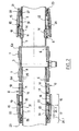
- the invention as it will now be described is more particularly suited to the connection of two lines 1, 2 to each other via a tubular body generally designated 3 forming a union in which an end portion 4, 5 of each pipe 1, 2 is engaged. It is obvious that the invention is also applicable to connection from a pipe to a functional organ, such as a filter, regulator, valve, distributor, tubular body then being an end piece integral with the organ.
- a functional organ such as a filter, regulator, valve, distributor, tubular body then being an end piece integral with the organ.
- the tubular body 3 forming the union has two opposite ends 6 by which the end portions 4, 5 of the pipes 1, 2 are introduced. Each end 6 of the tubular body 3 has an external thread 7.
- the tubular body 3 further comprises a side purge orifice closed by a plug.
- the tubular body 3 could by example understand instead of the bleed hole a transverse stitching duct to form a bypass.
- the connection device also comprises a stop ring generally designated at 8 formed of two half-rings 9 joined by an elastic ring 10.
- the half-rings 9 are made of metal or of a rigid thermoplastic material.
- the elastic ring 10 is made of elastomer and is received in a peripheral groove 11 formed on the external surface 12 of each half-ring 9 so that the elastic ring 10 slightly protrudes from the external surface 12.
- Each half-ring 9 has an internal surface 13 projecting from which extends a stud 14.
- the stop ring 8 has an internal diameter at the level of the internal surface 13 substantially equal to or slightly less than the corresponding outer diameter d of the 1,2 line. Since the ring 10 is elastic, the studs 14 can be separated from one another in order to be able to slide the ring 7 over the pipe 1, 2.
- connection device further comprises, for each end 6 of the tubular body 3, a sleeve generally designated as 15 divided into two parts axially 16 and 17, having means to ensure their waterproof and removable connection respectively with one end 6 of the tubular body 3 and with the pipe corresponding received in the tubular body 3.
- Part 16 of each sleeve 15 thus comprises side of its free end a thread 18 intended for cooperate with the thread 7 of the tubular body 3 and a groove 19 adjacent to part 17 to receive a seal O-ring 20 extending slightly protruding out of the throat 19.
- Part 17 of each sleeve 15 has one end free 21 delimiting an opening of diameter substantially equal to the external diameter of the pipe and a housing 22 of diameter greater than that of the opening connecting to it by a shoulder 23 and extending opposite to throat 19.
- the housing 22 slidably receives a piston 24 comprising on the end 21 side a section 24.1 having an internal diameter substantially equal to the diameter external of the pipeline and a section 24.2 defining a chamber, axially open, which is limited by the side of section 24.1 by a radial face 25 turned towards the ring 8 and which has an internal diameter substantially equal to the external diameter of the stop ring 8 when it is fitted to the pipeline.
- the free end 26 of section 24.1 has a conical interior shape widening in a direction opposite to section 24.2. This free end 26 defines with the shoulder 23 of the sleeve 15 an annular housing of variable volume.
- An annular sealing element 27 made of elastomer is arranged in the variable volume housing.
- the element sealing ring 27 is elastically deformable and has at rest a substantially equal internal diameter or slightly greater than the external diameter of the pipe and has a beveled end 28 extending on the side of the free end 26 of the piston 24.
- a sleeve 15 (fitted with the piston 24 and seals 20 and 27) and a stop ring 8 are successively strung on the end portion 4, 5 of the line 1, 2 corresponding in such a way that the studs 14 are received in housings 29 provided in the wall of line 1,2 in the vicinity of its end.
- the dwellings in question are here holes transverse but can also be recesses.
- the end portions 4.5 of the pipes 1.2 are then successively introduced into the tubular body 3 until the stop rings 8 come resting against the ends 6 thereof.
- the sleeves 15 are then brought to the ends 6 of the tubular body 3 and the parts 16 thereof are screwed on the threads 7.
- the stop rings 8 are then received in the chambers of sections 24.2 of pistons 24.
- each sleeve 15 During the screwing of each sleeve 15 on the tubular body 3, the free end 30 of the section 24.2 of the piston 24 of each sleeve 15 abuts against the corresponding end 6 of the tubular body 3 and / or the radial face 25 of the recess of the piston comes into stop against the stop ring 8 thus causing the sliding of the piston 24 in the housing 22 which comes to compress the annular sealing element 27 and apply this against the outer surface of the pipeline corresponding by the cooperation of external surfaces and internal conical ends 28 and 26 thereof.
- connection is sealed by the seal 20 bearing on a surface 6a of the end 6 of the tubular body 3 located in front of the thread 7, by the elastic ring 10 pressed against the internal cylindrical surface 31 the recess of the section 24.2 of the piston 24, and by the annular sealing element 27 compressed between the end free 26 of section 24.1 of piston 24, the shoulder 23 of sleeve 15 and the external surface of the pipe corresponding.
- Disconnection of lines 1 and 2 is carried out by unscrewing the sleeves 15 mounted on the tubular body 3 in which the ends 4 and 5 of the pipes are inserted. Note that, if the circuit is still under pressure, a leak occurs at the annular sealing element 27 from the start of unscrewing of the sleeve 15 thus alerting the operator.
- the stop ring 8 mounted on the end 4 of the pipe 1 is distant of the corresponding tubular body 3 by spreading the half-rings 9 to release the studs 14 from the housings 29 and sliding these along the pipeline corresponding.
- the tubular body 3 can then be moved along line 1 sufficiently to clear the end 5 of the pipe 2.
- Figure 2 illustrates this disconnection state which can be done in the same way at the other end of line 2, which allows lateral withdrawal line 2 of the circuit. Note that if the pipeline has sufficient flexibility, disconnection from its other end can be achieved by the unique unscrewing of the sleeve which connects it to the body corresponding, the bending allowing its extraction axial of this body.
- seal 20 provides the holding the piston 24 in the housing 22 when the sleeve 15 is disassembled.
- the sleeve may have a one-piece design without piston 24.
- the stop ring 8 can include any means adapted to allow its axial blocking on the pipe removably instead of crampons (for example a clamping means).
- the stop ring 8 can also be made in one piece comprising elastically deformable portions, or crampons retractable.
- the elastic ring 10 is optional, the half-rings being able to be maintained only by the surface internal of the housing formed in the sleeve.
Abstract
Description
La présente invention concerne des moyens de connexion d'une canalisation à un corps tubulaire. De tels moyens de connexion sont par exemple destinés à être utilisés dans des circuits de fluide sous pression pour raccorder deux éléments du circuit entre eux, tel que des canalisations, le corps tubulaire pouvant être un raccord entre deux canalisations ou un embout de raccordement d'une canalisation à un organe fonctionnel dont il est solidaire.The present invention relates to means for connection of a pipe to a tubular body. Of such connection means are for example intended to be used in pressurized fluid circuits for connect two elements of the circuit together, such as pipes, the tubular body possibly being a fitting between two pipes or a connection piece from a pipeline to a functional organ of which it is united.
On connaít des dispositifs de raccordement de deux canalisations comportant une union formée d'un corps tubulaire ayant deux extrémités par lesquelles une extrémité de chaque canalisation est destinée à être introduite dans l'union. Le dispositif de raccordement comprend également deux manchons vissés chacun sur une extrémité du corps tubulaire pour déformer, entre un épaulement interne du manchon et l'extrémité du corps tubulaire, une rondelle à griffes d'un état de repos dans lequel la rondelle à griffes est conique et a un diamètre interne supérieur au diamètre externe de la canalisation vers un état de déformation dans lequel la rondelle à griffes est aplatie et a un diamètre interne inférieur au diamètre externe de la canalisation de manière à mordre la surface externe de celle-ci. Le positionnement axial des canalisations dans le corps tubulaire est généralement assuré par l'intermédiaire d'épaulements annulaires agencés dans le corps tubulaire pour former des butées à l'enfoncement des canalisations dans l'union. Lorsque deux canalisations d'un circuit sont reliées l'une à l'autre et aux autres éléments du circuit par de tels dispositifs de raccordement, le retrait d'une des canalisations, par exemple pour la remplacer, nécessite, après le retrait des manchons, de pouvoir écarter l'un de l'autre les deux dispositifs de raccordement afin d'extraire les extrémités de la canalisation hors des corps tubulaires de ces dispositifs. Un tel démontage est difficilement réalisable dans un circuit relativement complexe dont certains éléments peuvent en outre être fixés sur des supports.We know connecting devices two pipes comprising a union formed by a body tubular having two ends through which one end of each pipe is intended to be introduced in union. The connection device comprises also two sleeves screwed each on one end tubular body to deform, between a shoulder internal of the sleeve and the end of the tubular body, a claw washer of a resting state in which the claw washer is conical and has a diameter internal greater than the external diameter of the pipe towards a deformation state in which the washer claws is flattened and has an internal diameter less than outer diameter of the pipe so as to bite the outer surface thereof. Axial positioning pipes in the tubular body is usually ensured via annular shoulders arranged in the tubular body to form stops for the sinking of the pipes into the union. When two pipes of a circuit are connected one to each other and to other elements of the circuit by such connection devices, removal of one of the pipes, for example to replace it, requires, after the removal of the sleeves, to be able to separate from one another the two connection devices in order to extract the ends of the pipe outside the tubular bodies of these devices. Such disassembly is hardly achievable in a relatively complex circuit some elements of which can also be attached to supports.
L'invention propose des moyens de connexion d'un nouveau type fournissant une alternative simple aux moyens existants et permettant lors d'une implantation dans un circuit de dégager latéralement un élément relié au circuit.The invention provides means for connecting a new type providing a simple alternative to existing means and allowing during implantation in a circuit to release laterally a connected element to the circuit.
A cet effet, on prévoit, selon l'invention, des moyens de connexion d'une canalisation à un corps tubulaire ayant une extrémité agencée pour recevoir une extrémité de la canalisation, les moyens de connexion comprenant un manchon divisé en des première et deuxième parties axialement successives pourvues de moyens pour assurer la liaison étanche et démontable de ces parties respectivement à l'extrémité du corps tubulaire et à la canalisation, et une bague amovible de butée pourvue de moyens de son blocage axial sur la canalisation en retrait de l'extrémité de celle-ci pour constituer un épaulement de butée à l'enfoncement de la canalisation dans le corps tubulaire et un épaulement de butée axiale entre la deuxième partie du manchon et la canalisation.To this end, according to the invention, provision is made for means for connecting a pipe to a tubular body having one end arranged to receive one end of the pipeline, the connection means comprising a sleeve divided into first and second axially successive parts provided with means for ensure the tight and removable connection of these parts respectively at the end of the tubular body and at the pipe, and a removable stop ring provided with means of its axial locking on the recessed pipeline from the end of it to form a shoulder of abutment in driving the pipe into the tubular body and an axial abutment shoulder between the second part of the sleeve and the pipe.
Grâce à cette disposition de bague de butée amovible, les démontages de canalisations ou d'organes dans un circuit de fluide sous pression sont devenus plus commodes. En effet, il suffit de désolidariser un ou les manchons du ou des corps tubulaires correspondants pour découvrir les bagues de butée et ainsi y accéder pour les débloquer des canalisations sur lesquelles elles sont implantées. Il n'existe plus alors d'obstacles au coulissement relatif de tous les composants de la liaison, ce qui permet de disposer d'une plus grande liberté de manoeuvre relative de ces composants pour leur emboítement et déboítement.Thanks to this removable stop ring arrangement, dismantling of pipes or components in a pressurized fluid circuit have become more convenient. Indeed, it suffices to separate one or more sleeves of the corresponding tubular body or bodies to discover the stop rings and thus access them for unlock the pipes on which they are installed. There are no longer any obstacles to sliding relative of all the components of the link, which provides greater freedom of maneuver relative of these components for their nesting and dislocation.
Selon un mode de réalisation particulier, la bague de butée est radialement expansible et a une surface interne en saillie de laquelle s'étend au moins un crampon de son blocage axial sur la canalisation, le crampon étant destiné à être reçu dans un logement ménagé de façon correspondante dans la paroi de la canalisation. Le blocage axial de la bague de butée sur le tube est réalisé aisément et peut être aussi aisément rompu.According to a particular embodiment, the ring stopper is radially expandable and has an internal surface projecting from which extends at least one spike its axial locking on the pipe, the crampon being intended to be received in a housing so arranged corresponding in the wall of the pipeline. The axial locking of the stop ring on the tube is achieved easily and can also be easily broken.
De préférence, la bague de butée comprend deux demi-bagues réunies par un anneau élastique reçu dans une gorge périphérique des demi-bagues. Les deux demi-bagues peuvent de la sorte être écartées l'une de l'autre de façon élastique permettant ainsi la mise en place de la bague de butée sur la canalisation et le déplacement de la bague de butée en dégageant le crampon hors du logement.Preferably, the stop ring comprises two half-rings joined by an elastic ring received in a peripheral groove of the half-rings. The two half rings can thus be separated from each other so elastic allowing the positioning of the ring of stop on the pipe and the displacement of the stop ring by releasing the crampon out of the housing.
D'autres caractéristiques et avantages de l'invention ressortiront à la lecture de la description qui suit d'un mode de réalisation particulier non limitatif de l'invention.Other features and benefits of the invention will emerge on reading the description which follows of a particular nonlimiting embodiment of the invention.
Il sera fait référence aux dessins annexés, parmi lesquels :
- la figure 1 est une vue en coupe longitudinale du raccordement de deux canalisations par un dispositif de connexion conforme à l'invention,
- la figure 2 est une vue analogue à la figure 1 de ce dispositif de connexion au cours de la déconnexion d'une des deux canalisations,
- la figure 3 est une vue en perspective d'une bague de butée d'un dispositif de connexion conforme à l'invention.
- FIG. 1 is a view in longitudinal section of the connection of two pipes by a connection device according to the invention,
- FIG. 2 is a view similar to FIG. 1 of this connection device during the disconnection of one of the two pipes,
- Figure 3 is a perspective view of a stop ring of a connection device according to the invention.
L'invention telle qu'elle va maintenant être décrite
est plus particulièrement adaptée au raccordement de deux
canalisations 1, 2 l'une à l'autre par l'intermédiaire
d'un corps tubulaire généralement désigné en 3 formant
une union dans lequel une portion d'extrémité 4, 5 de
chaque canalisation 1, 2 est engagée. Il va de soi que
l'invention est également applicable au raccordement
d'une canalisation à un organe fonctionnel, tel qu'un
filtre, un détendeur, une vanne, un distributeur, le
corps tubulaire étant alors un embout solidaire de l'organe.The invention as it will now be described
is more particularly suited to the connection of two
En référence aux figures, le corps tubulaire 3 formant
l'union posséde deux extrémités opposées 6 par lesquelles
les portions d'extrémité 4, 5 des canalisations
1, 2 y sont introduites. Chaque extrémité 6 du corps tubulaire
3 comporte un filetage externe 7. Le corps tubulaire
3 comprend en outre un orifice latéral de purge obturé
par un bouchon. Le corps tubulaire 3 pourrait par
exemple comprendre au lieu de l'orifice de purge un
conduit transversal de piquage pour former une dérivation.With reference to the figures, the
Le dispositif de connexion selon l'invention comprend
également une bague de butée généralement désignée
en 8 formée de deux demi-bagues 9 réunies par un anneau
élastique 10. Les demi-bagues 9 sont réalisées en métal
ou en un matériau thermoplastique rigide. L'anneau élastique
10 est réalisé en élastomère et est reçu dans une
gorge périphérique 11 ménagée sur la surface externe 12
de chaque demi-bague 9 de manière que l'anneau élastique
10 s'étende légèrement en saillie de la surface externe
12. Chaque demi-bague 9 a une surface interne 13 en saillie
de laquelle s'étend un crampon 14. Lorsque l'anneau
élastique 10 est dans un état de repos, la bague de butée
8 a un diamètre interne au niveau de la surface interne
13 sensiblement égal au diamètre externe d de la canalisation
1,2 correspondante ou légèrement inférieur à celui-ci.
Puisque l'anneau 10 est élastique on peut écarter
les crampons 14 l'un de l'autre pour pouvoir glisser la
bague 7 par dessus la canalisation 1, 2.The connection device according to the invention also comprises a stop ring generally designated at 8 formed of two half-
Le dispositif de connexion comprend en outre, pour
chaque extrémité 6 du corps tubulaire 3, un manchon généralement
désigné en 15 divisé en deux parties axialement
successives 16 et 17, ayant des moyens pour assurer leur
liaison étanche et démontable respectivement avec une extrémité
6 du corps tubulaire 3 et avec la canalisation
correspondante reçue dans le corps tubulaire 3.The connection device further comprises, for
each
La partie 16 de chaque manchon 15 comporte ainsi du
côté de son extrémité libre un taraudage 18 destiné à
coopérer avec le filetage 7 du corps tubulaire 3 et une
gorge 19 adjacente à la partie 17 pour recevoir un joint
torique 20 s'étendant légèrement en saillie hors de la
gorge 19.
La partie 17 de chaque manchon 15 comprend une extrémité
libre 21 délimitant une ouverture de diamètre
sensiblement égal au diamètre externe de la canalisation
et un logement 22 de diamètre supérieur à celui de l'ouverture
se raccordant à celle-ci par un épaulement 23 et
s'étendant à l'opposé jusqu'à la gorge 19.
Le logement 22 reçoit à coulissement un piston 24
comportant du côté de l'extrémité 21 une section 24.1
ayant un diamètre interne sensiblement égal au diamètre
externe de la canalisation et une section 24.2 définissant
un chambrage, ouvert axialement, qui est limité du
côté de la section 24.1 par une face radiale 25 tournée
en direction de la bague 8 et qui a un diamètre interne
sensiblement égal au diamètre externe de la bague de butée
8 lorsqu'elle équipe la canalisation. L'extrémité libre
26 de la section 24.1 a une forme intérieure conique
s'évasant dans une direction opposée à la section 24.2.
Cette extrémité libre 26 définit avec l'épaulemenc 23 du
manchon 15 un logement annulaire de volume variable.The
Un élément annulaire d'étanchéité 27 en élastomère
est disposé dans le logement de volume variable. L'élément
annulaire d'étanchéité 27 est élastiquement déformable
et a au repos un diamètre interne sensiblement égal
ou légèrement supérieur au diamètre externe de la canalisation
et possède une extrémité biseautée 28 s'étendant
du côté de l'extrémité libre 26 du piston 24.An
Préalablement au raccordement des deux tronçons de
canalisation 1, 2, un manchon 15 (équipé du piston 24 et
des joints 20 et 27) et une bague de butée 8 sont successivement
enfilés sur la portion d'extrémité 4, 5 de la
canalisation 1, 2 correspondante de telle manière que les
crampons 14 soient reçus dans des logements 29 ménagés
dans la paroi de la canalisation 1,2 au voisinage de son
extrémité. Les logements en question sont ici des perçages
transversaux mais peuvent être également des renfoncements.Before connecting the two sections of
Les portions d'extrémité 4,5 des canalisations 1,2
sont ensuite introduites successivement dans le corps tubulaire
3 jusqu'à ce que les bagues de butée 8 viennent
en appui contre les extrémités 6 de celui-ci. Les manchons
15 sont ensuite ramenés sur les extrémités 6 du
corps tubulaire 3 et les parties 16 de ceux-ci sont vissées
sur les filetages 7. Les bagues de butée 8 sont
alors reçues dans les chambrages des sections 24.2 des
pistons 24.The end portions 4.5 of the pipes 1.2
are then successively introduced into the
Au cours du vissage de chaque manchon 15 sur le
corps tubulaire 3, l'extrémité libre 30 de la section
24.2 du piston 24 de chaque manchon 15 vient en butée
contre l'extrémité 6 correspondante du corps tubulaire 3
et/ou la face radiale 25 du chambrage du piston vient en
butée contre la bague de butée 8 provoquant ainsi le coulissement
du piston 24 dans le logement 22 qui vient comprimer
l'élément annulaire d'étanchéité 27 et appliquer
celui-ci contre la surface externe de la canalisation
correspondante par la coopération des surfaces externe et
interne coniques des extrémités 28 et 26 de ceux-ci.
L'étanchéité du raccordement est assurée par le joint 20
portant sur une portée 6a de l'extrémité 6 du corps tubulaire
3 située en avant du filetage 7, par l'anneau élastique
10 pressé contre la surface cylindrique interne 31
du chambrage de la section 24.2 du piston 24, et par
l'élément annulaire d'étanchéité 27 comprimé entre l'extrémité
libre 26 de la section 24.1 du piston 24, l'épaulement
23 du manchon 15 et la surface externe de la canalisation
correspondante.During the screwing of each
La déconnexion des canalisations 1 et 2 est réalisée
en dévissant les manchons 15 montés sur le corps tubulaire
3 dans lequel les extrémités 4 et 5 des canalisations
sont insérées. On remarquera que, si le circuit est
toujours sous pression, une fuite se produit au niveau de
l'élément annulaire d'étanchéité 27 dès le début du dévissage
du manchon 15 alertant ainsi l'opérateur.Disconnection of
Une fois ces manchons 15 dévissés, la bague de butée
8 montée sur l'extrémité 4 de la canalisation 1 est éloignée
du corps tubulaire 3 correspondant en écartant les
demi-bagues 9 pour dégager les crampons 14 des logements
29 et en faisant coulisser celles-ci le long de la canalisation
correspondante. Le corps tubulaire 3 peut alors
être déplacé le long de la canalisation 1 de façon suffisante
pour dégager l'extrémité 5 de la canalisation 2.Once these
La figure 2 illustre cet état de déconnexion qui
peut être réalisé de la même manière à l'autre extrémité
de la canalisation 2, ce qui permet de retirer latéralement
la canalisation 2 du circuit. On notera que si la
canalisation possède une flexibilité suffisante, la déconnexion
de son autre extrémité peut être réalisée par
le dévissage unique du manchon qui la raccorde au corps
correspondant, la flexion permettant son extraction
axiale de ce corps.Figure 2 illustrates this disconnection state which
can be done in the same way at the other end
of
On remarquera que lorsque le circuit est sous pression
au moment du dévissage des manchons 15, le corps tubulaire
3 est maintenu en position sur les extrémités de
canalisation par l'intermédiaire des bagues de butée 8
évitant ainsi un déplacement brutal incontrôlé donc dangereux
des composants de la connexion.Note that when the circuit is under pressure
when the
On notera par ailleurs que le joint 20 assure le
maintien du piston 24 dans le logement 22 lorsque le manchon
15 est démonté.Note also that the
Bien entendu l'invention n'est pas limitée au mode de réalisation décrit et on peut y apporter des variantes de réalisation sans sortir du cadre de l'invention tel que défini par les revendications.Of course, the invention is not limited to the mode described and we can make variants without departing from the scope of the invention as as defined by the claims.
En particulier, ce n'est pas sortir du cadre de
l'invention que de prévoir à la place d'une liaison filetée
entre le manchon 15 et le corps tubulaire 3 une autre
liaison par exemple par emmanchement qui serait maintenu
au moyen d'un bridage extérieur entre la bague de butée 8
et une collerette que comporterait en correspondance
l'extrémité 6 du corps tubulaire 3.In particular, this is not going beyond the ambit of
the invention to provide instead of a threaded connection
between the
En outre, le manchon peut avoir une conception monobloc
sans piston 24.In addition, the sleeve may have a one-piece design
without
Enfin, la bague de butée 8 peut comprendre tout
moyen adapté pour permettre son blocage axial sur la canalisation
de façon amovible aux lieu et place des crampons
(par exemple un moyen de serrage). La bague de butée
8 peut en outre être réalisée en une seule pièce comprenant
des portions élastiquement déformables, ou des crampons
escamotables.Finally, the
Par ailleurs, l'anneau élastique 10 est facultatif,
les demi-bagues pouvant n'être maintenues que par la surface
interne du logement ménagé dans le manchon.Furthermore, the
Claims (7)
Applications Claiming Priority (2)
| Application Number | Priority Date | Filing Date | Title |
|---|---|---|---|
| FR9911738A FR2798717B1 (en) | 1999-09-20 | 1999-09-20 | MEANS FOR CONNECTING A PIPING TO A TUBULAR BODY |
| FR9911738 | 1999-09-20 |
Publications (2)
| Publication Number | Publication Date |
|---|---|
| EP1085245A1 true EP1085245A1 (en) | 2001-03-21 |
| EP1085245B1 EP1085245B1 (en) | 2005-02-09 |
Family
ID=9550043
Family Applications (1)
| Application Number | Title | Priority Date | Filing Date |
|---|---|---|---|
| EP00402509A Expired - Lifetime EP1085245B1 (en) | 1999-09-20 | 2000-09-12 | Means for connecting a pipe to a tubular body |
Country Status (9)
| Country | Link |
|---|---|
| US (1) | US6508493B1 (en) |
| EP (1) | EP1085245B1 (en) |
| JP (1) | JP3426575B2 (en) |
| AT (1) | ATE289033T1 (en) |
| AU (1) | AU751547B2 (en) |
| CA (1) | CA2319925A1 (en) |
| DE (1) | DE60017999T2 (en) |
| FR (1) | FR2798717B1 (en) |
| TW (1) | TW459114B (en) |
Cited By (5)
| Publication number | Priority date | Publication date | Assignee | Title |
|---|---|---|---|---|
| FR2918150A1 (en) * | 2007-06-29 | 2009-01-02 | Legris Sa | OUTDOOR WASHING CONNECTION EASY |
| ITTO20080747A1 (en) * | 2008-10-10 | 2010-04-11 | Sicomat S R L | FLUID SEALED JUNCTION FOR THE CREATION OF A PRESSURE FLUID POWER SUPPLY CIRCUIT |
| FR2997163A1 (en) * | 2014-02-06 | 2014-04-25 | Parker Hannifin Mfg France Sas | Locking ring for use in connection unit to connect pipe to tubular body, has rigid sectors articulated with respect to each other by elastically deformable annular portion, where sectors and portion are formed from single piece |
| CN103968164A (en) * | 2014-05-23 | 2014-08-06 | 苏州博讯仪器有限公司 | Pipeline connecting device |
| EP2789417A1 (en) | 2013-04-12 | 2014-10-15 | Parker Hannifin Manufacturing France SAS | Drilling jig for tubes of different diameters |
Families Citing this family (11)
| Publication number | Priority date | Publication date | Assignee | Title |
|---|---|---|---|---|
| AU763565B2 (en) * | 1999-07-02 | 2003-07-24 | Vinidex Pty Limited | Pipe deflection coupling |
| US6874970B2 (en) * | 2002-10-10 | 2005-04-05 | Playcore, Inc. | Coupling assembly having a split-ring collar locking mechanism |
| FR2860853A1 (en) * | 2003-10-10 | 2005-04-15 | Legris Sa | DEVICE FOR CONNECTING A THREADED TUBULAR NOSE TUBE WITH SEAL |
| US20050110270A1 (en) * | 2003-11-20 | 2005-05-26 | I-Jen Huang | Piping connector |
| GB2468999B (en) | 2008-01-22 | 2012-08-08 | Cameron Int Corp | Connection methods and systems |
| KR101573258B1 (en) * | 2015-04-28 | 2015-12-02 | 주식회사 유니락 | Method of manufacturing a stop collar for pipe fitting device and the stop collar |
| EP3320247A1 (en) * | 2015-08-26 | 2018-05-16 | Swagelok Company | Conduit retaining structure for conduit fitting |
| US20170227151A1 (en) | 2016-02-04 | 2017-08-10 | Swagelok Company | Component retaining structure for conduit fitting |
| CN107044573B (en) * | 2017-02-09 | 2022-10-14 | 广东福斯特流体技术有限公司 | Quick pipeline connector easy to disassemble and assemble |
| CN113374053A (en) * | 2021-06-17 | 2021-09-10 | 中国水利水电科学研究院 | Energy-saving type anti-seepage mechanism of ground sewer pipe for water pollution control |
| CN113719125A (en) * | 2021-08-12 | 2021-11-30 | 赵东 | Concrete placement high frequency vibrates integration assembled pipeline discharge head |
Citations (5)
| Publication number | Priority date | Publication date | Assignee | Title |
|---|---|---|---|---|
| US1675808A (en) * | 1927-02-05 | 1928-07-03 | Charles J Kliss | Pipe joint |
| US1703696A (en) * | 1925-04-07 | 1929-02-26 | Stratford Charles Walcott | Method of and coupling for joining pipes or the like |
| FR1334545A (en) * | 1962-06-29 | 1963-08-09 | Rech S Tech Et Ind Soc D | Quick-fit fitting |
| EP0545469A1 (en) * | 1991-12-04 | 1993-06-09 | Pierre André Weinberg | Procedure and freely adjustable device of a nipple in a corresponding female element |
| US5348351A (en) * | 1990-12-18 | 1994-09-20 | Lafleur Petroleum Services, Inc. | Coupling apparatus |
Family Cites Families (2)
| Publication number | Priority date | Publication date | Assignee | Title |
|---|---|---|---|---|
| US2758852A (en) * | 1953-01-16 | 1956-08-14 | Dresser Ind | Coupling for threadless pipe with independent sealing and gripping means |
| US5120092A (en) * | 1990-08-06 | 1992-06-09 | Tibor Gorog | Apparatus to provide a threaded coupling for a broken pipe |
-
1999
- 1999-09-20 FR FR9911738A patent/FR2798717B1/en not_active Expired - Fee Related
-
2000
- 2000-09-12 DE DE60017999T patent/DE60017999T2/en not_active Expired - Lifetime
- 2000-09-12 EP EP00402509A patent/EP1085245B1/en not_active Expired - Lifetime
- 2000-09-12 AT AT00402509T patent/ATE289033T1/en not_active IP Right Cessation
- 2000-09-14 CA CA002319925A patent/CA2319925A1/en not_active Abandoned
- 2000-09-16 TW TW089119043A patent/TW459114B/en not_active IP Right Cessation
- 2000-09-19 AU AU59494/00A patent/AU751547B2/en not_active Ceased
- 2000-09-20 US US09/666,601 patent/US6508493B1/en not_active Expired - Lifetime
- 2000-09-20 JP JP2000285422A patent/JP3426575B2/en not_active Expired - Fee Related
Patent Citations (5)
| Publication number | Priority date | Publication date | Assignee | Title |
|---|---|---|---|---|
| US1703696A (en) * | 1925-04-07 | 1929-02-26 | Stratford Charles Walcott | Method of and coupling for joining pipes or the like |
| US1675808A (en) * | 1927-02-05 | 1928-07-03 | Charles J Kliss | Pipe joint |
| FR1334545A (en) * | 1962-06-29 | 1963-08-09 | Rech S Tech Et Ind Soc D | Quick-fit fitting |
| US5348351A (en) * | 1990-12-18 | 1994-09-20 | Lafleur Petroleum Services, Inc. | Coupling apparatus |
| EP0545469A1 (en) * | 1991-12-04 | 1993-06-09 | Pierre André Weinberg | Procedure and freely adjustable device of a nipple in a corresponding female element |
Cited By (9)
| Publication number | Priority date | Publication date | Assignee | Title |
|---|---|---|---|---|
| FR2918150A1 (en) * | 2007-06-29 | 2009-01-02 | Legris Sa | OUTDOOR WASHING CONNECTION EASY |
| WO2009016287A2 (en) * | 2007-06-29 | 2009-02-05 | Legris Sa | Connector with improved outer washing |
| WO2009016287A3 (en) * | 2007-06-29 | 2009-05-22 | Legris Sa | Connector with improved outer washing |
| ITTO20080747A1 (en) * | 2008-10-10 | 2010-04-11 | Sicomat S R L | FLUID SEALED JUNCTION FOR THE CREATION OF A PRESSURE FLUID POWER SUPPLY CIRCUIT |
| EP2789417A1 (en) | 2013-04-12 | 2014-10-15 | Parker Hannifin Manufacturing France SAS | Drilling jig for tubes of different diameters |
| FR2997163A1 (en) * | 2014-02-06 | 2014-04-25 | Parker Hannifin Mfg France Sas | Locking ring for use in connection unit to connect pipe to tubular body, has rigid sectors articulated with respect to each other by elastically deformable annular portion, where sectors and portion are formed from single piece |
| WO2015117874A1 (en) | 2014-02-06 | 2015-08-13 | Parker Hannifin Manufacturing France Sas | Ring for fastening a pipe to a tubular body and connection means comprising such a ring |
| US9822909B2 (en) | 2014-02-06 | 2017-11-21 | Parker Hannifin Manufacturing France Sas | Ring for fastening a pipe to a tubular body and connection means comprising such a ring |
| CN103968164A (en) * | 2014-05-23 | 2014-08-06 | 苏州博讯仪器有限公司 | Pipeline connecting device |
Also Published As
| Publication number | Publication date |
|---|---|
| DE60017999D1 (en) | 2005-03-17 |
| AU5949400A (en) | 2001-03-22 |
| JP3426575B2 (en) | 2003-07-14 |
| AU751547B2 (en) | 2002-08-22 |
| US6508493B1 (en) | 2003-01-21 |
| FR2798717B1 (en) | 2001-10-19 |
| JP2001124257A (en) | 2001-05-11 |
| DE60017999T2 (en) | 2006-01-05 |
| ATE289033T1 (en) | 2005-02-15 |
| FR2798717A1 (en) | 2001-03-23 |
| TW459114B (en) | 2001-10-11 |
| EP1085245B1 (en) | 2005-02-09 |
| CA2319925A1 (en) | 2001-03-20 |
Similar Documents
| Publication | Publication Date | Title |
|---|---|---|
| EP1085245B1 (en) | Means for connecting a pipe to a tubular body | |
| EP0960300B1 (en) | Device for fast connection of a tube to a rigid element with anti-extraction ring and safety seal | |
| FR2493467A1 (en) | QUICK COUPLING HYDRAULIC CONNECTION DEVICE | |
| EP0857274B1 (en) | Device for connecting a tube to a coupling | |
| WO1996017201A1 (en) | Quick coupling device between a tube and a rigid nozzle | |
| EP1369632B1 (en) | Means for the connection of two pipes | |
| FR2487945A1 (en) | SEALING PRESS OR SEAL, IN SCRATCHED ELEMENTS THAT MAY BE PLACED LATERALLY, IN PARTICULAR ON A TUBE | |
| FR2931534A1 (en) | QUICK CONNECT DEVICE FOR HIGH PRESSURES. | |
| FR2810087A1 (en) | Insert for implanting pipe connection in tapped housing comprises body which fits against tapped section, on which rings with anchor lugs are mounted, each lug being compressible from position above outer surface of insert to below it | |
| FR2901340A1 (en) | HYDRAULIC DISPENSER ARRANGEMENT IN THE FORM OF A CARTRIDGE | |
| EP0300023A1 (en) | Rapid assembly connector. | |
| FR2591309A1 (en) | Hydraulic connector with rapid manual connection for a fluid pipeline | |
| EP1625322B1 (en) | Quick-connect coupling for hydraulic fluid conduits | |
| EP0197874B1 (en) | Elastic hook element for instantaneous fluid conduits-coupling systems | |
| EP1538383A1 (en) | Compression fitting for multilayered tubes | |
| FR2492499A1 (en) | CONNECTING DEVICE FOR TUBES | |
| FR2790056A1 (en) | Pipe coupling has inner deformable claws and seal ring with toroid, cylindrical and conical surfaces | |
| FR2788581A1 (en) | CONDUIT END CONNECTION ASSEMBLY TO AN ELEMENT | |
| FR2938625A1 (en) | CONNECTING DEVICE HAVING REVERSE SEALING AND HITCHING ZONES. | |
| FR2520478A1 (en) | SELF-CLOSING COUPLER, PARTICULARLY FOR FLUID OR REFRIGERANT | |
| FR3098886A1 (en) | Cartridge-type fluid connection device | |
| EP2079956A2 (en) | Rotary connection device | |
| FR3070136B1 (en) | TOOLING ASSEMBLY OF TWO CONDUITS | |
| EP0013544A1 (en) | Threaded sleeve coupling having valves with an adjustable aperture | |
| FR3087517A1 (en) | CONNECTION DEVICE FOR REALIZING THE TUBING OF A TUBE ON A PIPE WALL |
Legal Events
| Date | Code | Title | Description |
|---|---|---|---|
| PUAI | Public reference made under article 153(3) epc to a published international application that has entered the european phase |
Free format text: ORIGINAL CODE: 0009012 |
|
| AK | Designated contracting states |
Kind code of ref document: A1 Designated state(s): AT BE CH CY DE DK ES FI FR GB GR IE IT LI LU MC NL PT SE |
|
| AX | Request for extension of the european patent |
Free format text: AL;LT;LV;MK;RO;SI |
|
| 17P | Request for examination filed |
Effective date: 20010705 |
|
| AKX | Designation fees paid |
Free format text: AT BE CH CY DE DK ES FI FR GB GR IE IT LI LU MC NL PT SE |
|
| 17Q | First examination report despatched |
Effective date: 20030307 |
|
| GRAP | Despatch of communication of intention to grant a patent |
Free format text: ORIGINAL CODE: EPIDOSNIGR1 |
|
| GRAS | Grant fee paid |
Free format text: ORIGINAL CODE: EPIDOSNIGR3 |
|
| GRAA | (expected) grant |
Free format text: ORIGINAL CODE: 0009210 |
|
| AK | Designated contracting states |
Kind code of ref document: B1 Designated state(s): AT BE CH CY DE DK ES FI FR GB GR IE IT LI LU MC NL PT SE |
|
| PG25 | Lapsed in a contracting state [announced via postgrant information from national office to epo] |
Ref country code: AT Free format text: LAPSE BECAUSE OF FAILURE TO SUBMIT A TRANSLATION OF THE DESCRIPTION OR TO PAY THE FEE WITHIN THE PRESCRIBED TIME-LIMIT Effective date: 20050209 Ref country code: NL Free format text: LAPSE BECAUSE OF FAILURE TO SUBMIT A TRANSLATION OF THE DESCRIPTION OR TO PAY THE FEE WITHIN THE PRESCRIBED TIME-LIMIT Effective date: 20050209 Ref country code: FI Free format text: LAPSE BECAUSE OF FAILURE TO SUBMIT A TRANSLATION OF THE DESCRIPTION OR TO PAY THE FEE WITHIN THE PRESCRIBED TIME-LIMIT Effective date: 20050209 Ref country code: IE Free format text: LAPSE BECAUSE OF FAILURE TO SUBMIT A TRANSLATION OF THE DESCRIPTION OR TO PAY THE FEE WITHIN THE PRESCRIBED TIME-LIMIT Effective date: 20050209 |
|
| REG | Reference to a national code |
Ref country code: GB Ref legal event code: FG4D Free format text: NOT ENGLISH |
|
| REG | Reference to a national code |
Ref country code: CH Ref legal event code: EP |
|
| REG | Reference to a national code |
Ref country code: IE Ref legal event code: FG4D Free format text: FRENCH |
|
| REF | Corresponds to: |
Ref document number: 60017999 Country of ref document: DE Date of ref document: 20050317 Kind code of ref document: P |
|
| GBT | Gb: translation of ep patent filed (gb section 77(6)(a)/1977) |
Effective date: 20050413 |
|
| PG25 | Lapsed in a contracting state [announced via postgrant information from national office to epo] |
Ref country code: DK Free format text: LAPSE BECAUSE OF FAILURE TO SUBMIT A TRANSLATION OF THE DESCRIPTION OR TO PAY THE FEE WITHIN THE PRESCRIBED TIME-LIMIT Effective date: 20050509 Ref country code: SE Free format text: LAPSE BECAUSE OF FAILURE TO SUBMIT A TRANSLATION OF THE DESCRIPTION OR TO PAY THE FEE WITHIN THE PRESCRIBED TIME-LIMIT Effective date: 20050509 Ref country code: GR Free format text: LAPSE BECAUSE OF FAILURE TO SUBMIT A TRANSLATION OF THE DESCRIPTION OR TO PAY THE FEE WITHIN THE PRESCRIBED TIME-LIMIT Effective date: 20050509 |
|
| PG25 | Lapsed in a contracting state [announced via postgrant information from national office to epo] |
Ref country code: ES Free format text: LAPSE BECAUSE OF FAILURE TO SUBMIT A TRANSLATION OF THE DESCRIPTION OR TO PAY THE FEE WITHIN THE PRESCRIBED TIME-LIMIT Effective date: 20050520 |
|
| NLV1 | Nl: lapsed or annulled due to failure to fulfill the requirements of art. 29p and 29m of the patents act | ||
| PG25 | Lapsed in a contracting state [announced via postgrant information from national office to epo] |
Ref country code: CY Free format text: LAPSE BECAUSE OF FAILURE TO SUBMIT A TRANSLATION OF THE DESCRIPTION OR TO PAY THE FEE WITHIN THE PRESCRIBED TIME-LIMIT Effective date: 20050912 |
|
| REG | Reference to a national code |
Ref country code: IE Ref legal event code: FD4D |
|
| PG25 | Lapsed in a contracting state [announced via postgrant information from national office to epo] |
Ref country code: LU Free format text: LAPSE BECAUSE OF NON-PAYMENT OF DUE FEES Effective date: 20050930 Ref country code: CH Free format text: LAPSE BECAUSE OF NON-PAYMENT OF DUE FEES Effective date: 20050930 Ref country code: BE Free format text: LAPSE BECAUSE OF NON-PAYMENT OF DUE FEES Effective date: 20050930 Ref country code: MC Free format text: LAPSE BECAUSE OF NON-PAYMENT OF DUE FEES Effective date: 20050930 Ref country code: LI Free format text: LAPSE BECAUSE OF NON-PAYMENT OF DUE FEES Effective date: 20050930 |
|
| PLBE | No opposition filed within time limit |
Free format text: ORIGINAL CODE: 0009261 |
|
| STAA | Information on the status of an ep patent application or granted ep patent |
Free format text: STATUS: NO OPPOSITION FILED WITHIN TIME LIMIT |
|
| 26N | No opposition filed |
Effective date: 20051110 |
|
| REG | Reference to a national code |
Ref country code: CH Ref legal event code: PL |
|
| BERE | Be: lapsed |
Owner name: LEGRIS S.A. Effective date: 20050930 |
|
| PG25 | Lapsed in a contracting state [announced via postgrant information from national office to epo] |
Ref country code: PT Free format text: LAPSE BECAUSE OF NON-PAYMENT OF DUE FEES Effective date: 20050709 |
|
| REG | Reference to a national code |
Ref country code: DE Ref legal event code: R082 Ref document number: 60017999 Country of ref document: DE Representative=s name: SCHAUMBURG & PARTNER PATENTANWAELTE GBR, DE Ref country code: DE Ref legal event code: R082 Ref document number: 60017999 Country of ref document: DE Representative=s name: SCHAUMBURG UND PARTNER PATENTANWAELTE MBB, DE |
|
| REG | Reference to a national code |
Ref country code: FR Ref legal event code: PLFP Year of fee payment: 17 |
|
| REG | Reference to a national code |
Ref country code: FR Ref legal event code: PLFP Year of fee payment: 18 |
|
| REG | Reference to a national code |
Ref country code: FR Ref legal event code: PLFP Year of fee payment: 19 |
|
| PGFP | Annual fee paid to national office [announced via postgrant information from national office to epo] |
Ref country code: IT Payment date: 20190916 Year of fee payment: 20 Ref country code: DE Payment date: 20190913 Year of fee payment: 20 Ref country code: FR Payment date: 20190930 Year of fee payment: 20 |
|
| PGFP | Annual fee paid to national office [announced via postgrant information from national office to epo] |
Ref country code: GB Payment date: 20190919 Year of fee payment: 20 |
|
| REG | Reference to a national code |
Ref country code: DE Ref legal event code: R071 Ref document number: 60017999 Country of ref document: DE |
|
| REG | Reference to a national code |
Ref country code: GB Ref legal event code: PE20 Expiry date: 20200911 |
|
| PG25 | Lapsed in a contracting state [announced via postgrant information from national office to epo] |
Ref country code: GB Free format text: LAPSE BECAUSE OF EXPIRATION OF PROTECTION Effective date: 20200911 |