EP0895846A1 - Verfahren und Form zum Herstellen eines bekleideten Kunststoffgegenstandes mit einer geschnittenen und entspannten Dekorfolie und hergestellter Gegenstand - Google Patents
Verfahren und Form zum Herstellen eines bekleideten Kunststoffgegenstandes mit einer geschnittenen und entspannten Dekorfolie und hergestellter Gegenstand Download PDFInfo
- Publication number
- EP0895846A1 EP0895846A1 EP98401812A EP98401812A EP0895846A1 EP 0895846 A1 EP0895846 A1 EP 0895846A1 EP 98401812 A EP98401812 A EP 98401812A EP 98401812 A EP98401812 A EP 98401812A EP 0895846 A1 EP0895846 A1 EP 0895846A1
- Authority
- EP
- European Patent Office
- Prior art keywords
- sheet
- mold
- zone
- cutting
- opening
- Prior art date
- Legal status (The legal status is an assumption and is not a legal conclusion. Google has not performed a legal analysis and makes no representation as to the accuracy of the status listed.)
- Granted
Links
Images


Classifications
-
- B—PERFORMING OPERATIONS; TRANSPORTING
- B29—WORKING OF PLASTICS; WORKING OF SUBSTANCES IN A PLASTIC STATE IN GENERAL
- B29C—SHAPING OR JOINING OF PLASTICS; SHAPING OF MATERIAL IN A PLASTIC STATE, NOT OTHERWISE PROVIDED FOR; AFTER-TREATMENT OF THE SHAPED PRODUCTS, e.g. REPAIRING
- B29C70/00—Shaping composites, i.e. plastics material comprising reinforcements, fillers or preformed parts, e.g. inserts
- B29C70/68—Shaping composites, i.e. plastics material comprising reinforcements, fillers or preformed parts, e.g. inserts by incorporating or moulding on preformed parts, e.g. inserts or layers, e.g. foam blocks
- B29C70/681—Component parts, details or accessories; Auxiliary operations
- B29C70/683—Pretreatment of the preformed part, e.g. insert
-
- B—PERFORMING OPERATIONS; TRANSPORTING
- B29—WORKING OF PLASTICS; WORKING OF SUBSTANCES IN A PLASTIC STATE IN GENERAL
- B29C—SHAPING OR JOINING OF PLASTICS; SHAPING OF MATERIAL IN A PLASTIC STATE, NOT OTHERWISE PROVIDED FOR; AFTER-TREATMENT OF THE SHAPED PRODUCTS, e.g. REPAIRING
- B29C43/00—Compression moulding, i.e. applying external pressure to flow the moulding material; Apparatus therefor
- B29C43/02—Compression moulding, i.e. applying external pressure to flow the moulding material; Apparatus therefor of articles of definite length, i.e. discrete articles
- B29C43/18—Compression moulding, i.e. applying external pressure to flow the moulding material; Apparatus therefor of articles of definite length, i.e. discrete articles incorporating preformed parts or layers, e.g. compression moulding around inserts or for coating articles
- B29C43/183—Compression moulding, i.e. applying external pressure to flow the moulding material; Apparatus therefor of articles of definite length, i.e. discrete articles incorporating preformed parts or layers, e.g. compression moulding around inserts or for coating articles the preformed layer being a lining, e.g. shaped in the mould before compression moulding, or a preformed shell adapted to the shape of the mould
- B29C43/184—Compression moulding, i.e. applying external pressure to flow the moulding material; Apparatus therefor of articles of definite length, i.e. discrete articles incorporating preformed parts or layers, e.g. compression moulding around inserts or for coating articles the preformed layer being a lining, e.g. shaped in the mould before compression moulding, or a preformed shell adapted to the shape of the mould shaped by the compression of the material during moulding
-
- B—PERFORMING OPERATIONS; TRANSPORTING
- B29—WORKING OF PLASTICS; WORKING OF SUBSTANCES IN A PLASTIC STATE IN GENERAL
- B29C—SHAPING OR JOINING OF PLASTICS; SHAPING OF MATERIAL IN A PLASTIC STATE, NOT OTHERWISE PROVIDED FOR; AFTER-TREATMENT OF THE SHAPED PRODUCTS, e.g. REPAIRING
- B29C43/00—Compression moulding, i.e. applying external pressure to flow the moulding material; Apparatus therefor
- B29C43/32—Component parts, details or accessories; Auxiliary operations
- B29C43/36—Moulds for making articles of definite length, i.e. discrete articles
- B29C43/40—Moulds for making articles of definite length, i.e. discrete articles with means for cutting the article
-
- B—PERFORMING OPERATIONS; TRANSPORTING
- B29—WORKING OF PLASTICS; WORKING OF SUBSTANCES IN A PLASTIC STATE IN GENERAL
- B29C—SHAPING OR JOINING OF PLASTICS; SHAPING OF MATERIAL IN A PLASTIC STATE, NOT OTHERWISE PROVIDED FOR; AFTER-TREATMENT OF THE SHAPED PRODUCTS, e.g. REPAIRING
- B29C45/00—Injection moulding, i.e. forcing the required volume of moulding material through a nozzle into a closed mould; Apparatus therefor
- B29C45/14—Injection moulding, i.e. forcing the required volume of moulding material through a nozzle into a closed mould; Apparatus therefor incorporating preformed parts or layers, e.g. injection moulding around inserts or for coating articles
- B29C45/1418—Injection moulding, i.e. forcing the required volume of moulding material through a nozzle into a closed mould; Apparatus therefor incorporating preformed parts or layers, e.g. injection moulding around inserts or for coating articles the inserts being deformed or preformed, e.g. by the injection pressure
- B29C45/14221—Injection moulding, i.e. forcing the required volume of moulding material through a nozzle into a closed mould; Apparatus therefor incorporating preformed parts or layers, e.g. injection moulding around inserts or for coating articles the inserts being deformed or preformed, e.g. by the injection pressure by tools, e.g. cutting means
-
- B—PERFORMING OPERATIONS; TRANSPORTING
- B29—WORKING OF PLASTICS; WORKING OF SUBSTANCES IN A PLASTIC STATE IN GENERAL
- B29C—SHAPING OR JOINING OF PLASTICS; SHAPING OF MATERIAL IN A PLASTIC STATE, NOT OTHERWISE PROVIDED FOR; AFTER-TREATMENT OF THE SHAPED PRODUCTS, e.g. REPAIRING
- B29C45/00—Injection moulding, i.e. forcing the required volume of moulding material through a nozzle into a closed mould; Apparatus therefor
- B29C45/14—Injection moulding, i.e. forcing the required volume of moulding material through a nozzle into a closed mould; Apparatus therefor incorporating preformed parts or layers, e.g. injection moulding around inserts or for coating articles
- B29C45/14336—Coating a portion of the article, e.g. the edge of the article
- B29C45/14344—Moulding in or through a hole in the article, e.g. outsert moulding
-
- B—PERFORMING OPERATIONS; TRANSPORTING
- B29—WORKING OF PLASTICS; WORKING OF SUBSTANCES IN A PLASTIC STATE IN GENERAL
- B29C—SHAPING OR JOINING OF PLASTICS; SHAPING OF MATERIAL IN A PLASTIC STATE, NOT OTHERWISE PROVIDED FOR; AFTER-TREATMENT OF THE SHAPED PRODUCTS, e.g. REPAIRING
- B29C70/00—Shaping composites, i.e. plastics material comprising reinforcements, fillers or preformed parts, e.g. inserts
- B29C70/68—Shaping composites, i.e. plastics material comprising reinforcements, fillers or preformed parts, e.g. inserts by incorporating or moulding on preformed parts, e.g. inserts or layers, e.g. foam blocks
- B29C70/74—Moulding material on a relatively small portion of the preformed part, e.g. outsert moulding
-
- B—PERFORMING OPERATIONS; TRANSPORTING
- B29—WORKING OF PLASTICS; WORKING OF SUBSTANCES IN A PLASTIC STATE IN GENERAL
- B29C—SHAPING OR JOINING OF PLASTICS; SHAPING OF MATERIAL IN A PLASTIC STATE, NOT OTHERWISE PROVIDED FOR; AFTER-TREATMENT OF THE SHAPED PRODUCTS, e.g. REPAIRING
- B29C2793/00—Shaping techniques involving a cutting or machining operation
- B29C2793/0081—Shaping techniques involving a cutting or machining operation before shaping
Definitions
- the invention relates to a method of dressing with at least one non-rigid decor sheet of part of one face of a support piece made of plastic material (s), in a mold essentially comprising a first and second parts reserving between them a cavity of molding, to obtain a finished part comprising a decoration medallion, a such a mold and such a part.
- Non-rigid sheet should be understood as a flexible material (PVC, fabric or non-woven material, etc.) which may include a layer of foam or analogous, but which is deformable.
- the sheet can only be formed in the mold, during the molding process of the whole part, or have already been preformed beforehand so that it has before the setting work of the present process a first form close to that of the part of the mold with which it will come into contact.
- the invention relates more particularly to the production of a finished-piece comprising a decoration medallion covering only part of the aspect face.
- the problems inherent in this type of realization consist generally to correctly position the sheet, not to let appear on the finished part only a determined part of the sheet while allowing a satisfactory cohesion between the part covered with the appearance sheet and the part not covered.
- medallion the visible part of the sheet on the finished part and belonging to the aspect face
- the part of the support piece not coated with the sheet will be called “not molded” or “not covered “, while the part” under “the medallion will be said “overmolded” or “covered”.
- EP-A-0 724 942 is not fully satisfactory. Indeed, the cohesion between the covered part and the part not covered may not be enough to give the room no more satisfactory mechanical properties. In addition, the problems linked to the wicking effect are hardly resolved.
- effect of wick a phenomenon consisting in the propagation of moisture by capillarity along the leaf, especially along the fibers when the sheet is made from fibers.
- the invention proposes that between stages d) and e), a stage h) is carried out where a displacement is caused relative to the cutting elements, to induce a positioning of the opening away from at least one of these elements, inside the cavity molding.
- the invention improves the effective opening through the sheet, since it moves this opening away from the cutting elements, which generally trap the sheet between them and obstruct the opening.
- the problems related to the wicking effect and the cohesion between the overmolded parts and not overmolded will then be largely resolved.
- This solution is particularly suited to the case where the opening effective allowing the passage of the material through the sheet is delicate to get. This is particularly the case when the plastic material is present at where or near where the opening is to be made, and this before we do the cutting. Indeed, in this case part of the material having cooled, this forms a layer of less fluid material, which surrounds the still fluid material and tends to prevent its passage to through the cut.
- step h The creation of a tension prior to step h) contributes to avoid the formation of folds on the sheet, especially during the introduction of plastic next to the sheet.
- the presence of plastic contact with the sheet tends to reduce the possibility of movement of this, so that the release of part of the applied voltage on the sheet is less likely to cause wrinkles on the sheet. this is all the more true as the sheet is proportionally coated by the plastic material.
- Cutting is easier at the limit and / or outside of the mold cavity and the displacement of the opening inward of this cavity allows satisfactory passage of the material through the sheet.
- the invention further proposes that during step h), the sheet discontinuously so that it is retained through of a peripheral zone at least until step f).
- the first part of the mold comprising a first and a second element, in addition to a continuous cutting of the sheet by crushing the sheet between the first and second element.
- the invention aims to improve the appearance qualities of the finished part, avoiding that the sheet is degraded during the process.
- the invention proposes that, the sheet being in abutment against a bearing surface of the second part of the mold at least during step f) and this bearing surface having a pronounced concavity in an area determined, we reduce the distance between the first and the second parts of the mold in this determined area.
- This local reduction in distance results in a reduction in the tension applied to the sheet, which is particularly high in this zoned. It therefore reduces the risk of tearing the sheet or unexpected passage of plastic material through it. In addition, it does not reduce not notably the mechanical characteristics of the finished part unlike an overall reduction in thickness.
- the invention also relates to a mold for producing a part comprising a support part made of plastic material (s), covered on essentially one aspect face by at least one non-decorative sheet rigid.
- EP-A-0 724 942 describes a mold essentially comprising two parts reserving between them a molding cavity, and one of the parts of which is divided into first and second movable elements, one with respect to the other between a first and a second position, these movable elements each comprising at least one cutting zone cooperating with that of the other element for cutting out an area of the sheet intended for be disposed between them.
- the invention proposes that the first element further comprises, near from its cutting area, a clearance area so that when relative displacement of the two elements from the intermediate position to the second position, the cutting area of the second element is successively substantially in contact with the cutting zone of the first element, then next to the clearance zone of this first element.
- This clearance zone allows the zone to be completely freed cutting of the sheet, with a relatively high release length in requiring only moderate movement of the cutting elements.
- the invention suggests that when the mold cavity includes a concavity zone pronounced, the mold includes at least one necking zone in this pronounced concavity zone.
- the invention proposes that the mold comprises a plurality of necking areas in - or near - the area of pronounced concavity, these necking zones being separated from each other by areas with no necking or at least less necking, so that the finished part has discontinuous necking in the concavity zone pronounced.
- EP-A-0 724 942 described a part comprising a support part made of plastic material (s), covered on part of a face by at least one decor sheet not rigid, the decor sheet passing through the support piece and having at least one opening for the passage of plastic material through it.
- the invention proposes that the support piece has, substantially the boundary between the covered part and the uncovered part, on one side a area of material which hides the opening and which extends on the opposite side of the limit by a step extending substantially as far as the the opening.
- the opening is thus embedded in the plastic and the cohesion between the parts of the support separated by the crossing of the sheet is improved.
- FIG. 1 to 8 there is illustrated a mold 4 comprising a first movable part 4a and a second part consisting of a fixed part 4b and a bezel 4c (block in the form of a frame).
- the telescope 4c is linked to the fixed part 4b by jacks 5.
- the telescope could however alternatively be structurally linked to the movable part 4a of the mold via cylinders or the like.
- the fixed part 4b is constituted by a punch, while the part mobile 4a is constituted by a matrix.
- the matrix 4a has a bearing surface 34 against which a decor area 2a of a sheet 2 is intended to come into abutment.
- This sheet further comprises a peripheral zone 2c and a connection zone 2b arranged between the decoration zone 2a and the zone device 2c.
- the telescope 4c includes a shear wall 20 and a wall crush 30 cooperating respectively with a shear wall 22 and a crushing wall 32 of the punch 4b for cutting the area connecting the sheet 2 disposed between the bezel 4c and the punch 4b.
- the shear wall 20 extends between an internal end point 20a which is at the limit of the cavity and an external end point 20b.
- the wall of shear 22 extends between an internal end point 22a which is at the limit of the cavity and an external end point 22b.
- the punch 4b more precisely comprises a succession of shear walls 22 separated by lights 24, in order to obtain openings 2e separated by sections 2d of the sheet, materializing a discontinuous cutting of this sheet 2 in its connection area 2b.
- the thickness l of the openings 24 is substantially equal to or slightly less than the thickness of the sheet 2, so that the material 1 cannot or almost cannot pass through these openings 24 and enter the recess 26. The material 1 does not there is therefore no risk of creating a retention of the sheet in this part of the mold.
- This punch 4b further comprises a peripheral groove 26 of release of the sheet disposed between the shear wall 22 and the wall crush 32.
- the mold has a cavity 17 comprising a volume 16 and a external volume 18 surrounding volume 16. These two volumes are separate by the sheet 2 and in particular its connection zone 2b.
- the cavity of molding 17 is limited by the die 4a, the punch 4b and the bezel 4c.
- the mold 4 is in the open position - the matrix 4a and the punch 4b are widely spaced from each other - and bezel 4c is taken out - not pressing on the punch -.
- the sheet 2 is placed between the punch 4b and the bezel 4c by a first arm 6a of a robot 6.
- the mold 4 is partially closed. A distance d remains between the bezel 4c and the punch 4b, while the matrix 4a is in abutment on the bezel 4c.
- the external point 20b and the internal point 22a are distant one of each other so that the shear walls 20 and 22 are away one of the other.
- the sheet is placed between these two walls and the cut has not started again.
- the peripheral zone 2c of the sheet 2 is maintained by pinching between the bezel 4c and the punch 4b, this pinching forms means of deduction 28.
- Plastic material 1 here thermoplastic material, intended to serve as a support for the finished part, is injected from the punch 4b of the mold in the interior volume 16 located under the sheet 2, using nozzles injection 10a, 10b, 10c.
- the plastic 1 locally coats the connection zone 2b, up to or near the place where the 2nd openings will be made.
- the mold 4 is gradually closed by bringing the punch and the die together such that an injection-compression of the material 1 is obtained.
- the bringing together of the die 4a and the punch 4b causes the approximation of the bezel 4c and the punch 4b, since the latter is in support on the matrix 4a.
- closing the telescope 4c causes cutting of the connection zone 2b of the sheet by shearing between the shear walls 20 and 30 of the bezel 4c and the punch 4b, when these are facing each other.
- the clearance between the walls of shear 20 and 22 is almost zero, in order to obtain a satisfactory cut of the sheet.
- the cutting begins when the point 20b is substantially in contact with point 22a and extends over the height where the walls face each other.
- the openings 2e formed by cutting the sheet 2 are made for the most part and almost exclusively for the outside of the molding cavity, so that the passage of the material can only be done through a small proportion of the cross-section openings.
- the 2d sections allow the sheet to be maintained 2 and in particular of the decor area 2a by retaining the peripheral area 2c between the bezel 4c and the punch 4b.
- sheet 2 is no longer held close immediate of its 2nd openings. Its openings then deviate from the limits of the mold cavity 17 and in particular of the shear wall 22, under the combined action of the injection pressure of the plastic 1 and the release of part of its tension.
- the 2e openings are thus entirely inside the cavity molding. They then perfectly fulfill their role of allow the plastic material to pass through their entire section. They thus connect the volume 16 and the external volume 18. The flow of material then continues, from volume 16 covered with medallion to volume 18 where the aspect of the finished part will not be covered. The injection of plastic material into volume 18 is completed by nozzles 10d and 10e.
- the openings 2e are formed by surface cutting of the sheet of rectangular section.
- This two-dimensional cutout has a large passage section, unlike linear notches. This is due to the alternation of shear walls 22 and lights 24 whose lengths are respectively comparable.
- These lengths l 22 and l 24 correspond respectively to the cut length and to the distance separating two consecutive cuts.
- the ratio of the lengths of these two elements will advantageously be less than a factor of 10 (that is to say between 1/10 th and 10) and preferably less than a factor of 2 (that is to say between 1 ⁇ 2 and 2).
- the injection pressure of the material 1 will advantageously be more high at the end of filling, especially when it only leaves by nozzles 10d and 10e located in volume 18.
- the qualities are improved appearance of the uncoated side without risking damaging the decor area 2a by too high injection pressure.
- closing the telescope 4c causes the approximation of the crushing wall 30 of the telescope 4c and the wall crushing 32 of the punch 4b, which crush the sheet 2 between the zone of connection 2b and the peripheral zone 2c.
- This overwriting allows retain the connection zone 4b of the sheet until the opening of the bezel 4c.
- the connection zone 2b and the peripheral zone 2c will not be separated only after opening the telescope 4c, as illustrated in FIG. 7.
- the sheet crushed between the two crushing walls 30 and 32 forms a peripheral seal vis-à-vis the plastic, thus preventing any plastic leakage between the telescope 4c and the punch 4b.
- the cooled plastic material forms a support 42 for the finished part 40.
- This support has on the side opposite the decor area 2 has a step 45 between the covered part and the non- covered, substantially at the place where the sheet passes through the support 42.
- the openings 2e are arranged at the heart of the support 42 so that they are masked by a tongue 41 of plastic.
- This language 41 of matter extends on the side of the part covered by the recess 45, which extending noticeably up to the look of the 2nd openings.
- These openings are arranged substantially at the edge of the support 42, in the extension of the edge 43 of this support, so that the passage of material through the 2nd openings is likely to appear on this side.
- the finished part 40 is illustrated in FIG. 1 entered by a second arm 6b of the robot 6.
- the finished part 40 is demolded by spacing the two parts of the mold.
- This part 40 has an aspect face 44 on which the decor area of the sheet locally constitutes a medallion.
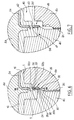
- Figures 9 to 11 show a distinctive mold variant essentially from that of FIGS. 4 to 8 in that it comprises a zone of necking 48.
- This necking area 48 is characterized by a boss 50 produced on the punch and having a height s.
- Figure 9 illustrates the constraints experienced by a sheet to come resting against the bearing surface 34 of the matrix 4a in a zone 46 with strong concavity. This area is close to the restraint 48, cutting means formed by the shear walls 20 and 22 and the periphery of the bearing surface 34.
- the sheet 2 is held by its peripheral zone 2c and the plastic material 1 is introduced in volume 16, under sheet 2.
- the sheet In an area where the matrix is concave, due to the tension which applied to it, the sheet tends in the absence of plastic to take off from the support surface 34. Thus, it will have to stretch to apply against the bearing surface 34 in the concave zone 46. The more the concavity is the higher the stretch.
- This concave zone 46 is also close to the means of cut formed by the shear walls 20 and 22, the concavity of the bearing surface 34 may cause defects to appear on the aspect face of the finished part. These faults may be due to a displacement of the cut to the bearing surface, tearing extending from the cuts 2nd at the bearing surface, but also at a material passage between the area 2a aspect of the sheet and this support surface 34. Indeed, the cut discontinuous induces a differential tension on the sheet between the zones cut out 2e and the sections 2d and in the event of a strong stretch, the decor area 2a may not apply over the entire concave area 46.
- the distance separating the punch 4b from the matrix 4a is equal to d 1 in the zone 46. It corresponds substantially to the movement that the sheet 2 will have to make, to the thickness of this sheet.
- the presence of the boss 50 makes it possible to reduce this distance to d 2 which is strictly less than dl. The stretching stresses of the sheet 2 are thus reduced, which makes it possible to flatten the decorative area 2a on the bearing surface without risk, or at least a lesser risk of deterioration of this sheet or of passage of plastic material between the of them.
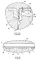
- the finished part 40 illustrated in FIG. 10 will thus have a substantially constant thickness e 1 outside the necking zone and a thickness e 2 in this necking zone 48.
- the difference between e 1 and e 2 corresponds to the height s of necking.
- the punch 4b comprises a succession of bosses 50 distant each other.
- the finished part will present a discontinuous necking.
- the width and spacing between the bosses consists of a trade-off between reducing the stretch applied to the sheet and the reduction of the mechanical characteristics of the finished part.
Applications Claiming Priority (2)
| Application Number | Priority Date | Filing Date | Title |
|---|---|---|---|
| FR9710086 | 1997-08-06 | ||
| FR9710086A FR2767084B1 (fr) | 1997-08-06 | 1997-08-06 | Procede et moule destines a l'habillage d'une piece plastique par une feuille-decor decoupee puis liberee, et piece |
Publications (2)
| Publication Number | Publication Date |
|---|---|
| EP0895846A1 true EP0895846A1 (de) | 1999-02-10 |
| EP0895846B1 EP0895846B1 (de) | 2003-03-05 |
Family
ID=9510091
Family Applications (1)
| Application Number | Title | Priority Date | Filing Date |
|---|---|---|---|
| EP19980401812 Expired - Lifetime EP0895846B1 (de) | 1997-08-06 | 1998-07-17 | Verfahren und Form zum Herstellen eines bekleideten Kunstoffgegenstandes mit einer geschnittenen und entspannten Dekorfolie. |
Country Status (4)
| Country | Link |
|---|---|
| EP (1) | EP0895846B1 (de) |
| DE (1) | DE69811791T2 (de) |
| ES (1) | ES2194285T3 (de) |
| FR (1) | FR2767084B1 (de) |
Cited By (3)
| Publication number | Priority date | Publication date | Assignee | Title |
|---|---|---|---|---|
| EP1700683A1 (de) * | 2005-03-11 | 2006-09-13 | Faurecia Interieur Industrie | Form und innenbekleidungsteil eines Kraftfahrzeugs |
| FR3011500A1 (fr) * | 2013-10-03 | 2015-04-10 | Valeo Systemes Thermiques | Procede de compression a chaud et surmoulage d'un insert composite et moule de compression a chaud et surmoulage associe |
| CN110640957A (zh) * | 2019-09-30 | 2020-01-03 | 无锡吉兴汽车声学部件科技有限公司 | 一种用于汽车顶篷模具的材料成型预压机构 |
Families Citing this family (1)
| Publication number | Priority date | Publication date | Assignee | Title |
|---|---|---|---|---|
| DE102014217510A1 (de) * | 2014-09-02 | 2016-03-03 | Röchling Automotive SE & Co. KG | Spritzgussverfahren zur Erzeugung eines gewebeverstärkten Spritzgussbauteils |
Citations (7)
| Publication number | Priority date | Publication date | Assignee | Title |
|---|---|---|---|---|
| US3184096A (en) * | 1961-10-04 | 1965-05-18 | Reynolds Metals Co | Container seal and opening means |
| EP0492052A2 (de) * | 1990-12-28 | 1992-07-01 | Nippla Co., Ltd. | In der Form etikettierter Behälter mit länglichem hervorstehendem Teil des Bodens und Verfahren zu seiner Herstellung |
| EP0543066A1 (de) * | 1991-11-22 | 1993-05-26 | Kasai Kogyo Co., Ltd. | Verkleidung für Fahrzeugtüren und dessen Herstellungsverfahren |
| DE4337697C1 (de) * | 1993-11-04 | 1994-11-17 | Lignotock Gmbh | Verfahren zur Herstellung von formstabilen, kaschierten Formteilen, wie Innenverkleidungen von Kraftfahrzeugen |
| EP0636464A1 (de) * | 1993-07-30 | 1995-02-01 | Eurostyle (S.A.) | Verfahren zum begrenzten Einfügen eines Dekors in einem thermoplastischen Substrat |
| WO1996003267A1 (en) * | 1994-07-21 | 1996-02-08 | Decoma International Inc. | Method and apparatus for manufacturing an injection-molded article with outer film secured thereto |
| EP0724942A1 (de) * | 1995-02-06 | 1996-08-07 | Compagnie Plastic Omnium | Verfahren und Formen zur Herstellung von Kunststoff-Verbundgegenständen mit einer Oberflächenschicht und dadurch hergestellte Gegenstände |
-
1997
- 1997-08-06 FR FR9710086A patent/FR2767084B1/fr not_active Expired - Fee Related
-
1998
- 1998-07-17 DE DE1998611791 patent/DE69811791T2/de not_active Expired - Fee Related
- 1998-07-17 EP EP19980401812 patent/EP0895846B1/de not_active Expired - Lifetime
- 1998-07-17 ES ES98401812T patent/ES2194285T3/es not_active Expired - Lifetime
Patent Citations (7)
| Publication number | Priority date | Publication date | Assignee | Title |
|---|---|---|---|---|
| US3184096A (en) * | 1961-10-04 | 1965-05-18 | Reynolds Metals Co | Container seal and opening means |
| EP0492052A2 (de) * | 1990-12-28 | 1992-07-01 | Nippla Co., Ltd. | In der Form etikettierter Behälter mit länglichem hervorstehendem Teil des Bodens und Verfahren zu seiner Herstellung |
| EP0543066A1 (de) * | 1991-11-22 | 1993-05-26 | Kasai Kogyo Co., Ltd. | Verkleidung für Fahrzeugtüren und dessen Herstellungsverfahren |
| EP0636464A1 (de) * | 1993-07-30 | 1995-02-01 | Eurostyle (S.A.) | Verfahren zum begrenzten Einfügen eines Dekors in einem thermoplastischen Substrat |
| DE4337697C1 (de) * | 1993-11-04 | 1994-11-17 | Lignotock Gmbh | Verfahren zur Herstellung von formstabilen, kaschierten Formteilen, wie Innenverkleidungen von Kraftfahrzeugen |
| WO1996003267A1 (en) * | 1994-07-21 | 1996-02-08 | Decoma International Inc. | Method and apparatus for manufacturing an injection-molded article with outer film secured thereto |
| EP0724942A1 (de) * | 1995-02-06 | 1996-08-07 | Compagnie Plastic Omnium | Verfahren und Formen zur Herstellung von Kunststoff-Verbundgegenständen mit einer Oberflächenschicht und dadurch hergestellte Gegenstände |
Cited By (4)
| Publication number | Priority date | Publication date | Assignee | Title |
|---|---|---|---|---|
| EP1700683A1 (de) * | 2005-03-11 | 2006-09-13 | Faurecia Interieur Industrie | Form und innenbekleidungsteil eines Kraftfahrzeugs |
| FR2882961A1 (fr) * | 2005-03-11 | 2006-09-15 | Faurecia Interieur Ind Snc | Moule de fabrication et piece d'habillage interieur d'automobile |
| FR3011500A1 (fr) * | 2013-10-03 | 2015-04-10 | Valeo Systemes Thermiques | Procede de compression a chaud et surmoulage d'un insert composite et moule de compression a chaud et surmoulage associe |
| CN110640957A (zh) * | 2019-09-30 | 2020-01-03 | 无锡吉兴汽车声学部件科技有限公司 | 一种用于汽车顶篷模具的材料成型预压机构 |
Also Published As
| Publication number | Publication date |
|---|---|
| FR2767084B1 (fr) | 1999-09-17 |
| ES2194285T3 (es) | 2003-11-16 |
| DE69811791D1 (de) | 2003-04-10 |
| DE69811791T2 (de) | 2003-12-18 |
| EP0895846B1 (de) | 2003-03-05 |
| FR2767084A1 (fr) | 1999-02-12 |
Similar Documents
| Publication | Publication Date | Title |
|---|---|---|
| EP1136239B1 (de) | Verfahren zur Herstellung eines verstärkten thermoplastischen Werkstücks und Form | |
| FR2492312A1 (fr) | Procede et appareil pour produire un objet moule creux en resine thermoplastique de synthese | |
| FR2627426A1 (fr) | Procede de fabrication de sieges moules integralement en mousse | |
| FR2651171A1 (fr) | Procede et dispositif de fabrication de moulure de cote de caisse de vehicule a partir de matiere thermoplastique extrudee, par refaconnage par compression a chaud dans un moule et bande obtenue. | |
| EP1066148B1 (de) | Verfahren zum herstellen eines kraftfahrzeug-bauteils durch einspritzen von kunststoffmaterial, verfahren zum sequenziellen einspritzen von kunststoffmaterial, form zur durchführung des verfahrens, und so hergestelltes bauteil | |
| EP0636464B1 (de) | Verfahren zum begrenzten Einfügen eines Dekors in einem thermoplastischen Substrat | |
| EP0895846B1 (de) | Verfahren und Form zum Herstellen eines bekleideten Kunstoffgegenstandes mit einer geschnittenen und entspannten Dekorfolie. | |
| EP0094268B1 (de) | Verfahren zum Herstellen von Kunststoffteilen überzogen mit einem Gewebe oder einem anderen flexibelen Überzugsmaterial durch Spritzgiessen und Vorrichtung zur Durchführung dieses Verfahrens | |
| FR2744947A1 (fr) | Procede d'habillage, par une feuille, d'une piece injectee, moule pour la mise en oeuvre du procede et piece obtenue | |
| EP0806274B1 (de) | Verfahren zur Verkleidung eines Kunststoffteiles mit einer während des Verfahrens geschnittenen Folie und hergestellter Teil | |
| EP2809495B1 (de) | Formeinheit zum thermoformen und verfahren zur herstellung von behältern | |
| EP1838515B1 (de) | Vorrichtung zum thermoformen von objekten mit basisflansch | |
| EP0724942A1 (de) | Verfahren und Formen zur Herstellung von Kunststoff-Verbundgegenständen mit einer Oberflächenschicht und dadurch hergestellte Gegenstände | |
| FR2673886A1 (fr) | Procede et dispositif de decoration d'une piece realisee par injection et piece decoree ainsi realisee. | |
| FR2744948A1 (fr) | Procede d'habillage d'une piece plastique injectee par une feuille dont on controle la tension et moule pour realiser la piece finie | |
| EP2127845B1 (de) | Verbessertes Herstellungsverfahren eines Teils, das eine Armstütze mit Komfortüberzug bildet | |
| FR2771045A1 (fr) | Procede d'insertion de decors dans une piece thermoplastique | |
| FR3075087A1 (fr) | Outillage pour moule de surmoulage | |
| EP0707533B1 (de) | Verfahren zur herstellung eines mehrschichtigen gegenstandes durch giessen und form zur herstellung eines solchen gegenstandes | |
| FR2784611A1 (fr) | Moule de fabrication d'une piece d'equipement notamment de vehicule automobile | |
| FR2751582A1 (fr) | Procede d'habillage d'une piece injectee par une feuille pincee lors du procede, et moule pour realiser la piece finie | |
| EP0925906B1 (de) | Vorrichtung zum Blasformen von Gegenständen die einen umhüllten Innenkörper aufweisen | |
| FR2846904A1 (fr) | Procede d'inclusion d'un revetement en medaillon sur une piece en matiere plastique | |
| FR2899512A1 (fr) | Dispositif de decoupe, dans le moule et avant l'ouverture de celui-ci, de la carotte d'injection d'une piece moulee, notamment d'une baguette de carrosserie automobile | |
| FR2768647A1 (fr) | Procede de fabrication d'une piece thermoplastique decoree |
Legal Events
| Date | Code | Title | Description |
|---|---|---|---|
| PUAI | Public reference made under article 153(3) epc to a published international application that has entered the european phase |
Free format text: ORIGINAL CODE: 0009012 |
|
| AK | Designated contracting states |
Kind code of ref document: A1 Designated state(s): DE ES FR GB IT PT SE |
|
| AX | Request for extension of the european patent |
Free format text: AL;LT;LV;MK;RO;SI |
|
| 17P | Request for examination filed |
Effective date: 19990802 |
|
| AKX | Designation fees paid |
Free format text: DE ES FR GB IT PT SE |
|
| 17Q | First examination report despatched |
Effective date: 20000524 |
|
| RTI1 | Title (correction) |
Free format text: METHOD AND MOULD FOR LINING A PLASTICS ARTICLE WITH A CUT AND RELIEVED DECORATIVE SHEET. |
|
| RTI1 | Title (correction) |
Free format text: METHOD AND MOULD FOR LINING A PLASTICS ARTICLE WITH A CUT AND RELIEVED DECORATIVE SHEET. |
|
| GRAH | Despatch of communication of intention to grant a patent |
Free format text: ORIGINAL CODE: EPIDOS IGRA |
|
| RTI1 | Title (correction) |
Free format text: METHOD AND MOULD FOR LINING A PLASTICS ARTICLE WITH A CUT AND RELIEVED DECORATIVE SHEET. |
|
| GRAH | Despatch of communication of intention to grant a patent |
Free format text: ORIGINAL CODE: EPIDOS IGRA |
|
| GRAA | (expected) grant |
Free format text: ORIGINAL CODE: 0009210 |
|
| AK | Designated contracting states |
Designated state(s): DE ES FR GB IT PT SE |
|
| PG25 | Lapsed in a contracting state [announced via postgrant information from national office to epo] |
Ref country code: IT Free format text: LAPSE BECAUSE OF FAILURE TO SUBMIT A TRANSLATION OF THE DESCRIPTION OR TO PAY THE FEE WITHIN THE PRESCRIBED TIME-LIMIT;WARNING: LAPSES OF ITALIAN PATENTS WITH EFFECTIVE DATE BEFORE 2007 MAY HAVE OCCURRED AT ANY TIME BEFORE 2007. THE CORRECT EFFECTIVE DATE MAY BE DIFFERENT FROM THE ONE RECORDED. Effective date: 20030305 |
|
| REG | Reference to a national code |
Ref country code: GB Ref legal event code: FG4D Free format text: NOT ENGLISH |
|
| REF | Corresponds to: |
Ref document number: 69811791 Country of ref document: DE Date of ref document: 20030410 Kind code of ref document: P |
|
| PG25 | Lapsed in a contracting state [announced via postgrant information from national office to epo] |
Ref country code: SE Free format text: LAPSE BECAUSE OF FAILURE TO SUBMIT A TRANSLATION OF THE DESCRIPTION OR TO PAY THE FEE WITHIN THE PRESCRIBED TIME-LIMIT Effective date: 20030605 Ref country code: PT Free format text: LAPSE BECAUSE OF FAILURE TO SUBMIT A TRANSLATION OF THE DESCRIPTION OR TO PAY THE FEE WITHIN THE PRESCRIBED TIME-LIMIT Effective date: 20030605 |
|
| GBT | Gb: translation of ep patent filed (gb section 77(6)(a)/1977) | ||
| REG | Reference to a national code |
Ref country code: ES Ref legal event code: FG2A Ref document number: 2194285 Country of ref document: ES Kind code of ref document: T3 |
|
| PLBE | No opposition filed within time limit |
Free format text: ORIGINAL CODE: 0009261 |
|
| STAA | Information on the status of an ep patent application or granted ep patent |
Free format text: STATUS: NO OPPOSITION FILED WITHIN TIME LIMIT |
|
| 26N | No opposition filed |
Effective date: 20031208 |
|
| PGFP | Annual fee paid to national office [announced via postgrant information from national office to epo] |
Ref country code: GB Payment date: 20040628 Year of fee payment: 7 |
|
| PGFP | Annual fee paid to national office [announced via postgrant information from national office to epo] |
Ref country code: ES Payment date: 20040708 Year of fee payment: 7 |
|
| PG25 | Lapsed in a contracting state [announced via postgrant information from national office to epo] |
Ref country code: GB Free format text: LAPSE BECAUSE OF NON-PAYMENT OF DUE FEES Effective date: 20050717 |
|
| PG25 | Lapsed in a contracting state [announced via postgrant information from national office to epo] |
Ref country code: ES Free format text: LAPSE BECAUSE OF NON-PAYMENT OF DUE FEES Effective date: 20050718 |
|
| GBPC | Gb: european patent ceased through non-payment of renewal fee |
Effective date: 20050717 |
|
| REG | Reference to a national code |
Ref country code: ES Ref legal event code: FD2A Effective date: 20050718 |
|
| PGFP | Annual fee paid to national office [announced via postgrant information from national office to epo] |
Ref country code: DE Payment date: 20070704 Year of fee payment: 10 |
|
| PGFP | Annual fee paid to national office [announced via postgrant information from national office to epo] |
Ref country code: FR Payment date: 20070730 Year of fee payment: 10 |
|
| PG25 | Lapsed in a contracting state [announced via postgrant information from national office to epo] |
Ref country code: DE Free format text: LAPSE BECAUSE OF NON-PAYMENT OF DUE FEES Effective date: 20090203 |
|
| REG | Reference to a national code |
Ref country code: FR Ref legal event code: ST Effective date: 20090331 |
|
| PG25 | Lapsed in a contracting state [announced via postgrant information from national office to epo] |
Ref country code: FR Free format text: LAPSE BECAUSE OF NON-PAYMENT OF DUE FEES Effective date: 20080731 |