EP0806274B1 - Verfahren zur Verkleidung eines Kunststoffteiles mit einer während des Verfahrens geschnittenen Folie und hergestellter Teil - Google Patents
Verfahren zur Verkleidung eines Kunststoffteiles mit einer während des Verfahrens geschnittenen Folie und hergestellter Teil Download PDFInfo
- Publication number
- EP0806274B1 EP0806274B1 EP19970400879 EP97400879A EP0806274B1 EP 0806274 B1 EP0806274 B1 EP 0806274B1 EP 19970400879 EP19970400879 EP 19970400879 EP 97400879 A EP97400879 A EP 97400879A EP 0806274 B1 EP0806274 B1 EP 0806274B1
- Authority
- EP
- European Patent Office
- Prior art keywords
- foil
- area
- sheet
- mould
- decorative
- Prior art date
- Legal status (The legal status is an assumption and is not a legal conclusion. Google has not performed a legal analysis and makes no representation as to the accuracy of the status listed.)
- Expired - Lifetime
Links
- 238000000034 method Methods 0.000 title claims description 38
- 239000004033 plastic Substances 0.000 title claims description 28
- 229920003023 plastic Polymers 0.000 title claims description 28
- 239000000463 material Substances 0.000 claims description 61
- 238000002347 injection Methods 0.000 claims description 30
- 239000007924 injection Substances 0.000 claims description 30
- 238000000465 moulding Methods 0.000 claims description 21
- 230000000694 effects Effects 0.000 claims description 9
- 238000004891 communication Methods 0.000 claims description 6
- FGUUSXIOTUKUDN-IBGZPJMESA-N C1(=CC=CC=C1)N1C2=C(NC([C@H](C1)NC=1OC(=NN=1)C1=CC=CC=C1)=O)C=CC=C2 Chemical compound C1(=CC=CC=C1)N1C2=C(NC([C@H](C1)NC=1OC(=NN=1)C1=CC=CC=C1)=O)C=CC=C2 FGUUSXIOTUKUDN-IBGZPJMESA-N 0.000 claims description 4
- 238000001816 cooling Methods 0.000 claims description 4
- 239000012530 fluid Substances 0.000 claims description 4
- 238000000926 separation method Methods 0.000 claims description 4
- 230000014759 maintenance of location Effects 0.000 claims description 2
- 239000011888 foil Substances 0.000 claims 22
- 238000005520 cutting process Methods 0.000 description 17
- 230000036961 partial effect Effects 0.000 description 5
- 230000002093 peripheral effect Effects 0.000 description 5
- 239000000243 solution Substances 0.000 description 5
- 235000014510 cooky Nutrition 0.000 description 4
- 230000000717 retained effect Effects 0.000 description 4
- 241000290142 Lotus berthelotii Species 0.000 description 3
- 238000005034 decoration Methods 0.000 description 3
- 230000002829 reductive effect Effects 0.000 description 3
- 239000012815 thermoplastic material Substances 0.000 description 3
- 241000287107 Passer Species 0.000 description 2
- 238000009825 accumulation Methods 0.000 description 2
- 238000007906 compression Methods 0.000 description 2
- 239000000835 fiber Substances 0.000 description 2
- 238000007493 shaping process Methods 0.000 description 2
- 241000287531 Psittacidae Species 0.000 description 1
- 210000003323 beak Anatomy 0.000 description 1
- 230000000295 complement effect Effects 0.000 description 1
- 230000007547 defect Effects 0.000 description 1
- 238000006073 displacement reaction Methods 0.000 description 1
- 238000009826 distribution Methods 0.000 description 1
- 239000004744 fabric Substances 0.000 description 1
- 239000006260 foam Substances 0.000 description 1
- 230000005484 gravity Effects 0.000 description 1
- 230000002452 interceptive effect Effects 0.000 description 1
- 238000004519 manufacturing process Methods 0.000 description 1
- 230000000873 masking effect Effects 0.000 description 1
- 239000011148 porous material Substances 0.000 description 1
- 238000003825 pressing Methods 0.000 description 1
- 230000000284 resting effect Effects 0.000 description 1
- 229920001169 thermoplastic Polymers 0.000 description 1
- 239000004416 thermosoftening plastic Substances 0.000 description 1
Images


Classifications
-
- B—PERFORMING OPERATIONS; TRANSPORTING
- B29—WORKING OF PLASTICS; WORKING OF SUBSTANCES IN A PLASTIC STATE IN GENERAL
- B29C—SHAPING OR JOINING OF PLASTICS; SHAPING OF MATERIAL IN A PLASTIC STATE, NOT OTHERWISE PROVIDED FOR; AFTER-TREATMENT OF THE SHAPED PRODUCTS, e.g. REPAIRING
- B29C45/00—Injection moulding, i.e. forcing the required volume of moulding material through a nozzle into a closed mould; Apparatus therefor
- B29C45/16—Making multilayered or multicoloured articles
- B29C45/1671—Making multilayered or multicoloured articles with an insert
-
- B—PERFORMING OPERATIONS; TRANSPORTING
- B29—WORKING OF PLASTICS; WORKING OF SUBSTANCES IN A PLASTIC STATE IN GENERAL
- B29C—SHAPING OR JOINING OF PLASTICS; SHAPING OF MATERIAL IN A PLASTIC STATE, NOT OTHERWISE PROVIDED FOR; AFTER-TREATMENT OF THE SHAPED PRODUCTS, e.g. REPAIRING
- B29C43/00—Compression moulding, i.e. applying external pressure to flow the moulding material; Apparatus therefor
- B29C43/02—Compression moulding, i.e. applying external pressure to flow the moulding material; Apparatus therefor of articles of definite length, i.e. discrete articles
- B29C43/18—Compression moulding, i.e. applying external pressure to flow the moulding material; Apparatus therefor of articles of definite length, i.e. discrete articles incorporating preformed parts or layers, e.g. compression moulding around inserts or for coating articles
- B29C43/183—Compression moulding, i.e. applying external pressure to flow the moulding material; Apparatus therefor of articles of definite length, i.e. discrete articles incorporating preformed parts or layers, e.g. compression moulding around inserts or for coating articles the preformed layer being a lining, e.g. shaped in the mould before compression moulding, or a preformed shell adapted to the shape of the mould
- B29C43/184—Compression moulding, i.e. applying external pressure to flow the moulding material; Apparatus therefor of articles of definite length, i.e. discrete articles incorporating preformed parts or layers, e.g. compression moulding around inserts or for coating articles the preformed layer being a lining, e.g. shaped in the mould before compression moulding, or a preformed shell adapted to the shape of the mould shaped by the compression of the material during moulding
-
- B—PERFORMING OPERATIONS; TRANSPORTING
- B29—WORKING OF PLASTICS; WORKING OF SUBSTANCES IN A PLASTIC STATE IN GENERAL
- B29C—SHAPING OR JOINING OF PLASTICS; SHAPING OF MATERIAL IN A PLASTIC STATE, NOT OTHERWISE PROVIDED FOR; AFTER-TREATMENT OF THE SHAPED PRODUCTS, e.g. REPAIRING
- B29C45/00—Injection moulding, i.e. forcing the required volume of moulding material through a nozzle into a closed mould; Apparatus therefor
- B29C45/14—Injection moulding, i.e. forcing the required volume of moulding material through a nozzle into a closed mould; Apparatus therefor incorporating preformed parts or layers, e.g. injection moulding around inserts or for coating articles
- B29C45/1418—Injection moulding, i.e. forcing the required volume of moulding material through a nozzle into a closed mould; Apparatus therefor incorporating preformed parts or layers, e.g. injection moulding around inserts or for coating articles the inserts being deformed or preformed, e.g. by the injection pressure
- B29C45/14221—Injection moulding, i.e. forcing the required volume of moulding material through a nozzle into a closed mould; Apparatus therefor incorporating preformed parts or layers, e.g. injection moulding around inserts or for coating articles the inserts being deformed or preformed, e.g. by the injection pressure by tools, e.g. cutting means
-
- B—PERFORMING OPERATIONS; TRANSPORTING
- B29—WORKING OF PLASTICS; WORKING OF SUBSTANCES IN A PLASTIC STATE IN GENERAL
- B29C—SHAPING OR JOINING OF PLASTICS; SHAPING OF MATERIAL IN A PLASTIC STATE, NOT OTHERWISE PROVIDED FOR; AFTER-TREATMENT OF THE SHAPED PRODUCTS, e.g. REPAIRING
- B29C45/00—Injection moulding, i.e. forcing the required volume of moulding material through a nozzle into a closed mould; Apparatus therefor
- B29C45/14—Injection moulding, i.e. forcing the required volume of moulding material through a nozzle into a closed mould; Apparatus therefor incorporating preformed parts or layers, e.g. injection moulding around inserts or for coating articles
- B29C45/1418—Injection moulding, i.e. forcing the required volume of moulding material through a nozzle into a closed mould; Apparatus therefor incorporating preformed parts or layers, e.g. injection moulding around inserts or for coating articles the inserts being deformed or preformed, e.g. by the injection pressure
- B29C45/14262—Clamping or tensioning means for the insert
-
- B—PERFORMING OPERATIONS; TRANSPORTING
- B29—WORKING OF PLASTICS; WORKING OF SUBSTANCES IN A PLASTIC STATE IN GENERAL
- B29C—SHAPING OR JOINING OF PLASTICS; SHAPING OF MATERIAL IN A PLASTIC STATE, NOT OTHERWISE PROVIDED FOR; AFTER-TREATMENT OF THE SHAPED PRODUCTS, e.g. REPAIRING
- B29C45/00—Injection moulding, i.e. forcing the required volume of moulding material through a nozzle into a closed mould; Apparatus therefor
- B29C45/14—Injection moulding, i.e. forcing the required volume of moulding material through a nozzle into a closed mould; Apparatus therefor incorporating preformed parts or layers, e.g. injection moulding around inserts or for coating articles
- B29C45/14336—Coating a portion of the article, e.g. the edge of the article
- B29C45/14344—Moulding in or through a hole in the article, e.g. outsert moulding
-
- B—PERFORMING OPERATIONS; TRANSPORTING
- B29—WORKING OF PLASTICS; WORKING OF SUBSTANCES IN A PLASTIC STATE IN GENERAL
- B29C—SHAPING OR JOINING OF PLASTICS; SHAPING OF MATERIAL IN A PLASTIC STATE, NOT OTHERWISE PROVIDED FOR; AFTER-TREATMENT OF THE SHAPED PRODUCTS, e.g. REPAIRING
- B29C45/00—Injection moulding, i.e. forcing the required volume of moulding material through a nozzle into a closed mould; Apparatus therefor
- B29C45/0025—Preventing defects on the moulded article, e.g. weld lines, shrinkage marks
- B29C2045/0032—Preventing defects on the moulded article, e.g. weld lines, shrinkage marks sequential injection from multiple gates, e.g. to avoid weld lines
-
- B—PERFORMING OPERATIONS; TRANSPORTING
- B29—WORKING OF PLASTICS; WORKING OF SUBSTANCES IN A PLASTIC STATE IN GENERAL
- B29C—SHAPING OR JOINING OF PLASTICS; SHAPING OF MATERIAL IN A PLASTIC STATE, NOT OTHERWISE PROVIDED FOR; AFTER-TREATMENT OF THE SHAPED PRODUCTS, e.g. REPAIRING
- B29C45/00—Injection moulding, i.e. forcing the required volume of moulding material through a nozzle into a closed mould; Apparatus therefor
- B29C45/14—Injection moulding, i.e. forcing the required volume of moulding material through a nozzle into a closed mould; Apparatus therefor incorporating preformed parts or layers, e.g. injection moulding around inserts or for coating articles
- B29C45/1418—Injection moulding, i.e. forcing the required volume of moulding material through a nozzle into a closed mould; Apparatus therefor incorporating preformed parts or layers, e.g. injection moulding around inserts or for coating articles the inserts being deformed or preformed, e.g. by the injection pressure
- B29C2045/14188—Injection moulding, i.e. forcing the required volume of moulding material through a nozzle into a closed mould; Apparatus therefor incorporating preformed parts or layers, e.g. injection moulding around inserts or for coating articles the inserts being deformed or preformed, e.g. by the injection pressure trimming the article in the mould
-
- B—PERFORMING OPERATIONS; TRANSPORTING
- B29—WORKING OF PLASTICS; WORKING OF SUBSTANCES IN A PLASTIC STATE IN GENERAL
- B29C—SHAPING OR JOINING OF PLASTICS; SHAPING OF MATERIAL IN A PLASTIC STATE, NOT OTHERWISE PROVIDED FOR; AFTER-TREATMENT OF THE SHAPED PRODUCTS, e.g. REPAIRING
- B29C45/00—Injection moulding, i.e. forcing the required volume of moulding material through a nozzle into a closed mould; Apparatus therefor
- B29C45/14—Injection moulding, i.e. forcing the required volume of moulding material through a nozzle into a closed mould; Apparatus therefor incorporating preformed parts or layers, e.g. injection moulding around inserts or for coating articles
- B29C45/14311—Injection moulding, i.e. forcing the required volume of moulding material through a nozzle into a closed mould; Apparatus therefor incorporating preformed parts or layers, e.g. injection moulding around inserts or for coating articles using means for bonding the coating to the articles
Definitions
- the subject of the invention is a method of dressing with at least one non-rigid decor sheet, essentially one aspect face of a support piece in plastic material (s), in a mold comprising essentially a first and a second part reserving between them a mold cavity.
- Non-rigid sheet should be understood as a flexible material (PVC, fabric or non-woven material, etc.) which may include a layer of foam or analogous, but which is deformable.
- the sheet can only be formed in the mold during the molding process of the whole part or have already been preformed beforehand so that it has before the setting work of the present process a first form close to that of the part of the mold with which it will come into contact.
- the invention relates more particularly to the production of a finished-piece comprising a decoration medallion covering only part of the aspect face.
- the problems inherent in this type of realization consist generally to correctly position the sheet, not to let appear on the finished part only a determined part of the sheet while allowing a satisfactory cohesion between the part covered with the appearance sheet and the part not covered.
- medallion the visible part of the sheet on the finished part and belonging to the aspect face
- the part of the support piece not coated with the sheet will be called “not molded” or “not covered “, while the part” under “the medallion will be said “overmolded” or “covered”.
- the problems posed by the wicking effect and the cohesion between the overmolded and non-overmolded parts will be largely resolved. Indeed, the number and distribution of material passages through the structure of the sheet can then be checked since they correspond to the places where cutting is carried out, in other words where the two elements are brought to the contact with each other. In addition, the cutting of the sheet being carried out in the molding cavity and putting the two volumes into fluid communication that it is made, the opening can be positioned precisely relative to in the mold.
- effect of wick a phenomenon consisting in the propagation of moisture by capillarity along the leaf, especially along the fibers when the sheet is made from fibers.
- EP-A-0 724 942 Admittedly, there is described in EP-A-0 724 942 a method recommending, to pass material through the sheet, to cut said sheet in the vicinity of the molding cavity using a blade fixed to one of the parts of the mold, but no opening is created in the cavity putting in communication the two volumes as soon as the cutting is completed.
- EP-A-0684120 discloses a relatively close process also consisting in stretching the sheet over cavities. from when no cutting of the sheet is planned, the structure of this sheet then bursts under the pressure of the material injected into the molding cavity.
- EP-A-0 636 464 teaches to pass the material plastic through the pores of the decor sheet.
- This solution requires to use a high porosity decor sheet, which risks among other things problem of creating material passages through the sheet at places unwanted, in particular to reveal the injected plastic where only the decor sheet should be visible.
- the invention aims to solve the aforementioned problems whatever the relative position of the covered part and the non-covered part covered.
- these two parts can be side by side, the part covered may surround the uncovered part or vice versa. They may also be in a configuration corresponding to a combination of these possibilities.
- the invention proposes that, when step d) and preferably also during step e), the pressure is injected plastic in the mold cavity.
- the finished part is then obtained directly, without requiring take the part during an additional molding operation to make the uncovered part with a satisfactory appearance.
- the injection of the material first "under" (that is to say opposite) the decor area allows you to set up the sheet by shaping it in the mold cavity.
- the second injection constitutes a resumption of flow from the first injection. This improves the appearance of the game uncovered and make larger uncovered parts.
- the second injection can be made at a higher pressure (from preferably 20 to 40 MPa depending on the material) in this uncovered part where the medallion is not present, while the pressure of the first injection will be more moderate (preferably from a few MPa to 20 MPa).
- the decor area is, said injection side, almost entirely covered with plastic material before cutting the sheet in step c). Therefore, before cutting the decor zone can be maintained thanks to the other zone, in particular its tension can be controlled, which will allow a good setting shape of the decor area. The almost complete covering of the decor area will freeze this formatting, thus avoiding that the decor area of the sheet does not deform after cutting.
- the opening is then carried out only when the shaping of the sheet and in particular of the decor area during the closing of the mold is completed. Therefore, the risk that the opening will move in the cavity of molding and is found on the aspect face is considerably reduced.
- the invention proposes that the sheet is placed in step b) between two elements of a cookie cutter device and during step c), instantly through the sheet an opening bringing one to contact on the other, the two elements of the cookie cutter device.
- the opening is thus easily carried out, with a positioning precise, reliable and fast, which shortens the time to obtain the room.
- the invention suggests that we maintain the two elements of the cookie cutter device in contact with each other until step f). We thus produce a finished part presenting a passage whose shape is determined from that of the punch.
- the invention proposes that after step c) the injection is checked against the decor area and at the outside of said decor area so that during said first and second injection stages, opposite forces are applied by matter on either side of the other zone, thus preventing it from appearing on the aspect face of the finished part.
- the invention proposes as a complementary solution or alternative that after step c), one creates in the immediate vicinity of the opening cut in the sheet, a swirl effect or restraint of the flow of the material injected into the first volume against its displacement natural towards the periphery of the second volume to prevent the other zone of the sheet does not appear on the aspect face.
- the invention suggests that from step b), the sheet is retained on the mold in a holding area of the sheet outside the decor area and during step c) the sheet is cut discontinuously so that the sheet is retained at least until step f). Controlling the movements of the sheet and therefore the quality of appearance of the medallion on the finished part is thus improved. This solution also makes it possible to prevent the cut being found on the aspect face.
- step c) after step c) the retention zone of the sheet so that its movement is prohibited.
- the invention further relates to a finished part obtained by the implementation of the process.
- a finished part obtained by the implementation of the process.
- it comprises a part covered where a non-rigid decor sheet covers an aspect face of a plastic support piece and an uncovered part where the sheet decoration is absent from the aspect face, and the covered part surrounds completely the part not covered.
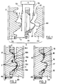
- FIG. 1 to 3 there is illustrated a mold 4 comprising a first movable part 4a and a second part consisting of a fixed part 4b and a bezel 4c (block in the form of a frame).
- the telescope 4c is linked to the fixed part 4b by jacks 5.
- the telescope could however alternatively be structurally linked to the movable part 4a of the mold via cylinders or the like.
- the mold 4 is in the open position - the movable part 4a and the fixed part 4b are widely spaced from each other - and the telescope came out - not pressing on the fixed part -.
- a sheet 2 is placed between the fixed part 4b and the telescope 4c by a first arm 6a of a robot 6.
- the sheet is then fixed on nails 8 in the upper part or by any other holding means.
- the rest of the sheet is then positioned by gravity, it being understood that the cutting plane is vertical.
- the window is partially closed.
- a distance d remains despite everything between the telescope 4c and the fixed part 4b of the mold.
- the sheet holding means constituted in particular by the nails 8 and the pinching of the sheet between the bezel 4c and the fixed part 4b of the mold are then active, that is to say that they retain a peripheral marginal zone of holding 2a of the sheet 2.
- the closing of the bezel being only partial, the sheet is not completely immobilized, that is to say that it can slide relative to the holding means. The tension of the sheet 2 is thus controlled.
- Thermoplastic material 1 intended to serve as a support for the finished part, is then injected from the fixed part 4b of the mold into a interior volume 16 located under sheet 2. During filling of the volume 16, the mold 4 is gradually closed by bringing the two parts 4a, 4b, so that an injection-compression is obtained of matter 1.
- a central zone 2c of the sheet 2 intended to appear on the aspect face of the finished part to constitute the medallion is applied by the thermoplastic material 1 against the part mobile 4a located opposite the first volume 16.
- the central area 2c is surrounded by a connection area 2b, itself surrounded by the area holding device 2a, the whole constituting the sheet 2.
- the mold has a cavity 17 comprising the volume 16 and a external volume 18 surrounding volume 16. These two volumes are here separated by the connection zone 2b of the decor sheet.
- volume 16 can be detected by measuring the volume of material injected, from the opening of the mold or using sensors event (pressure, heat flow, temperature sensor, optics or the like). When volume 16 is almost full, closing of the mold is then ordered and the fixed 4b and mobile 4a parts are come closer to each other.
- sensors event pressure, heat flow, temperature sensor, optics or the like.
- the telescope 4c has a protruding part 12 forming a stop bright like a "parrot's beak".
- This parrot beak cuts, at the limit of the connection zone 2b and of the peripheral holding zone 2a, the sheet 2 under the effect of the total closing pressure of the mold 4.
- the important thing is to cut the sheet 2 at least at the connection zone 2b, that is to say inside or at the limit of the cavity molding in order to connect volumes 16 and 18.
- connection zone 2b and therefore the central zone, are thus maintained since always linked by sections 2d to the holding zone 2a.
- the total closure of the mold prevents sliding of the holding zone 2a between the telescope 4c and the fixed part 4b of the mold.
- Connection area 2b therefore does not risk coming to bear against the movable part 4a of the mold, and to appear on the aspect face of the finished part.
- the 2nd cutouts mean that communication volume 16 and external volume 18, as soon as they are performed.
- the flow of material can thus continue from volume 16 covered with the medallion towards volume 18 where the aspect face of the finished part will not be covered.
- the material 1 is injected by means of nozzles 10a, 10b, 10c, 10d and 10e and gradually from the center of the area central 2c to the periphery thereof, then to the periphery of the uncovered part of the part after making the 2nd cuts in the leaf.
- the volume 16 will thus be filled first using the nozzles 10a, then 10b and 10c while volume 18 will be filled later using the nozzles 10d and 10th.
- This sequential injection is obtained using sensors previously mentioned - such as event sensors -, injection from a nozzle being controlled when the material front injected arrives at its level.
- This material front is ordered to be in constantly moving towards the periphery of cavity 17 and thus avoiding presence of visible weld lines on the finished part.
- the injection pressure of material 1 will be advantageously higher at the end of filling, especially when this only leaves via the nozzles 10c and 10d located in the volume 18. This improves the appearance qualities of the uncovered side - the more pressure is high the better the quality of appearance of the finished part, and notably less visible are the weld lines - without risking damage the medallion by too high an injection pressure.
- the finished part 40 is illustrated in FIG. 1 entered by a second arm 6b of the robot 6. Its support 42 composed of the thermoplastic material 1 being hardened, the finished part 40 is demolded by spacing the two parts of the mold. In this figure, the means for final cutting of the sheet 2 to separate the holding zone 2a from the finished part 40 have not been represented.
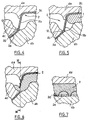
- FIG. 8 presents a variant where the cutting of the zone of connection 2b made using the "parrot beak" 22 is complete. (However, this cut could be partial - as illustrated in Figures 6 and 7.)
- the risk of the central area 2c moving is reduced by the fact that the material 1 being injected - in particular by sequential injection - first under the medallion, it has already cooled in this area and has "hardened” when the sheet is cut, that is to say substantially when the material front arrives in volume 18. This helps to maintain the medallion and prevent it from moving.
- connection zone 2b no longer being maintained by through the holding zone 2a, it must then be prevented that it can appear on the aspect face of the finished part.
- the part mobile 14a of the mold has a rib 28 against which the edge of the central zone 2c comes to bear in volume 16, this rib creating a offset 30 in volume 18.
- the limit between volumes 16 and 18 will be now defined by an imaginary line connecting the rib 28 and the beak of parrot 22.
- the fixed part 4b also has a step 26 such that the volume 18 has an enlarged area 34 limited by the recesses 26 and 30.
- the enlarged zone 34 is slightly longer than length of the connection zone 2b of the sheet.
- connection area 2b will be prevented from come on the aspect side, for two reasons:
- material 1 from volume 16 abuts against the dropout 26 and takes an illustrated vortex movement by arrow 32 so that it passes behind connection area 2b to enclose it and drown it, up to the level of the rib 28.
- This groove 28 prevents material 1 from interfering between medallion 2c and the moving part 14a of the mold.
- FIG. 9 shows a secondary cavity 38 communicating with the general molding cavity and produced in the fixed part 24b of the mold.
- the movable part of the mold 24a and the bezel 24c may be those illustrated previously.
- the cutting of the sheet may be partial or complete.
- This cavity 38 is produced at the edge of the volume 16 and serves as "flyweight", that is to say a reservoir of "too full” of material.
- said material extends around the injection points 10a, 10b, 10c.
- the connection area 2b risks to be impregnated with matter in certain places before others.
- the secondary cavity 38 creates a clearance for the material in waiting for the sheet to be cut and thus avoids the passage of material into preventing it from being compressed by accumulation in part of the injection volume. It therefore makes it possible to weight the filling differences of volume 16. At the end of injection, the cavity 38 is completely filled with material.
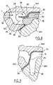
- Figures 10 to 13 illustrate a variant for achieving a part not covered with a decorative sheet entirely surrounded by a part covered with a decorative sheet.
- the elements corresponding to those of the previous figures have been identified by a number increased by 50.
- the mold 54 does not essentially differ from the mold 4 that in that the fixed part 54b comprises a movable core 54d actuated by a jack (not shown).
- the robot 56 introduces a sheet 53 into the mold between the movable part 54b and the bezel 54c.
- This sheet 53 is illustrated more precisely in FIG. 10. It has a recess 53a so that it forms a sort of crown between an inner edge 53b delimiting the recess and an edge exterior 53c. Around the recess the sheet 53 has notches 53d. extending radially into the sheet from the edge 53b.
- the robot fixes the sheet in the upper part on the nails 58.
- the core 54d is then inserted through the recess 53a in the sheet 53.
- the core 54d is then closed by bringing it closer to the fixed part 54b of the mold, such that so that an inner peripheral holding area 53f and in particular the inner edge 53a of the sheet is disposed between the core 54d and the part fixed 54b of the mold.
- the inner zone 53f is retained relative to the core 54d, the zone inner 53f then moves in substantially following the movement of the core 54d.
- the notches 53d will be found between the core 54d and the fixed part 54b of the mold. Consequently, the notches 53d facilitate the placing in place of the sheet, they prevent the sheet 53 from puckering when placed between the core 54d and the fixed part 54b, and is not likely to be visible on the finished piece.
- the closing of the telescope 54c is carried out as described previously in relation to the telescope 4c, substantially simultaneously with closing the core 54d.
- a peripheral peripheral holding area 53e and in particular the outer edge 53c are arranged between the bezel 54c and the fixed part 54b. We can more or less retain the outside area 53e by relative to the telescope 54c, as it has been described in relation to the core 54d, to apply the desired tension to sheet 53.
- the core 54d is then only partially closed, just as for the telescope 54c, there remains a distance d (substantially equal to d) between it and the fixed part 54b.
- the mold cavity 67 then has three volumes 66, 68 and 69 continuously separated by sheet 53, as illustrated in Figure 13.
- the material plastic 51 is then injected into volume 66 bringing a decorative area 53g of the sheet resting against the movable part 54a of the mold.
- the zones marked A and D correspond to what has was described previously in relation to detail IV.
- the zones marked B and C are similar to the zones marked respectively D and A, the nucleus 54d then playing a role similar to that of the bezel 54c.
- the subsequent steps to obtain the finished part 90 being by Consequently to those already described, they will not be explained again.
- the finished part 90 has a face of appearance 94 and includes a support piece 92 of plastic material covered with decor sheet 53 in part 90b of the room, which surrounds the uncovered part 90a and is surrounded by the uncovered part covered 90c.
- Figures 14 to 16 illustrate a variant for achieving a opening in a sheet.
- a mold 104 has a part fixed 104b and a movable part 104a, between which is formed a cavity molding 117.
- the two parts of the mold are at least partially closed.
- a sheet 102 is placed between these two parts of the mold and in particular in the molding cavity 117.
- An anvil 107a is arranged inside the movable part 104a and at the limit of the molding cavity 117.
- a hammer 107b having a cutting part 107d is disposed inside the fixed part 104b, in limit of the molding cavity 117 and opposite the anvil 107a.
- the hammer 107b slides with respect to the fixed part 104b.
- a slide 107c is interposed between the fixed part 104b and the hammer 107b.
- the assembly formed by the hammer 107b and the anvil 107a forms a cookie cutter device, that is to say that the approximation of the hammer 107b and anvil 107a causes the sheet 102 to be cut when it is arranged between them.
- the sheet continuously separates the mold cavity 117 into a first cavity 116 at the limit of which is disposed the hammer 107b and a second cavity 118 at the limit of which is disposed the anvil 107a.
- the contacting of the projecting part 107d of the hammer 107b and anvil 107a causes an opening 102a (illustrated in Figure 16) in sheet 102 immediately communicating fluid volumes 16 and 18.
- This opening surrounds a clipped area 102b of the sheet.
- the contact between the hammer and the anvil is made advantageously along a broken line. So the cut is discontinuous, and forms an opening 102a formed by a multitude of passage through the sheet 102. The cutting could however be continuous.
- the hammer 107b and the anvil 107a are then kept in contact with each other during material injection plastic 101 in volumes 116 and 118 and until the cooling of the room.
- the plastic material 101 is absent opposite and on the one hand and on the other side of the outlined area 102b of the sheet.
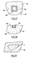
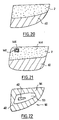
- FIG. 19 represents the aspect face of the part 40 of FIG. 1, the decoration sheet 2 being entirely surrounded by the uncovered part of the support 42.
- Figure 20 illustrates a variant of Figure 19 that allows also to obtain the process of the invention.
- the covered parts and not covered are then side by side.
- Figure 21 shows a part comprising a support part 42 uncovered and a part covered with a decorative sheet 2.
- the part covered includes a passage 146 surrounded by a flange 148 in plastic material made on the aspect face 144. It is in a way of a combination of what is illustrated in FIGS. 17 and 20.
- FIG. 22 represents the aspect face 94 of the finished part 90 of the Figure 11.
- the decor sheet 53 surrounds an uncovered part of the support 42 and is surrounded by another part not covered with the support.
- the invention is in no way limited to the modes of realization described above. So we could plan to link structurally the bezel at the movable part of the mold, without this modifying the process for obtaining the finished part. In particular, we can consider that the bezel and the fixed part of the mold are functionally linked.
Landscapes
- Engineering & Computer Science (AREA)
- Mechanical Engineering (AREA)
- Manufacturing & Machinery (AREA)
- Injection Moulding Of Plastics Or The Like (AREA)
- Moulds For Moulding Plastics Or The Like (AREA)
Claims (13)
- Verfahren zum Verkleiden mit mindestens einer nicht steifen Dekorfolie (2, 53, 102) von im wesentlichen einer Ansichtsseite (44, 94, 144) eines Stützteils (42, 92) aus Kunststoffmaterial(ien) (1; 51; 101), in einer Spritzform (4, 54, 104) mit im wesentlichen einem ersten (4b, 4c; 54b, 54c, 54d; 104b) und einem zweiten Teil (4a; 54a; 104a), die zwischen sich einen Formhohlraum (17; 67; 117) freihalten, wobei der erste Teil der Spritzform ebenfalls zwei Elemente (4b, 4c; 54b, 54c; 54b, 54d) aufweist, die bezüglich einander beweglich und dazu bestimmt sind, die Dekorfolie zu schneiden, indem sie miteinander in Kontakt kommen, um ein fertiges Teil (40; 90; 140) zu erhalten, das ein Dekormedaillon aufweist, wobei das Verfahren folgende Schritte aufweist:a) Einführen der Folie in die Spritzform zwischen die beweglichen Elemente, wobei die Folie einen Dekorbereich (2c; 53g), der für die Bildung des Medaillons bestimmt ist, und einen anderen Bereich aufweist,b) mindestens teilweises Schließen der Spritzform durch Annähern ihrer zwei Teile derart, daß die Folie eine fortlaufende Trennung des Formhohlraums in ein erstes (16; 66; 116) und ein zweites Volumen (18; 68, 69; 118) erzeugt,c) das miteinander in Kontaktbringen der zwei Elemente, um im Inneren des Formhohlraums mindestens eine Öffnung in die Folie an der Stelle des anderen Bereichs derart zu schneiden, daß die ersten und zweiten Volumina des Hohlraums in Fließmittelverbindung durch diese Öffnung gebracht werden, welche ihre Trennung von diesem Moment an unterbricht, um den Durchgang des Kunststoffmaterials quer durch sie zu erlauben,d) Einführen des Kunststoffmaterials in den Formhohlraum vor und/oder nach den Schritten b) und/oder c),e) Verteilen des Kunststoffmaterials nach dem Schritt c) in dem Formhohlraum, indem man es quer durch die Öffnung hindurchgehen läßt, um das Stützteil mit örtlich verkleideter Ansicht des Medaillons zu erhalten,f) Abkühlen des Teils,g) Öffnen der Spritzform und Ausstoßen des fertigen Teils.
- Verfahren nach Anspruch 1, dadurch gekennzeichnet, daß man während des Schrittes d) das Kunststoffmaterial in den Formhohlraum unter Druck einspritzt.
- Verfahren nach Anspruch 2, dadurch gekennzeichnet, daß:man während des Schrittes d) ein erstes Einspritzen des Kunststoffmaterials unter Druck gegenüber einer Seite des Dekorbereichs derart durchführt, daß der Dekorbereich der Folie unter Abstützung gegen einen der Teile der Spritzform zugeführt wird, der dazu bestimmt ist, sie aufzunehmen,man während des Schrittes e) das erste Einspritzen des Kunststoffmaterials fortsetzt, um das Kunststoffmaterial quer durch die Öffnungen durchgehen zu lassen, und man ein weiteres Einspritzen des Kunststoffmaterials unter Druck außerhalb des Dekorbereichs durchführt.
- Verfahren nach Anspruch 3, dadurch gekennzeichnet, daß der Dekorbereich (2c) auf der Einspritzseite beinahe völlig mit Kunststoffmaterial vor dem Schneiden der Folie während des Schrittes c) bedeckt wird.
- Verfahren nach Anspruch 3 oder 4, dadurch gekennzeichnet, daß man nach dem Schritt c) das Einspritzen gegenüber dem Dekorbereich und außerhalb des Dekorbereichs bis zum Verlauf des ersten und zweiten Injektionsschrittes kontrolliert, damit entgegengesetzte Belastungen durch das Kunststoffmaterial auf beiden Seiten des anderen Bereichs aufgebracht werden, um so zu vermeiden, daß es auf der Ansichtsseite des fertigen Stückes erscheint.
- Verfahren nach einem der vorhergehenden Ansprüche, dadurch gekennzeichnet, daßder erste Teil der Spritzform mindestens zwei Elemente (54b, 54d) aufweist,man eine Aussparung (53a) in der Folie realisiert,man während des Schrittes a) einen Bereich (53f) der Folie, welcher den äußeren Umfang dieser Aussparung bestimmt, zwischen die zwei Elemente des ersten Teils der Spritzform einführt, wo die Folie gehalten wird.
- Verfahren nach einem der vorhergehenden Ansprüche, dadurch gekennzeichnet, daßder erste Teil der Spritzform mindestens zwei Elemente (4b, 4c; 54b, 54c; 54b, 54d) aufweist,man während des Schrittes a) einen Bereich (2a; 53e; 53f) der Folie außerhalb des Dekorbereichs zwischen die zwei Elemente des ersten Teils der Spritzform einführt,das Schließen der Spritzform während des Schrittes b) nur teilweise erfolgt, wobei das völlige Verschließen der Spritzform während des Schrittes c) durchgeführt wird und das Schneiden der Folie durch Druck zwischen dem ersten (4b; 54b) und dem zweiten Element (4c; 54c; 54d) des ersten Teils der Spritzform erzeugt wird.
- Verfahren nach einem der vorhergehenden Ansprüche, dadurch gekennzeichnet, daß man die Folie bei dem Schritt b) zwischen zwei Elementen (107a, 107b) einer Lochstanzvorrichtung anordnet und man während des Schrittes c) sofort quer durch die Folie eine Öffnung (102a) realisiert, indem man die zwei Elemente der Lochstanzvorrichtung in Kontakt bringt.
- Verfahren nach Anspruch 8, dadurch gekennzeichnet, daß man die zwei Elemente der Lochstanzvorrichtung bis zu dem Schritt f) miteinander in Kontakt hält.
- Verfahren nach einem der vorhergehenden Ansprüche, dadurch gekennzeichnet, daß das erste Volumen gegenüber dem Dekorbereich liegt und daß man nach dem Schritt c) in unmittelbarer Nähe der in die Folie geschnittenen Öffnung eine Wirbelwirkung (32) oder eine Rückhaltewirkung (38) des Flusses des eingespritzten Kunststoffmaterials in dem ersten Volumen entgegen seiner natürlichen Verschiebung zu dem Umfang des zweiten Volumens erzeugt, um zu vermeiden, daß der andere Bereich der Folie auf der Ansichtsfläche erscheint.
- Verfahren nach Anspruch 5 oder 8, dadurch gekennzeichnet, daß man vor dem Schritt c) die Folie an der Spritzform in einem Haltebereich der Folie außerhalb des Dekorbereichs zurückhält und fortlaufend die Folie während des Schrittes c) schneidet, um den Dekorbereich und den Haltebereich zu trennen.
- Verfahren nach einem der Ansprüche 1 bis 10, dadurch gekennzeichnet, daß man ausgehend von dem Schritt b) die Folie an der Spritzform in einem Haltebereich der Folie außerhalb des Dekorbereichs zurückhält und man während des Schrittes c) die Folie in unterbrochener Weise derart schneidet, daß die Folie mindestens bis zu dem Schritt f) zurückgehalten wird.
- Verfahren nach Anspruch 12, dadurch gekennzeichnet, daß man nach dem Schritt c) den Haltebereich der Folie völlig derart zurückhält, daß ihre Verschiebung untersagt wird.
Priority Applications (1)
| Application Number | Priority Date | Filing Date | Title |
|---|---|---|---|
| US08/853,912 US6004497A (en) | 1996-05-10 | 1997-05-05 | Process for covering a plastics part with a foil cut during the process |
Applications Claiming Priority (2)
| Application Number | Priority Date | Filing Date | Title |
|---|---|---|---|
| FR9605858 | 1996-05-10 | ||
| FR9605858A FR2748414B1 (fr) | 1996-05-10 | 1996-05-10 | Procede d'habillage d'une piece thermoplastique injectee par une feuille decoupee au cours du procede, moule pour la mise en oeuvre du procede et piece obtenue |
Publications (3)
| Publication Number | Publication Date |
|---|---|
| EP0806274A2 EP0806274A2 (de) | 1997-11-12 |
| EP0806274A3 EP0806274A3 (de) | 1998-07-01 |
| EP0806274B1 true EP0806274B1 (de) | 2002-10-23 |
Family
ID=9492023
Family Applications (1)
| Application Number | Title | Priority Date | Filing Date |
|---|---|---|---|
| EP19970400879 Expired - Lifetime EP0806274B1 (de) | 1996-05-10 | 1997-04-18 | Verfahren zur Verkleidung eines Kunststoffteiles mit einer während des Verfahrens geschnittenen Folie und hergestellter Teil |
Country Status (4)
| Country | Link |
|---|---|
| EP (1) | EP0806274B1 (de) |
| DE (1) | DE69716507T2 (de) |
| ES (1) | ES2187735T3 (de) |
| FR (1) | FR2748414B1 (de) |
Families Citing this family (7)
| Publication number | Priority date | Publication date | Assignee | Title |
|---|---|---|---|---|
| DE19731561B4 (de) * | 1997-07-23 | 2014-11-06 | Johnson Controls Interiors Gmbh & Co. Kg | Formwerkzeug zum Herstellen von Formteilen |
| DE19825844C2 (de) * | 1998-06-10 | 2000-10-05 | Muerdter Werkzeug Und Formenba | Verfahren und Vorrichtung zur Herstellung eines Formteils |
| FR2785244B1 (fr) | 1998-10-29 | 2000-12-08 | Sommer Allibert Lignotock | Procede d'obtention d'une piece d'equipement interieur de vehicule et piece obtenue |
| FR2846904A1 (fr) * | 2002-11-08 | 2004-05-14 | Cera | Procede d'inclusion d'un revetement en medaillon sur une piece en matiere plastique |
| DE102004012467B4 (de) | 2004-03-15 | 2007-05-31 | Daimlerchrysler Ag | Fahrzeug-Folienbauteil und Verfahren zu dessen Herstellung |
| DE102006003305B3 (de) | 2006-01-23 | 2007-08-02 | Infineon Technologies Ag | Vorrichtung und Verfahren zur Herstellung eines Gegenstands mittels Kunststoff-Formtechnik |
| FR3047685B1 (fr) * | 2016-02-11 | 2018-03-16 | Institut De Recherche Technologique Jules Verne | Dispositif de fabrication, par moulage par injection, d'une piece comportant un insert |
Family Cites Families (8)
| Publication number | Priority date | Publication date | Assignee | Title |
|---|---|---|---|---|
| US3184096A (en) * | 1961-10-04 | 1965-05-18 | Reynolds Metals Co | Container seal and opening means |
| AU428765B2 (en) * | 1969-06-02 | 1972-09-29 | A. J. Parkes & Co. Pty. Ltd | Improvements in buttons, badges andthe like |
| NL8003800A (nl) * | 1980-07-01 | 1982-02-01 | Stamicarbon | Werkwijze en inrichting voor het spuitgieten van kunststoffen. |
| DE69200001D1 (de) * | 1992-02-11 | 1993-06-17 | Neyr Plastiques Sa | Verfahren zur herstellung von geformten gegenstaenden mit einer starren unterlage und einer biegsamen beschichtung. |
| IT1256901B (it) * | 1992-07-28 | 1995-12-27 | Itw Fastex Italia Spa | Procedimento per il costampaggio di un inserto metallico realizzante una pluralita' di circuiti elettrici in un elemento in materiale plastico sintetico. |
| FR2708512B1 (fr) * | 1993-07-30 | 1995-10-06 | Eurostyle Sa | Procédé d'insertion délimitée d'un décor dans un support thermoplastique. |
| FR2720320B1 (fr) * | 1994-05-26 | 1996-09-20 | Cera | Procédé d'inclusion d'un décor, notamment textile, dans une pièce en matière plastique. |
| FR2730185B1 (fr) * | 1995-02-06 | 1997-03-14 | Plastic Omnium Cie | Procede de realisation de pieces composites en matiere plastique comportant un revetement de surface, moules pour sa mise en oeuvre et pieces composites ainsi obtenues |
-
1996
- 1996-05-10 FR FR9605858A patent/FR2748414B1/fr not_active Expired - Fee Related
-
1997
- 1997-04-18 EP EP19970400879 patent/EP0806274B1/de not_active Expired - Lifetime
- 1997-04-18 ES ES97400879T patent/ES2187735T3/es not_active Expired - Lifetime
- 1997-04-18 DE DE1997616507 patent/DE69716507T2/de not_active Expired - Fee Related
Also Published As
| Publication number | Publication date |
|---|---|
| FR2748414A1 (fr) | 1997-11-14 |
| FR2748414B1 (fr) | 1998-06-26 |
| DE69716507D1 (de) | 2002-11-28 |
| EP0806274A2 (de) | 1997-11-12 |
| EP0806274A3 (de) | 1998-07-01 |
| DE69716507T2 (de) | 2003-02-27 |
| ES2187735T3 (es) | 2003-06-16 |
Similar Documents
| Publication | Publication Date | Title |
|---|---|---|
| EP1136239B1 (de) | Verfahren zur Herstellung eines verstärkten thermoplastischen Werkstücks und Form | |
| EP0894046B1 (de) | Verfahren zum herstellen eines fertigen bauteiles mit einem bereich der fähig ist ein durchgang zu bilden, fertiges bauteil und entsprechende einheit | |
| FR2615783A1 (fr) | Produit moule par injection presentant une partie partiellement mince et procede et appareil pour sa fabrication | |
| CA2326656C (fr) | Moule de bande de roulement | |
| EP0806274B1 (de) | Verfahren zur Verkleidung eines Kunststoffteiles mit einer während des Verfahrens geschnittenen Folie und hergestellter Teil | |
| FR2565889A1 (fr) | Procede de moulage d'un conteneur a paroi mince moyennant l'utilisation d'une resine synthetique | |
| EP2532532B1 (de) | Vorrichtung und Verfahren zur Herstellung eines Artikels aus Hohlglas | |
| EP0636464B1 (de) | Verfahren zum begrenzten Einfügen eines Dekors in einem thermoplastischen Substrat | |
| EP1182023B1 (de) | Verfahren zur Herstellung eines lasttragenden Teils aus expandiertem Polystyrol, und durch das Verfahren herstellbares Teil | |
| EP0724942A1 (de) | Verfahren und Formen zur Herstellung von Kunststoff-Verbundgegenständen mit einer Oberflächenschicht und dadurch hergestellte Gegenstände | |
| EP0895846B1 (de) | Verfahren und Form zum Herstellen eines bekleideten Kunstoffgegenstandes mit einer geschnittenen und entspannten Dekorfolie. | |
| EP2611706B1 (de) | Form zur herstellung einer hülle für einen behälter wie eine flasche oder einen flakon mittels spritzgussverfahren, und formverfahren mit einer derartigen form | |
| FR2771045A1 (fr) | Procede d'insertion de decors dans une piece thermoplastique | |
| FR2744948A1 (fr) | Procede d'habillage d'une piece plastique injectee par une feuille dont on controle la tension et moule pour realiser la piece finie | |
| CH389232A (fr) | Procédé de fabrication d'une pièce moulée comportant des signes et machine pour la mise en oeuvre de ce procédé | |
| FR2552702A1 (fr) | Procede de fabrication de talons de chaussures, moules et ebauches de revetement pour la mise en oeuvre du procede, poincon pour la preparation des ebauches, ainsi que talons et chaussures ainsi obtenus | |
| FR2784611A1 (fr) | Moule de fabrication d'une piece d'equipement notamment de vehicule automobile | |
| EP0925906B1 (de) | Vorrichtung zum Blasformen von Gegenständen die einen umhüllten Innenkörper aufweisen | |
| FR2768648A1 (fr) | Procede et moule pour realiser une piece finie comprenant une piece-support recouverte par une feuille-decor et presentant un passage, ainsi que la piece finie | |
| FR2751582A1 (fr) | Procede d'habillage d'une piece injectee par une feuille pincee lors du procede, et moule pour realiser la piece finie | |
| FR2705247A1 (fr) | Procédé pour fabriquer un ski en forme. | |
| FR3126331A1 (fr) | Outil de coulée, procédé et utilisation d’un outil de coulée pour le post-moulage d’une pièce coulée, et pièce coulée | |
| FR2846904A1 (fr) | Procede d'inclusion d'un revetement en medaillon sur une piece en matiere plastique | |
| FR2899512A1 (fr) | Dispositif de decoupe, dans le moule et avant l'ouverture de celui-ci, de la carotte d'injection d'une piece moulee, notamment d'une baguette de carrosserie automobile | |
| FR3096291A1 (fr) | Procédé de fabrication d’une pièce tridimensionnelle composite et pièce obtenue |
Legal Events
| Date | Code | Title | Description |
|---|---|---|---|
| PUAI | Public reference made under article 153(3) epc to a published international application that has entered the european phase |
Free format text: ORIGINAL CODE: 0009012 |
|
| AK | Designated contracting states |
Kind code of ref document: A2 Designated state(s): DE ES FR GB IT PT SE |
|
| PUAL | Search report despatched |
Free format text: ORIGINAL CODE: 0009013 |
|
| AK | Designated contracting states |
Kind code of ref document: A3 Designated state(s): DE ES FR GB IT PT SE |
|
| 17P | Request for examination filed |
Effective date: 19981207 |
|
| 17Q | First examination report despatched |
Effective date: 20010117 |
|
| GRAG | Despatch of communication of intention to grant |
Free format text: ORIGINAL CODE: EPIDOS AGRA |
|
| GRAG | Despatch of communication of intention to grant |
Free format text: ORIGINAL CODE: EPIDOS AGRA |
|
| GRAH | Despatch of communication of intention to grant a patent |
Free format text: ORIGINAL CODE: EPIDOS IGRA |
|
| GRAH | Despatch of communication of intention to grant a patent |
Free format text: ORIGINAL CODE: EPIDOS IGRA |
|
| GRAA | (expected) grant |
Free format text: ORIGINAL CODE: 0009210 |
|
| AK | Designated contracting states |
Kind code of ref document: B1 Designated state(s): DE ES FR GB IT PT SE |
|
| PG25 | Lapsed in a contracting state [announced via postgrant information from national office to epo] |
Ref country code: IT Free format text: LAPSE BECAUSE OF FAILURE TO SUBMIT A TRANSLATION OF THE DESCRIPTION OR TO PAY THE FEE WITHIN THE PRE;WARNING: LAPSES OF ITALIAN PATENTS WITH EFFECTIVE DATE BEFORE 2007 MAY HAVE OCCURRED AT ANY TIME BEFORE 2007. THE CORRECT EFFECTIVE DATE MAY BE DIFFERENT FROM THE ONE RECORDED.SCRIBED TIME-LIMIT Effective date: 20021023 |
|
| REG | Reference to a national code |
Ref country code: GB Ref legal event code: FG4D Free format text: NOT ENGLISH |
|
| REF | Corresponds to: |
Ref document number: 69716507 Country of ref document: DE Date of ref document: 20021128 |
|
| PG25 | Lapsed in a contracting state [announced via postgrant information from national office to epo] |
Ref country code: SE Free format text: LAPSE BECAUSE OF FAILURE TO SUBMIT A TRANSLATION OF THE DESCRIPTION OR TO PAY THE FEE WITHIN THE PRESCRIBED TIME-LIMIT Effective date: 20030123 Ref country code: PT Free format text: LAPSE BECAUSE OF FAILURE TO SUBMIT A TRANSLATION OF THE DESCRIPTION OR TO PAY THE FEE WITHIN THE PRESCRIBED TIME-LIMIT Effective date: 20030123 |
|
| GBT | Gb: translation of ep patent filed (gb section 77(6)(a)/1977) |
Effective date: 20030212 |
|
| REG | Reference to a national code |
Ref country code: ES Ref legal event code: FG2A Ref document number: 2187735 Country of ref document: ES Kind code of ref document: T3 |
|
| PLBE | No opposition filed within time limit |
Free format text: ORIGINAL CODE: 0009261 |
|
| STAA | Information on the status of an ep patent application or granted ep patent |
Free format text: STATUS: NO OPPOSITION FILED WITHIN TIME LIMIT |
|
| 26N | No opposition filed |
Effective date: 20030724 |
|
| PGFP | Annual fee paid to national office [announced via postgrant information from national office to epo] |
Ref country code: GB Payment date: 20040329 Year of fee payment: 8 |
|
| PGFP | Annual fee paid to national office [announced via postgrant information from national office to epo] |
Ref country code: ES Payment date: 20040413 Year of fee payment: 8 |
|
| PGFP | Annual fee paid to national office [announced via postgrant information from national office to epo] |
Ref country code: FR Payment date: 20040427 Year of fee payment: 8 |
|
| PG25 | Lapsed in a contracting state [announced via postgrant information from national office to epo] |
Ref country code: GB Free format text: LAPSE BECAUSE OF NON-PAYMENT OF DUE FEES Effective date: 20050418 |
|
| PG25 | Lapsed in a contracting state [announced via postgrant information from national office to epo] |
Ref country code: ES Free format text: LAPSE BECAUSE OF NON-PAYMENT OF DUE FEES Effective date: 20050419 |
|
| GBPC | Gb: european patent ceased through non-payment of renewal fee |
Effective date: 20050418 |
|
| PG25 | Lapsed in a contracting state [announced via postgrant information from national office to epo] |
Ref country code: FR Free format text: LAPSE BECAUSE OF NON-PAYMENT OF DUE FEES Effective date: 20051230 |
|
| REG | Reference to a national code |
Ref country code: FR Ref legal event code: ST Effective date: 20051230 |
|
| REG | Reference to a national code |
Ref country code: ES Ref legal event code: FD2A Effective date: 20050419 |
|
| PGFP | Annual fee paid to national office [announced via postgrant information from national office to epo] |
Ref country code: DE Payment date: 20070327 Year of fee payment: 11 |
|
| PG25 | Lapsed in a contracting state [announced via postgrant information from national office to epo] |
Ref country code: DE Free format text: LAPSE BECAUSE OF NON-PAYMENT OF DUE FEES Effective date: 20081101 |