EP0895730A2 - Iron - Google Patents
Iron Download PDFInfo
- Publication number
- EP0895730A2 EP0895730A2 EP98108168A EP98108168A EP0895730A2 EP 0895730 A2 EP0895730 A2 EP 0895730A2 EP 98108168 A EP98108168 A EP 98108168A EP 98108168 A EP98108168 A EP 98108168A EP 0895730 A2 EP0895730 A2 EP 0895730A2
- Authority
- EP
- European Patent Office
- Prior art keywords
- chambers
- tool
- iron according
- iron
- water
- Prior art date
- Legal status (The legal status is an assumption and is not a legal conclusion. Google has not performed a legal analysis and makes no representation as to the accuracy of the status listed.)
- Withdrawn
Links
Images


Classifications
-
- A—HUMAN NECESSITIES
- A43—FOOTWEAR
- A43D—MACHINES, TOOLS, EQUIPMENT OR METHODS FOR MANUFACTURING OR REPAIRING FOOTWEAR
- A43D95/00—Shoe-finishing machines
- A43D95/02—Machines for treating or smoothing shoe uppers to remove wrinkles, folds, or the like
Definitions
- the present invention relates to an iron.
- the present invention relates to an iron of the type suitable to be used in footwear and leatherware sectors.
- the ironing operation is made by hand by qualified personnel, as it requires particular ability and attention; the application of a body heated at a high temperature may in fact damage leather irreversibly, forming burnings on the same. It is easy to understand that, especially in the presence of artefacts from precious leathers, for instance, reptilian skin, an unsatisfactory ironing intervention may cause a relevant economic loss.
- the person that performs the ironing provides each time to humidify the part to be submitted to the ironing treatment with water or chemical substances; this avoids the formation of burnings on leather.
- Object of this invention is to obviate the aforesaid drawback.
- object of this invention is to realise an iron utilisable in footwear and leatherware sectors suitable to avoid the manual humidifying intervention by the operator.
- a further object of the invention is to realise an iron as defined above, autonomously integrating means for an adequate humidifying of the artefacts, that can be activated, when necessary, in a simple, prompt and calibrated manner by the operator.
- a not least object of the invention is to realise an iron capable of delivering constantly and quickly atomised liquid, avoiding, as a consequence, the distribution of hot fluid on the artefacts to be treated.
- a further object of the invention is to provide users with an iron for footwear and leatherware products suitable to ensure a high level of resistance and reliability in the time, and also such as to be easily and economically realisable.
- a fluid feeding system is associated that allows the calibrated administration of liquid to the heated tool of said iron.
- the iron of the present invention which, being especially suitable to be used in footwear and leatherware sectors, comprises a tool, connected to a grip and handling body, made from metal and provided internally with a plurality of ducts and seats forming one or more chambers for the liquid to be atomised and an adjoining cavity for a heating body, at least one of said chambers having a partly or entirely irregular internal surface, communicating with the outside of the tool through a nozzle.
- the iron of the present invention is basically constituted by a body 12 having an elongated shape, with a section, by way of example circular or ovoid, forming the support and the handle of the heating body, or tool 14, connected to the front end of said body 12 by means known in the art, such as screws 16.
- Tool 14 whose shape is of a conventional type and is shown by way of example by the figures, is obtained from metal, from instance brass, by casting, and, according to the invention, is provided in its inside with a plurality of ducts and seats variously located and developed, to cause a controlled and calibrate steam delivery through an end nozzle.
- tool 14 has, according to a preferred embodiment, a couple of tubular ducts communicating with one another which constitute as many chambers 18, 20 for the atomisation of the fluid, as well as a cavity 22 forming the seat housing a conventional heating body 24 and a hole 26 for a thermocouple 28 connected to said body 24.
- Chambers 18, 20, preferably parallel to one another may be aligned on the same plane in the lower part of tool 14, as shown in Figure 3, or superposed, as shown in Figures 4 and 5.
- the heating body 24 is advantageously constituted by an electric resistor or the like, fed through a conventional cable 30 which develops in body 12 forming the handle of iron 10 and comes out from the back of the same, to connect with the mains.
- chambers 18, 20 The longitudinal development of chambers 18, 20 is such that at least one of them reaches the portion near to the front end of tool 14, in whose correspondence a small opening 32 is formed that constitutes the steam outlet nozzle. Chambers 18, 20, communicate radially between one another though one or more connecting openings 34; in the preferred embodiment, opening 34 is the only one, and is formed near the back front, opposite to nozzle 32, of chambers 18, 20.
- the walls of said chambers 18, 20 have a rough surface 36, as shown in detail in Figure 4; the surface roughness, which is preferably formed by a continuous threading, may be alternatively obtained by broaching interventions or the like, or directly during the casting of tool 14.
- This configuration of the walls of the chambers 18, 20 which markedly increases the contact surface between the fluid and the metal in the inside of tool 14, is particularly effective as it substantially limits the outlet from nozzle 32 of the non atomised fluid, contrasting its tendency to the known calefaction phenomenon.
- tool 14 is heated by body 24 to a temperature higher than 100°C, which may exceed even 200°C; the drops of fluid, generally water, that are let in evaporation chambers 18, 20, would be immediately enveloped by a steam layer about the hot metal surface and would have the tendency to "skipping", without keeping in contact with said surface.
- water droplets might come out, together with steam, with ensuing danger of deteriorating the artefact parts that are being ironed.
- Said covering is formed, for instance, by a thin layer of inorganic salt, calcium chloride or the like, which is dissolved in the fluid and deposits spontaneously and homogeneously in the unevenness of the walls of chambers 18, 20, after a limited use of tool 14; obviously, the covering may be obtained before the use of tool 14 feeding chambers 18, 20, at suitably additivated water temperature.
- said covering is schematised by 38 and constitutes a thin layer that covers, in a substantially homogeneous manner, the whole rough surface of atomising chambers 18, 20 of tool 14.
- Said bush has preferably an inner diameter such as to allow the stabilisation by simple mechanical interference in the mouths of said chambers, without excluding however the possibility of realising the connection by means of glues or other systems.
- the inner diameter of bush 42 conditions suitably the size of the tool to be inserted in chambers 18, 20, to carry out the cleaning; the tool, consequently, will have a diameter such as no to notch the tops of the rough surface of said chambers.
- a feed system suitable to mix with air the fluid prior to its entering chambers 18, 20, through an atomising device.
- Said atomising device indicated by 44 in Figures 5 and 7, is constituted by a tubular body 46, wherein two separate ducts 40, 50 are obtained, for delivering air and water, flowing into a mixing chamber 52.
- Body 46 extends, before said chamber 52, into a tube 54 having a smaller diameter, whose front end 56 is fitted in and restrained, with known means, in the mouth of one of chambers 18, 20 of tool 14.
- the front end 56 of tube 54 is fitted in chamber 18 which develops above chamber 20 in tool 12.
- Ducts 48, 50 are connected through conventional connecting means to the feeding system, schematised as a whole by 60 in Figure 7.
- Said system consists of a circuit fed with air, through a filter 64 and a pressure reducer 62, which is regulated as concerns both pressure and capacity.
- the circuit develops into two distinct branches 66, 68, the first of which is connected, with the interposition of an electrovalve 70, to duct 48 of the atomising device 44.
- the second branch 68 of the circuit enter a water-containing tank 72, exits from the same and connects, with the interposition of an electrovalve 74, to duct 50 of said atomising device 44.
- a pressure control means such as for instance a pressure-gauge 76, allows the control of air pressure in the circuit, which is preferably comprised between 0.005 and 0.5 bar.
- the feeding system is activated, for instance through button 12' protruding from the handle-body 12 of iron 10, the system is caused to operated thanks to the simultaneous opening of electrovalves 70, 74, respectively located near branches 66, 68, and the ensuing separate entering of a quantity of air and water in chamber 52 of the atomising device 44, wherein it mixes.
- the pressured air-water mix passes then into tube 54 and, through its front end 56, into chamber 18 of tool 14.
- the hole of tube 14 and the related front end 56 is suitably calibrated to realise the atomisation of the air-water mix.
- electrovalve 74 of the water-delivering branch closes, while electrovalve 70 of the air-delivering branch remains advantageously open for a fraction of second, so as to eliminate water residues from device 44.
- the iron of the present invention allows the substantially immediate delivery from nozzle 32 of tool 14 of steam to be locally distributed on the artefact to be ironed; no danger exists of delivering hot water drops, given the presence in tool 14 of labyrinth-like chambers 18, 20, their internal configuration and the related covering.
- the operator who performs the ironing can work rapidly, being not obliged to humidify by hand the artefact before ironing the same with the heated tool 14.
- the connection of iron 10 to mains 60, through the atomising device 44 allows to exactly dose minimum water quantities and to accelerate the atomisation in the inside of tool 14.
- tool 14 may have a different number of evaporation chambers 18, 19, not necessarily having a rectilinear development, to form a more or less extended labyrinth, and the roughness of the internal walls of said chambers may be discontinuous and/or differentiated, to form more or less deep unevennesses 40.
- the fluid feeding iron 10 may be obtained by any means, even though the connection to a system 60 of the above described type is preferred.
Landscapes
- Nozzles (AREA)
- Footwear And Its Accessory, Manufacturing Method And Apparatuses (AREA)
- Treatment And Processing Of Natural Fur Or Leather (AREA)
- Soft Magnetic Materials (AREA)
Abstract
Description
- The present invention relates to an iron.
- More particularly, the present invention relates to an iron of the type suitable to be used in footwear and leatherware sectors.
- As is known, in the aforesaid sectors, there are used for the finishing operations of the artefacts several tools, including a special iron. This tool is utilised to eliminate, for instance in shoes, the possible localised curlings of leather, so as to obtain aesthetically perfect products.
- The ironing operation is made by hand by qualified personnel, as it requires particular ability and attention; the application of a body heated at a high temperature may in fact damage leather irreversibly, forming burnings on the same. It is easy to understand that, especially in the presence of artefacts from precious leathers, for instance, reptilian skin, an unsatisfactory ironing intervention may cause a relevant economic loss.
- In order to prevent this danger, usually the person that performs the ironing provides each time to humidify the part to be submitted to the ironing treatment with water or chemical substances; this avoids the formation of burnings on leather.
- The above necessity, which causes the formation of a light insulating layer between the ironing tool and the part of the artefact to be treated, involves, as can be understood, an increase in production costs. On the other hand, it would not be possible to use conventional steam-delivering tools as there would easily form on the surface to be treated an uncontrolled plurality of drops of hot liquid, or condensate, that are prejudicial to leather.
- Object of this invention is to obviate the aforesaid drawback.
- More particularly, object of this invention is to realise an iron utilisable in footwear and leatherware sectors suitable to avoid the manual humidifying intervention by the operator.
- A further object of the invention is to realise an iron as defined above, autonomously integrating means for an adequate humidifying of the artefacts, that can be activated, when necessary, in a simple, prompt and calibrated manner by the operator.
- A not least object of the invention is to realise an iron capable of delivering constantly and quickly atomised liquid, avoiding, as a consequence, the distribution of hot fluid on the artefacts to be treated.
- A further object of the invention is to provide users with an iron for footwear and leatherware products suitable to ensure a high level of resistance and reliability in the time, and also such as to be easily and economically realisable.
- Advantageously, to the iron of the present invention a fluid feeding system is associated that allows the calibrated administration of liquid to the heated tool of said iron.
- These and still other objects are achieved by the iron of the present invention, which, being especially suitable to be used in footwear and leatherware sectors, comprises a tool, connected to a grip and handling body, made from metal and provided internally with a plurality of ducts and seats forming one or more chambers for the liquid to be atomised and an adjoining cavity for a heating body, at least one of said chambers having a partly or entirely irregular internal surface, communicating with the outside of the tool through a nozzle.
- The construction and functional characteristics of the iron of the present invention can be better understood thanks to the following description, wherein reference is made to the attached drawings which represents a preferred non limiting embodiment and wherein:
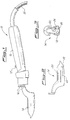
- Figure 1 represents schematically, in side view, the iron of the present invention;
- Figure 2 represents schematically a partly sectioned side view of the heating body of the iron;
- Figure 3 represents schematically a cross-section of the same heating body;
- Figure 4 represents schematically a further partly sectioned side view of the heating body, with magnified details of the internal surface of the chambers wherein the fluid is fed;
- Figure 5 represents schematically the same heating body with a magnified detail of the atomiser inserted in the heating body;
- Figure 6 represents schematically a further partly sectioned side view of the heating body;
- Figure 7 represents schematically the feeding device advantageously connected to the iron of the present invention.
-
- With reference to the above figures, the iron of the present invention, indicated as a whole by 10 in Figure 1, is basically constituted by a
body 12 having an elongated shape, with a section, by way of example circular or ovoid, forming the support and the handle of the heating body, ortool 14, connected to the front end of saidbody 12 by means known in the art, such asscrews 16.Tool 14, whose shape is of a conventional type and is shown by way of example by the figures, is obtained from metal, from instance brass, by casting, and, according to the invention, is provided in its inside with a plurality of ducts and seats variously located and developed, to cause a controlled and calibrate steam delivery through an end nozzle. In particular,tool 14 has, according to a preferred embodiment, a couple of tubular ducts communicating with one another which constitute asmany chambers cavity 22 forming the seat housing aconventional heating body 24 and ahole 26 for athermocouple 28 connected to saidbody 24. Chambers 18, 20, preferably parallel to one another, may be aligned on the same plane in the lower part oftool 14, as shown in Figure 3, or superposed, as shown in Figures 4 and 5. Theheating body 24 is advantageously constituted by an electric resistor or the like, fed through aconventional cable 30 which develops inbody 12 forming the handle ofiron 10 and comes out from the back of the same, to connect with the mains. - The longitudinal development of
chambers tool 14, in whose correspondence asmall opening 32 is formed that constitutes the steam outlet nozzle. Chambers 18, 20, communicate radially between one another though one or more connectingopenings 34; in the preferred embodiment, opening 34 is the only one, and is formed near the back front, opposite tonozzle 32, ofchambers - According to a further characteristic of the invention, the walls of said
chambers rough surface 36, as shown in detail in Figure 4; the surface roughness, which is preferably formed by a continuous threading, may be alternatively obtained by broaching interventions or the like, or directly during the casting oftool 14. - This configuration of the walls of the
chambers tool 14, is particularly effective as it substantially limits the outlet fromnozzle 32 of the non atomised fluid, contrasting its tendency to the known calefaction phenomenon. In fact, during the utilisation ofiron 10,tool 14 is heated bybody 24 to a temperature higher than 100°C, which may exceed even 200°C; the drops of fluid, generally water, that are let inevaporation chambers chambers - The increase in contact surface between fluid and metal in the inside of
chambers chambers - Said covering is formed, for instance, by a thin layer of inorganic salt, calcium chloride or the like, which is dissolved in the fluid and deposits spontaneously and homogeneously in the unevenness of the walls of
chambers tool 14; obviously, the covering may be obtained before the use oftool 14feeding chambers atomising chambers tool 14. By the protracted use ofiron 10, the accumulation of covering material along the rough surface ofchambers chambers unevennesses 40. As a consequence, also following a cleaning intervention, the interface tension between the phases of the liquid-solid system is not modified andtool 14 can be immediately re-utilised without any danger of hot liquid drops coming out fromnozzle 32. Advantageously, at the mouth ofchambers metal bush 42 is fitted in, schematised in Figure 4. Said bush has preferably an inner diameter such as to allow the stabilisation by simple mechanical interference in the mouths of said chambers, without excluding however the possibility of realising the connection by means of glues or other systems. The inner diameter ofbush 42 conditions suitably the size of the tool to be inserted inchambers - The roughness of the walls of
chamber tool 14, and the covering formed afterwards along the same walls cause the breaking of the drops of liquid, excluding the calefaction phenomenon and ensuring as a consequence that only steam comes out fromnozzle 32. The development ofchambers passage 34, determines a labyrinth-like course, sufficiently long for the fluid that, from the enteringtool 14 to the exiting throughnozzle 32, has time enough to pass into an atomised state. - To iron 10 of the present invention, there is advantageously but not critically connected a feed system suitable to mix with air the fluid prior to its entering
chambers tubular body 46, wherein twoseparate ducts mixing chamber 52.Body 46 extends, before saidchamber 52, into atube 54 having a smaller diameter, whosefront end 56 is fitted in and restrained, with known means, in the mouth of one ofchambers tool 14. With reference to the aforesaid Figure 5, thefront end 56 oftube 54 is fitted inchamber 18 which develops abovechamber 20 intool 12.Ducts filter 64 and apressure reducer 62, which is regulated as concerns both pressure and capacity. The circuit develops into twodistinct branches electrovalve 70, toduct 48 of theatomising device 44. Thesecond branch 68 of the circuit enter a water-containingtank 72, exits from the same and connects, with the interposition of anelectrovalve 74, toduct 50 of saidatomising device 44. A pressure control means, such as for instance a pressure-gauge 76, allows the control of air pressure in the circuit, which is preferably comprised between 0.005 and 0.5 bar. - Once the feeding system is activated, for instance through button 12' protruding from the handle-
body 12 ofiron 10, the system is caused to operated thanks to the simultaneous opening ofelectrovalves branches chamber 52 of theatomising device 44, wherein it mixes. The pressured air-water mix passes then intotube 54 and, through itsfront end 56, intochamber 18 oftool 14. The hole oftube 14 and therelated front end 56 is suitably calibrated to realise the atomisation of the air-water mix. At the end of the cycle or when button 12' is released, electrovalve 74 of the water-delivering branch closes, while electrovalve 70 of the air-delivering branch remains advantageously open for a fraction of second, so as to eliminate water residues fromdevice 44. This prevent the undesired generation of steam that would spontaneously form if the operator should not re-activate, within a short time, the feeding system; in fact,tube 54 of theatomising device 44 is inserted at least partly inchamber 18 oftool 14, and would heat by conduction, said tool being brought to a high temperature, generally higher than 200°C. - Through the
feeding system 60, inchambers tool 14, there does not enter water in the form of drops, but an atomised air-water mix; in this way, the formation of steam intool 14 and its exiting fromnozzle 32 are accelerated. Besides, throughsystem 60, it is possible to perfectly calibrate the quantity of water to be atomised, which quantity preferably does not exceed 3 ml/min, and which can be in any case exactly regulated. - As can be inferred from the above, the advantages of the invention are obvious.
- The iron of the present invention allows the substantially immediate delivery from
nozzle 32 oftool 14 of steam to be locally distributed on the artefact to be ironed; no danger exists of delivering hot water drops, given the presence intool 14 of labyrinth-like chambers heated tool 14. The connection ofiron 10 tomains 60, through the atomisingdevice 44, allows to exactly dose minimum water quantities and to accelerate the atomisation in the inside oftool 14. - The invention, as described hereabove and claimed hereafter, has been proposed, however, by way of mere example, being understood that the same may be susceptible of many modifications and variants, all of which fall anyhow within the inventive concept.
- For instance,
tool 14 may have a different number ofevaporation chambers 18, 19, not necessarily having a rectilinear development, to form a more or less extended labyrinth, and the roughness of the internal walls of said chambers may be discontinuous and/or differentiated, to form more or lessdeep unevennesses 40. Besides, thefluid feeding iron 10 may be obtained by any means, even though the connection to asystem 60 of the above described type is preferred. - Lastly, also possible structural inversions or alternative locations of the components or the parts that form as a whole the iron of the present invention are also possible.
Claims (17)
- An iron (10), especially suitable to be used in footwear and leatherware sectors, comprising a tool (14), tied to a grip and handling body (12), made from metal and provided internally with a plurality of ducts and seats forming one or more chambers (18, 20), for a fluid to be atomised and an adjoining cavity for a heating body (24), at least one of said chambers having a partly or entirely irregular internal surface (36), communicating with the outside of the tool (14) though a nozzle (32).
- The iron according to the preceding claim, wherein the evaporation chambers (18, 20) of tool (14) define a labyrinth-like course for the fluid fed to the same, heated at a temperature of more than 100°C from body (24) and flowing outside through said nozzle (32) of tool (14), the latter being provided with a cavity (26) for a thermocouple connected to said body (24).
- The iron according to the preceding claims, wherein at least two evaporation chambers (18, 20), communicating with one another through an opening (34), develop in the tool (14) parallel to one another, at least one of them having a partly or entirely rough inner surface:
- The iron according to the preceding claims, wherein the irregular surface (36) of at least one of said chambers (18, 20) is obtained by continuous or discontinuous threading, broaching or equivalent mechanical workings.
- The iron according to the preceding claims, wherein the irregular surface (36) of at least one of said chambers (18, 20) is obtained on casting the tool (14).
- The iron according to the preceding claims, wherein at least one of said chambers (18, 20) develops in tool (14) almost up to the end of its advanced part, on whose lower front nozzle (32) communicating with the outside is formed.
- The iron according to the preceding claims, wherein the irregular surface (36) of said chambers (18, 20) is covered by a layer (38) from material.
- The iron according to the preceding claims, wherein said material covering surface (36) is constituted by an inorganic salt.
- The iron according to the preceding claims, wherein the mouth of chambers (18, 20) of tool (14) is provided with a metal bush (42) whose inner diameter is equal to or smaller than the span of minimum diameter of said chambers.
- The iron according to one or more of the preceding claims, wherein the fluid let in chambers (18, 20) of tool (14) is constituted by water or an air-water mix coming from a feeding system (60).
- The iron according to one or more of the preceding claims; wherein the feeding system (60) develops into two separate branches (66, 60) which feed respectively, in at least one of chambers (18, 20), a pressurised air-water mix.
- The iron according to one or more of the preceding claims, wherein at least to one of chambers (18, 20) an atomising device is connected (44), connected in itr turn to said feeding system (60), comprising two separate ducts (48, 50) and a mixing chamber (52) for the pressurised air and water.
- The iron according to one or more of the preceding claims, wherein branch (68) of system (60) fits in and exits from a water-containing tank (72).
- The iron according to one or more of the preceding claims, wherein electrovalves (70, 74), regulated by a timer, are respectively interposed between branches (66, 68) of the feeding system (60).
- The iron according to one or more of the preceding claims, wherein the feeding system (60) comprises a pressure reducer (62), a filter (64) for the compressed air and a pressure-gauge (76).
- The iron according to one or more of the preceding claims, wherein said atomising device (44) extends before the mixing chamber (52) into an integral tube (50) with an end (56) connected to one of chambers (18, 20) of tool (14).
- The iron according to one or more of the preceding claims, wherein the heating body (22) of tool (14) and/or electrovalves (70, 74) of system (60) are connected to the mains through at least a cable (30) which develops in the handle-body (12) of said iron and are activated by a button (12') protruding from said body (12).
Applications Claiming Priority (2)
| Application Number | Priority Date | Filing Date | Title |
|---|---|---|---|
| IT97MI001886 IT1294305B1 (en) | 1997-08-05 | 1997-08-05 | IRON |
| ITMI971886 | 1997-08-05 |
Publications (2)
| Publication Number | Publication Date |
|---|---|
| EP0895730A2 true EP0895730A2 (en) | 1999-02-10 |
| EP0895730A3 EP0895730A3 (en) | 2000-11-22 |
Family
ID=11377728
Family Applications (1)
| Application Number | Title | Priority Date | Filing Date |
|---|---|---|---|
| EP98108168A Withdrawn EP0895730A3 (en) | 1997-08-05 | 1998-05-05 | Iron |
Country Status (6)
| Country | Link |
|---|---|
| EP (1) | EP0895730A3 (en) |
| CN (1) | CN1130999C (en) |
| BR (1) | BR9803002A (en) |
| IT (1) | IT1294305B1 (en) |
| TR (1) | TR199801077A3 (en) |
| TW (1) | TW392019B (en) |
Cited By (3)
| Publication number | Priority date | Publication date | Assignee | Title |
|---|---|---|---|---|
| WO2007110722A2 (en) | 2006-03-28 | 2007-10-04 | Elettrotecnica B.C. S.P.A. | Apparatus for ironing shoes |
| ITMI20081878A1 (en) * | 2008-10-23 | 2010-04-24 | Cottino Francesco | DEVICE FOR DISTRIBUTING A HUMIDIFIED GASEOUS FLOW |
| WO2018141838A1 (en) * | 2017-02-06 | 2018-08-09 | Arcelik Anonim Sirketi | An iron comprising a water boiling tub |
Families Citing this family (1)
| Publication number | Priority date | Publication date | Assignee | Title |
|---|---|---|---|---|
| CN112030502B (en) * | 2020-08-17 | 2021-05-14 | 江西旺来科技有限公司 | More energy-conserving and even clothing presses that irones |
Citations (9)
| Publication number | Priority date | Publication date | Assignee | Title |
|---|---|---|---|---|
| US2234547A (en) * | 1939-04-12 | 1941-03-11 | United Shoe Machinery Corp | Method of and apparatus for smoothing shoe uppers |
| US2683320A (en) * | 1948-11-05 | 1954-07-13 | Westinghouse Electric Corp | Steam iron |
| US2967365A (en) * | 1954-07-15 | 1961-01-10 | Gen Electric | Boiler coating and method for applying |
| US3170257A (en) * | 1962-09-17 | 1965-02-23 | Dziadulonis Walter | Portable iron |
| US3694942A (en) * | 1967-10-24 | 1972-10-03 | Westinghouse Electric Corp | Steam chamber coatings |
| DE3006783A1 (en) * | 1980-02-22 | 1981-08-27 | Ritter Aluminium Gmbh, 7300 Esslingen | Stainless steel mesh insert for smoothing iron steam chamber - gives improved steam production and can use undistilled water |
| JPH02268800A (en) * | 1989-04-10 | 1990-11-02 | Matsushita Electric Ind Co Ltd | Steam iron |
| US5390432A (en) * | 1992-09-29 | 1995-02-21 | Seb S.A. | Water distribution screen on a coated steam iron vaporization chamber |
| US5592764A (en) * | 1993-07-16 | 1997-01-14 | Seb S.A. | Evaporation chamber with anti-calefaction layer |
-
1997
- 1997-08-05 IT IT97MI001886 patent/IT1294305B1/en active IP Right Grant
-
1998
- 1998-04-28 TW TW87106527A patent/TW392019B/en not_active IP Right Cessation
- 1998-05-05 EP EP98108168A patent/EP0895730A3/en not_active Withdrawn
- 1998-06-12 TR TR1998/01077A patent/TR199801077A3/en unknown
- 1998-07-24 BR BR9803002A patent/BR9803002A/en not_active IP Right Cessation
- 1998-08-05 CN CN 98103489 patent/CN1130999C/en not_active Expired - Fee Related
Patent Citations (9)
| Publication number | Priority date | Publication date | Assignee | Title |
|---|---|---|---|---|
| US2234547A (en) * | 1939-04-12 | 1941-03-11 | United Shoe Machinery Corp | Method of and apparatus for smoothing shoe uppers |
| US2683320A (en) * | 1948-11-05 | 1954-07-13 | Westinghouse Electric Corp | Steam iron |
| US2967365A (en) * | 1954-07-15 | 1961-01-10 | Gen Electric | Boiler coating and method for applying |
| US3170257A (en) * | 1962-09-17 | 1965-02-23 | Dziadulonis Walter | Portable iron |
| US3694942A (en) * | 1967-10-24 | 1972-10-03 | Westinghouse Electric Corp | Steam chamber coatings |
| DE3006783A1 (en) * | 1980-02-22 | 1981-08-27 | Ritter Aluminium Gmbh, 7300 Esslingen | Stainless steel mesh insert for smoothing iron steam chamber - gives improved steam production and can use undistilled water |
| JPH02268800A (en) * | 1989-04-10 | 1990-11-02 | Matsushita Electric Ind Co Ltd | Steam iron |
| US5390432A (en) * | 1992-09-29 | 1995-02-21 | Seb S.A. | Water distribution screen on a coated steam iron vaporization chamber |
| US5592764A (en) * | 1993-07-16 | 1997-01-14 | Seb S.A. | Evaporation chamber with anti-calefaction layer |
Non-Patent Citations (1)
| Title |
|---|
| PATENT ABSTRACTS OF JAPAN vol. 015, no. 031 (C-0798), 24 January 1991 (1991-01-24) -& JP 02 268800 A (MATSUSHITA ELECTRIC IND CO LTD), 2 November 1990 (1990-11-02) * |
Cited By (6)
| Publication number | Priority date | Publication date | Assignee | Title |
|---|---|---|---|---|
| WO2007110722A2 (en) | 2006-03-28 | 2007-10-04 | Elettrotecnica B.C. S.P.A. | Apparatus for ironing shoes |
| WO2007110722A3 (en) * | 2006-03-28 | 2007-12-06 | Elettrotecnica B C S P A | Apparatus for ironing shoes |
| ITMI20081878A1 (en) * | 2008-10-23 | 2010-04-24 | Cottino Francesco | DEVICE FOR DISTRIBUTING A HUMIDIFIED GASEOUS FLOW |
| WO2010046743A3 (en) * | 2008-10-23 | 2010-06-17 | Cottino, Francesco | A device for delivering an humidified gas flow |
| CN102202538A (en) * | 2008-10-23 | 2011-09-28 | 弗朗切斯·科蒂诺 | A device for delivering an humidified gas flow |
| WO2018141838A1 (en) * | 2017-02-06 | 2018-08-09 | Arcelik Anonim Sirketi | An iron comprising a water boiling tub |
Also Published As
| Publication number | Publication date |
|---|---|
| TR199801077A2 (en) | 1999-02-22 |
| TW392019B (en) | 2000-06-01 |
| IT1294305B1 (en) | 1999-03-24 |
| CN1130999C (en) | 2003-12-17 |
| EP0895730A3 (en) | 2000-11-22 |
| BR9803002A (en) | 1999-11-03 |
| TR199801077A3 (en) | 1999-02-22 |
| CN1207418A (en) | 1999-02-10 |
| ITMI971886A1 (en) | 1999-02-05 |
Similar Documents
| Publication | Publication Date | Title |
|---|---|---|
| US6289551B1 (en) | Steam cleaning apparatus | |
| JP7267356B2 (en) | Systems for steam cleaning | |
| US3599357A (en) | Electric pressing iron | |
| US7191554B2 (en) | Steam iron | |
| EP1441059A1 (en) | Process for treating fabrics in a domestic laundry dryer | |
| US7065907B2 (en) | Electric steaming device | |
| AU3513901A (en) | Steam mop | |
| EP0895730A2 (en) | Iron | |
| US2807503A (en) | Garment spotting apparatus | |
| DE10332656A1 (en) | Process for treating textiles in a household clothes dryer | |
| EP3846949A1 (en) | Hot water-cleaning device and method for operating a hot water-cleaning device | |
| US6678973B2 (en) | Vapor distribution device, particularly for electrical household appliances | |
| CN114729496B (en) | fabric steam ironing machine | |
| ITMI970805A1 (en) | STEAM IRONING STATION | |
| KR20130087223A (en) | Hair washing apparatus | |
| JP2009273560A (en) | Steam iron | |
| US1099264A (en) | Flat-iron. | |
| KR20160104415A (en) | A steam device for beauty | |
| KR950000953Y1 (en) | Steam generator | |
| US1649337A (en) | Mangle | |
| US1246190A (en) | Bath-tub. | |
| GB2117012A (en) | Steam iron | |
| JPH0375198B2 (en) | ||
| DE357567T1 (en) | DEVICE FOR ACTIVATING PERBORATE IN WASHING MACHINES. | |
| DE1952416U (en) | HOUSEHOLD IRONING MACHINE. |
Legal Events
| Date | Code | Title | Description |
|---|---|---|---|
| PUAI | Public reference made under article 153(3) epc to a published international application that has entered the european phase |
Free format text: ORIGINAL CODE: 0009012 |
|
| AK | Designated contracting states |
Kind code of ref document: A2 Designated state(s): DE ES FR GB GR IT PT |
|
| AX | Request for extension of the european patent |
Free format text: AL;LT;LV;MK;RO;SI |
|
| PUAL | Search report despatched |
Free format text: ORIGINAL CODE: 0009013 |
|
| AK | Designated contracting states |
Kind code of ref document: A3 Designated state(s): AT BE CH CY DE DK ES FI FR GB GR IE IT LI LU MC NL PT SE |
|
| AX | Request for extension of the european patent |
Free format text: AL;LT;LV;MK;RO;SI |
|
| RIC1 | Information provided on ipc code assigned before grant |
Free format text: 7A 43D 95/02 A, 7D 06F 75/12 B |
|
| 17P | Request for examination filed |
Effective date: 20010419 |
|
| AKX | Designation fees paid |
Free format text: DE ES FR GB GR IT PT |
|
| 17Q | First examination report despatched |
Effective date: 20020603 |
|
| STAA | Information on the status of an ep patent application or granted ep patent |
Free format text: STATUS: THE APPLICATION IS DEEMED TO BE WITHDRAWN |
|
| 18D | Application deemed to be withdrawn |
Effective date: 20021015 |